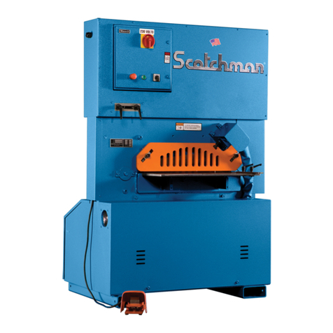
Scotchman Porta-Fab 45 User manual

MADE IN THE USA
You have downloaded a manual for our
Model Porta-Fab 45 Ironworker. This
manual does not include all of the
optional tooling for this machine. If you
would like a tooling manual, please
download the #20 Tooling Manual.

www.scotchman.com
MODEL
PORTA-FAB
45 TON
IRONWORKER
SCOTCHMAN INDS. - 180 E US HWY 14 - PO BOX 850 - PHILIP, SD 57567 Call: 1-800-843-8844
JANUARY 2022

Page 2
Open End Brake
7.12 50
TABLE OF CONTENTS
SECTION
1.0
2.0
3.0
4.0
4.1
DESCRIPTION
INTRODUCTION
SAFETY PRECAUTIONS
2.1 Warranty
WARNING LABELS
INSTALLATION & SET UP
Physical Dimensions
4.2 Machine Moving Procedures
Physical Inspection
4.3
4.4 Electrical Requirements
4.5 Machine Start-up
5.0
5.1
5.2
6.0
6.1
6.2
7.0
7.1
7.2
7.3
7.4
7.5
7.6
7.7
7.8
7.9
MAINTENANCE
Lubrication
Scheduled Maintenance
MACHINE OPERATION
Punch Operation
Three in One Shear
OPTIONAL TOOLING
Rod Shear
Six Inch Brake
Eight & Twelve Inch Brakes
Pipe Notcher
Rectangle Notcher
Picket Tool
6 x 6 Ninety Degree Notcher
Square Tube Shear
Optional Die Holders & Strippers
7.10 Multi-Shear Tool
7.11 Weld Coupon Bender Tool
PAGE #
3
4-5
5
6-7
8-11
8
10
10
12
12
13-15
13
14
16-25
16
22
26-49
27
28
30
34
38
40
42
44
44
46
48

TABLE OF CONTENTS
SECTION
8.0
8.1
8.2
8.3
9.0
9.1
9.2
9.3
9.4
9.5
9.6
9.7
10.0
11.0
DESCRIPTION
TROUBLE SHOOTING GUIDE
Electrical - Motor
Hydraulic
Cylinder Seal Replacement
MACHINE PARTS LISTS
Punch Assembly
Optional Stand Assembly
Base Assembly
Power Unit
3 in 1 Combination Tool
Optional 30" Stop Assembly
Stroke Control
WIRING DIAGRAM
HYDRAULIC SCHEMATIC
The SCOTCHMAN IRONWORKER is a versatile, multi-purpose, shearing, punching and forming
machine engineered for trouble free operation. The design of the machine combines simplicity of
operation with smooth, full stroke control.
The ability of the operator to control the machine’s direction of movement at any point in the stroke,
(i.e. stop, jog or reverse) gives the SCOTCHMAN IRONWORKER a tremendous advantage over
mechanical ironworkers.
There is no chance of the SCOTCHMAN IRONWORKER being accidentally tripped.
The hydraulic system operates at a maximum pressure of 2,500 PSI (172 BAR) and is protected from
overload by a built-in relief valve.
PAGE #
51-53
51
51
52
54-67
54
56
58
60
62
64
66
68
75
Page 3
1.0 INTRODUCTION

Page 4
2.0 SAFETY PRECAUTIONS
1. The operators of this machine must be qualified and well trained in the operation of the machine.
The operators must be aware of the capacities of the machine and the proper use of the hold-down
devices, strippers and guards provided with the machine.
2. All of the guards, adjustable restrictors and awareness barriers must be installed on the machine
and kept in good working order. Promptly replace worn or damaged parts with authorized parts.
3. Never place any part of your body into or under any of the machine’s moving parts, strippers or
hold devices.
4. Wear the appropriate personal protective equipment. Safety glasses are required at all times,
whether operating, setting up or observing this machine in operation. Since heavy pieces of metal
with sharp edges can be processed on this machine, the operators should also wear steel-toed shoes
and tight fitting leather gloves.
5. Strictly comply with all warning labels and decals on the machine. Never remove any of the labels
and replace worn or damaged labels promptly.
6. Always disconnect and lock out the power when performing maintenance work or setting up any
tooling on the machine. Follow the procedures outlined in the operator’s manual for setting up,
changing or aligning any tooling on this machine.
7. Never operate this machine with dull or damaged tooling. Replace worn punches, dies and blades
promptly.
8. Practice good housekeeping. Keep the area around the machine clean and well lit. Do not obstruct
the operator’s position by placing anything around the machine that impedes the operator’s
access to the machine.
9. Never modify this machine in any way without the written permission of the manufacturer.
10. Never leave this machine running unattended.
11. Set up a program of routine inspections and maintenance for this machine. Make all repairs and
adjustments in accordance with the manufacturer’s instructions.
12. A safety dvd was mailed to you or shipped with this machine. If you did not receive it, please
contact the factory or your local dealer immediately and one will be sent to you at no charge.
If the machine was purchased used, please contact the factory for a safety tape.

Page 5
2.1 WARRANTY
SCOTCHMAN INDUSTRIES, INC. will, within three years of the date of purchase, replace F.O.B. the
factory or refund the purchase price for any goods which are defective in materials or workmanship,
provided the buyer returns the warranty registration card within thirty (30) days of the purchase date
and, at the seller’s option, returns the defective goods freight and delivery prepaid to the seller, which
shall be the seller’s sole and exclusive remedy for defective goods.
Hydraulic and electric components are subject to their respective manufacturer’s warranties.
This warranty does not apply to machines and/or components which have been altered, changed or
modified in any way or subjected to abuse and abnormal use, inadequate maintenance and lubrication or
subjected to use beyond the seller’s recommended capacities and specifications.
In no event shall the seller be liable for labor cost expended on such goods or consequential damages.
The seller shall not be liable to purchaser or any other person for loss or damage directly or indirectly
arising from the use of the goods or from any other cause.
No officer, employee or agent of the seller is authorized to make any oral representations or warranty of
fitness or to waive any of the foregoing terms of sale and none shall be binding on the seller.
Any electrical changes made to the standard machine due to local electrical code variation must be paid
by purchaser.
As we constantly strive to improve our products, we reserve the right to make changes without
notification.

Page 6
SECTION 3.0 WARNING LABELS
DESCRIPTION
PART #
QTY
ITEM
PUNCH & DIE WARNING
003110
1
20K PUNCH STICKER003190
1
15" SCOTCHMAN DECAL
010115
1
PORTA-FAB CAPACITY DECAL
012372
1
U.S. DATA PLATE
019100
1
DECAL "LUBRICATE"
019103
1
DECAL "GREASE POINT"
019105
5
RIGHT HAND RULE 12"
019300
1
A
B
C
US FLAG DECAL
019127
1
E
D
F
G
H
ILARGE SAFETY GLASSES
003100
1
J
K110V STICKER
093001
1
45 DECAL PACKAGE
003565
L
M
1
1
FINGERS BEYOND BAR GUARD
003105
ANGLE SHEAR FRONT DECAL
016328
N1CAUTION CONTAMINATION (not shown)
003175
O1DECAL"RESERVOIR CAPACITY" (not shown)
019102
K1 230V 1PH STICKER
019120
1
P
3.0 WARNING LABELS

Page 7
FIGURE 1

Page 8
4.0 INSTALLATION AND SET-UP
CAUTION: THIS SECTION DISCUSSES INSTALLATION AND SET-UP PROCEDURES.
PLEASE READ ALL SECTIONS OF THIS MANUAL THOROUGHLY BEFORE OPERATING
THIS MACHINE.
4.1 PHYSICAL DIMENSIONS
A Floor To The Top Of Die Holder 22.04 55.98 39.54 100.43
INCHES CM INCHES CM
93.22
WITHOUT STAND WITH STAND
141.30
288 KG635 LBS.275 KG605 LBS.
B Floor To Punch Bolster 19.20 48.77 36.70
C
D
E
F
G
H
I
Throat Depth 4.25 10.80
Floor To Tool Table 21.45 54.48 38.95 98.93
Punch Stroke 1.06 2.70 1.06 2.70
Height 38.13 96.85 55.63
Length 38.12 96.82
Width 20 50.80
4.25 10.80
38.12 96.82
20 50.80
Weight

Page 9
A
22.04
A
39.54
B
19.20
B
36.70
C
4.25
D
21.45
D
38.95
F
38.13
F
55.63
G
38.12
H
20.00
H
20.00
012351
Tool
012351
Tool
080061
012351
Tool
080061
012351
Tool
WITHOUT STAND
WITH STAND
FIGURE 2

Page 10
4.2 MACHINE MOVING PROCEDURES
CAUTION: BE SURE THAT ANY LIFTING DEVICE HAS ADEQUATE CAPACITY
BEFORE ATTEMPTING TO MOVE THIS MACHINE.
The weight of this machine is 605 pounds (274.42 kg) without the optional stand and 635 pounds
(288.03 kg) with the stand. FIGURE 3 ON THE FOLLOWING PAGE DEMONSTRATES THE USE OF
AN OVERHEAD LIFT OR A FORK LIFT. These are the only two recommended methods of moving
this machine. The machine should be moved by the use of an overhead lift if it is not equipped with the
optional stand and with a forklift if it is equipped with the stand. When using a fork lift, spread the forks
of the lift as wide as possible, for stability. Lift only on the base of the machine. Do not lift the machine by
placing the forks under the base of the optional stand.
4.3 PHYSICAL INSPECTION
Any damage to the machine during shipment should be reported to the delivery carrier immediately
and a damage report made out so that a claim can be placed. The carrier is responsible for shipping
damage, but it is the customer’s responsibility to report damages, external or internal, immediately.
After the machine has been positioned, the shroud on the operator’s side should be removed and an
inspection made of the interior for missing or damaged parts.

Page 11
FIGURE 3
WARNING
SAFETY GLASSES REQUIRED WHEN
OPERATING OR OBSERVING THIS MACHINE
NEVER-
NEVER-
NEVER-
NEVER-
NEVER-
NEVER-
NEVER-
TO PREVENT SERIOUS BODILY INJURY
Operate, install tooling, service or adjust machine without
operator's manual and safety film.
Service machine with electrical power connected.
Operate any station without the respective strippers or
Operate machine with protective guards removed.
Place any part of your body under blade, punch or moving
Operate punch station without checking the punch to die
alignment and tightness.
Punch half holes, punch or shear unknown materials, side load
DO NOT REMOVE THIS SIGN FROM THIS MACHINE
REV. 0310
FOR MORE INFORMATION CONTACT SCOTCHMAN INDUSTRIES INC.
1-800-843-8844
003100
proper instructions and without reading and understanding the
hold-downs in place.
members.
(Check alignment and tightness daily.)
press brakes.
AT
080061
LIFTING FORKS HERE
TOWARDS OUTSIDE
WITH OPTIONAL STAND
WITHOUT OPTIONAL STAND
012351
Tool
080061
012351
Tool

Page 12
4.4 ELECTRICAL REQUIREMENTS
A 10 foot (3 meter) cord is provided with this machine. The plug you install on the cord must have a
minimum rating of 30 amps. We do not recommend using extension cords with this machine. If there is
a case where an extension cord must be used, it must be of adequate gauge and rating to support the
amp draw of this motor. Failure to adequately size an extension cord for this machine may result in
damage to the machine. Any extension cord used with this machine must be at least 10 gauge and have
ends rated for 30 amps. Check the motor data tag for full load current requirements.
4.5 MACHINE START-UP
Before starting this machine, take time to thoroughly review the safety dvd and the operator’s
manual. We strongly urge you to follow the OSHA directive CFR-1910.147 (effective 09-01-90)
regarding lock-out, tag-out procedures.
Before powering the machine, be sure that all packing materials and tools have been removed from the
machine and that all work stations are clear.
CAUTION: TO PREVENT DAMAGE TO THE MOTOR AND DANGER TO THE
OPERATOR, ALL ELECTRICAL CONNECTIONS SHOULD BE MADE BY A
LICENSED ELECTRICIAN.
MOTOR VOLTAGE
1PH 220/230V
RPM: 1425/1725
POWER RATING: 2HP
FULL LOAD CURRENT
FRAME: 56C
HZ: 60/50
1PH 110/115V 22.5/19 AMPS
11.5/9.5 Amps

Page 13
5.0 MAINTENANCE
The Scotchman Ironworker is an exceptionally rugged machine designed for long life with a minimum
amount of maintenance. A regular program of servicing will extend the machine's life and prevent costly
downtime.
5.1 LUBRICATION
IMPORTANT: Before operating the Porta-Fab Ironworker, apply oil to the THREE IN ONE
TOOL blades and the punch and die. Re-oil the punches and dies every 5 to 10 holes and the
blades every 10 to 15 cuts. The oil will allow the machine to shear, punch and strip easier and
increase tool life considerably. We recommend cutting oil or motor oil swabbed on with a small
brush or applied with a squirt can or spray applicator. Grease the main pivot pin and the punch
barrel and guide daily.
A multi-purpose, Molybdenum Disulfide (Dow Corning BR-2 or equivalent), high pressure, bearing
grease is recommended. Check the oil level in the reservoir once a month. To check the oil level, remove
the filler cap and measure the depth of the oil in the reservoir. The fluid should be 1/2 of an inch below
the top of the reservoir. Use a lightweight, non-foaming, hydraulic oil such as Mobil DTE 16, Shell Pellus
46, Texaco Rando 46 or equivalent.

Page 14
5.2 SCHEDULED MAINTENANCE
A program of scheduled maintenance should be set up and documented according to your application
and the frequency you use this machine. The following is a list of important items that should be included
in a scheduled maintenance program:
1. EVERY 250 HOURS OR THREE MONTHS:
A. Check the clearance between the punch barrel (A) and the punch barrel guide (B).
FOR PARTS IDENTIFICATION, SEE FIGURE 4 ON THE FOLLOWING PAGE.
TO CHECK THE CLEARANCE:
1. With a punch and die properly installed following the instructions in SECTION 6.1, operate the
machine until the punch enters the die.
2. With the punch in the die, jog the machine with the foot pedal, watching for lateral movement of
the punch in the die.
3. If lateral movement is noted, turn the machine’s power off. Remove the punch barrel (A) and
punch barrel guide (B) from the machine and check the tolerance between the two parts.
4. If the tolerance exceeds three (.003) thousandths of an inch (.07mm), replace both parts.
5. When replacing these parts, do not over tighten the drag link bolts (C & E). The bolts should be
tight enough to restrict the punch barrel from rotating, but not so tight that they won’t allow the
drag links (D) to rotate as the arm travels down.
2. EVERY 500 HOURS OR SIX MONTHS:
A. Check the condition of the blades and any component tools for wear. Replace worn parts
promptly.

Page 15
FIGURE 4

Page 16
6.0 MACHINE OPERATION
6.1 PUNCH OPERATION
ALWAYS WEAR SAFETY GLASSES.
THE FIRST AND MOST IMPORTANT PROCEDURE IS THE PROPER METHOD OF
INSTALLING AND ALIGNING PUNCHES AND DIES.
WARNING: FAILURE TO PROPERLY ALIGN PUNCHES AND DIES CAN CAUSE
SERIOUS INJURY TO PERSONNEL AND/OR DAMAGE TO EQUIPMENT. PLEASE READ
CAREFULLY AND UNDERSTAND THE FOLLOWING METHOD. IT WILL ALSO BE
HELPFUL TO REFER TO THE SAFETY DVD PROVIDED FOR A VISUAL REFERENCE.
IF YOU DID NOT RECEIVE A SAFETY DVD, PLEASE CONTACT YOUR DEALER OR
THE FACTORY.
FIGURE 5

Page 17
A. ALIGNMENT AND REMOVAL OF PUNCHES AND DIES.
REFER TO FIGURE 5 ON THE PRECEDING PAGE.
1. With the punch in the down position and the arm up, turn the machine’s electrical power OFF.
2. Remove the stripper (B) by pressing down on the tab (A) and pulling the stripper toward you.
3. Loosen and remove the bolts (G) holding the die holder (C) and remove the die holder (C) and
spacer (D).
4. Loosen the set screw holding the die. Remove the die and set it aside.
5. Loosen and remove the punch retaining nut (E) and set the punch retaining nut and punch aside.
6 . Select the proper punch and die. Make sure that there is proper clearance between the punch and
die. FOR RECOMMENDED CLEARANCES, SEE PARAGRAPH F IN SECTION 6.1.
PLEASE NOTE: ALL OF OUR #20K PUNCHES, INCLUDING OVALS, SQUARES,
HEXAGONS AND SPECIAL ORDER PUNCHES, ARE SUPPLIED WITH AN ALIGNMENT
KEY-WAY MACHINED INTO THE PUNCH. THIS KEY-WAY MATES WITH A KEY BUILT
INTO THE MACHINE’S PUNCH BARREL. ALL PUNCHES USED ON THIS MACHINE
MUST BE THE #20K STYLE.
7. Clean both the punch and the die.
8. Insert the proper punch in the punch retaining nut (E) and thread it into the punch barrel (F) and
tighten it with a wrench. If you are using a shaped punch, rotate the punch by hand until it seats
on the key, before tightening the nut.
9. Insert the proper die in the die holder with the flat side of the die aligned with the set screw.
Tighten the set screw firmly with a hex key wrench.
10. Place the die holder on the bolster and raise it up so that the punch enters the die.
11. Insert the spacer plate (D) between the die holder (C) and the bolster.

Page 18
12. Align the punch to the die so that there is equal clearance on all sides of the punch in the die.
13. Insert and tighten both the die holder bolts (G) firmly.
14. Check to be sure that the punch and die are still in alignment. Realign, if necessary.
15. Replace the stripper (B).
NOTE: If punching holes larger than 1", remove the stripper plate or, it will be damaged.
16. Check to make sure that there are no objects (such as tools) on or under any of the moving parts
of the machine.
17. Turn the machine on.
18. Lubricate the punch and die before using and every 5 to 10 holes, thereafter.
FOR LUBRICATION INSTRUCTIONS, SEE SECTION 5.1.
¼
CAUTION: REMOVE THE PUNCH AND DIE WHEN IT IS NOT IN USE.
B. CHECK PUNCHING TOOLS FOR TIGHTNESS.
Periodically during the day, check the punch and die for alignment. To do this, run the punch
down until it enters the die and turn the machine’s power OFF. Tighten the set screw holding the
die, the die holder bolts and the punch retaining nut. Check the alignment of the punch and die.
Power the machine and jog the punch up and down several times, to be sure of proper alignment.
C. CONTACT BOTH SIDES OF THE STRIPPER.
Punch holes with sufficient material to contact both sides of the punch stripper. If the workpiece
does not contact both sides of the stripper, the side thrust may break the punch and will deform
the workpiece.
D. SPECIAL STRIPPERS MAY BE REQUIRED FOR CERTAIN JOBS.
The standard stripper has been designed to work for most applications. For other applications,
such as stripping small channel, a special stripper may have to be fabricated. The important
consideration is to keep material level while stripping. When punching thin strap iron, the
material will tend to draw up into the stripper. To prevent this, a plate or large washer can be
attached to the bottom of the stripper, to reduce the size of the opening. This type of stripper will
also allow you to punch in the corners of material. There is an oversize stripper available for
oversize punching applications.
E. PUNCHING ANGLE IRON.
This machine is designed to punch angle iron with the leg down. If the application requires
punching closer to the web than the standard dies allow, special offset dies are available.

E. PUNCHING ANGLE IRON.
This machine is designed to punch angle iron with the leg down. If the application requires punching
closer to the web than the standard dies allow, special offset dies are available.
FOR ADDITIONAL INFORMATION ON PUNCHES AND DIES, SEE THE TOOLING MANUAL.
CAUTION: PUNCHING ANGLE IRON WITH THE LEG UP WILL CAUSE DAMAGE TO THE
PUNCH RETAINING NUT.
F. PUNCHING CAPACITIES.
MAXIMUM PUNCH SIZES FOR MILD STEEL (65,000 PSI TENSILE)
MATERIAL THICKNESS DIAMETER OF HOLE
INCHES MM INCHES MM
1/4 6 OPTIONAL DIE HOLDER 2-1/4 57
5/16 7.9 OPTIONAL DIE HOLDER 1-3/4 44
3/8 8 STANDARD DIE HOLDER 1-1/4 32
1/2 12 STANDARD DIE HOLDER 1-1/8 28
► NOTE: 1/2 INCH IS THE MAXIMUM MATERIAL THICKNESS.
SEE FIGURE 6 ON THE NEXT PAGE FOR CHART SHOWING TONNAGE REQUIREMENTS
Page 19
Table of contents
Other Scotchman Lathe manuals

