22
ENGLISH
Original instructions
CONTENTS
1. Introduction..........................................22
2. Technical specification.........................22
3. Contents of packing .............................22
4. Features ................................................22
5 Safety instructions................................23
5.1 Specific safety instructions ..................23
5.2 Electrical safety....................................23
6 Assembly..............................................23
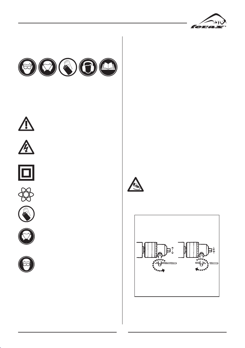
6.1 (Re)placing a drill ...............................23
6.2 Mounting the side handle.....................24
7 Use .......................................................24
7.1 Drills.....................................................24
7.2 The On/Off switch.................................24
7.3 Switch-lock ..........................................24
7.4 Adjusting of the maximum rotation
speed.....................................................24
7.5 Switching the direction of rotation ......24
7.6 Switch for percussion drilling..............25
7.7 User tips ...............................................25
8 Service & maintenance ........................25
8.1 Maintenance.........................................25
8.2 Cleaning ...............................................25
8.3 Lubrication...........................................25
8.4 Faults....................................................25
8.5 Environment.........................................25
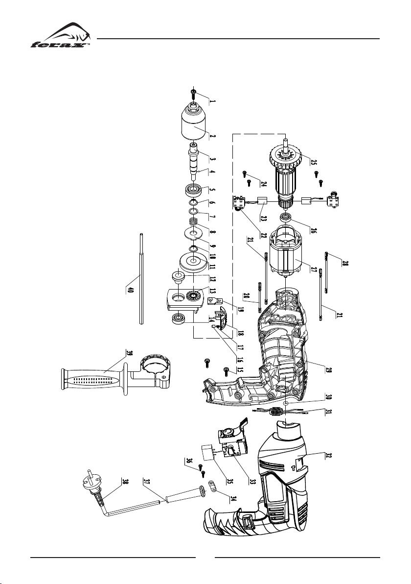
Spare parts list...............................................40
EC conformity declaration............................41
1. INTRODUCTION
Always read the instruction for elec-
trical products carefully before use. It
will help you understand your product
more easily and avoid unnecessary risks. Keep
this instruction manual in a safe place for
future use.
The machine is intended for impact drilling in
materials as brick and concrete. Besides it can
be used for drilling holes in wood, metal and
plastics.
2.
TECHNICAL SPECIFICATION
Voltage ....................................... V 230
Frequency................................. Hz 50
Input power............................... W 710
No load speed ...................... r/min 0-2300
Weight....................................... kg 2.2
Lpa (sound pressure)...........dB(A) 95.5+3
Lwa (sound power).............dB(A) 106.5+3
Vibration value
Impact drill into concrete....... m/s217.74
................................................ m/s2K=1.5
Drill into metal....................... m/s23.42
................................................ m/s2K=1.5
3.CONTENTS OF PACKING
1 Impact drill
1 Depth limiter
1 Chuck key
1 Auxiliary handle
1 Safety instructions
1 Instruction manual
1 Warranty card
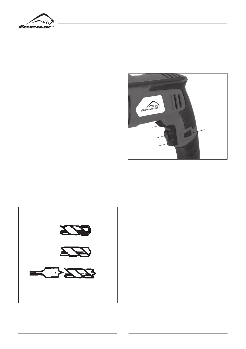
4. FEATURES
1
3
2
4
7
5
8
6
Fig. 1
1. Drill dept limiter
2. Chuck
3. Switch for normal and percussion drilling
4. Side handle
5. Left/right switch
6. On/off switch with speed control