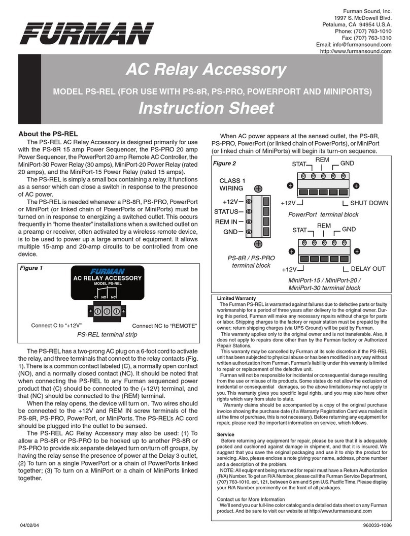
Fermax WAY KIT User guide

1
RELÉ WAY
WAY RELAY
RELAIS WAY
WAY RELAYS
RELÉ WAY
MANUAL DE INSTALADOR
INSTALLER’S MANUAL
MANUEL D’INSTALLATION
INSTALLATIONSHANDBUCH
MANUAL DO INSTALADOR

2
DIP
123
123
ON
lock Control
Jumper
1
2
3
GND
NO
COM
NC 12V
S2
S1
GND
POWER
IN-USE
BUS
DIP
GND NO COM NC
DT-RLC 2-WIRE SYSTEM
12V S2 S1 GND
POWER IN-USE BUS BUS RISER
1
2
3
El relé way es un dispositivo diseñado para la activación del abrepuertas en sistemas
DT. Tiene las siguientes características:
•Permite abrir puertas a través de abrepuertas.
•Compatible con abrepuertas de alto consumo de potencia.
•Con posibilidad de ajustar el tiempo de activación del abrepuertas.
•Con contacto para botón de salida.
1. Acerca del RELÉ WAY
Descripción:
+12V: 12V salida alimentación. Puede usarse para alimentar el abrepuertas.
S2: Reservado.
S1: Contacto de botón de salida. Conexión del botón de salida entre los contactos S1
y GND.
GND: Contacto de tierra común a los otros 3 contactos: S1, S2 y +12V.
NC: Contacto normalmente cerrado para COM.
COM: Contacto común del relé de abrepuertas.
NO: contacto normalmente abierto para COM.
Puente control abrepuertas (jumper): Para seleccionar el tipo de abrepuertas:
Vease apartados 5, 6 y 7.
POWER: Indicador de funcionamiento, se encenderá cuando se conecte la
alimentación.
IN-USE: Indicador de abrepuertas, se encenderá cuando se conecte el abrepuertas.
Bus: Conexión de la línea de bus, sin polaridad.
DIP: Utilizado para ajustar la dirección del relé.
Cod. 97840b V12_18
POWER
IN-USE
Puente
(jumper)
control
abrepuertas
2. Elementos y conexiones
12V S2 S1 GNDGND NO COM NC
BUS BUS
REF 1418
MODULO RELE WAY
WAY RELAY MODULE
POWER IN-USE
RISER
RoHS
Compliant

3
3. Montaje
Montaje carril DIN
4. Cómo ajustar el tiempo de activación del abrepuertas
NOTA: Ver esquemas (6-7) al final de este manual.
1). Dar alimentación y durante los 5 primeros segundos, cortocircuitar S2 y GND
durante 3 segundos, el indicador IN-USE parpadea.
2). Cortocircuitar S1 y GND durante 3 segundos. El indicador IN-USE se encenderá de
manera constante.
3). Volver a cortocircuitar S2 y GND. El tiempo que se mantenga este corticircuito es
equivalente al tiempo activación del abrepuertas. (El indicador IN-USE parpadea
una vez por segundo. El tiempo de ajuste máximo es de 30 segundos).
4). Una vez quitado el cortocircuito entre S2 y GND, el tiempo de abrepuertas queda
almacenado.
El interruptor DIP en la parte trasera se utiliza para ajustar la dirección del relé. Por
favor, véase la información a continuación para obtener más detalles sobre los ajustes
DIP:
Ajustes del DIP para el abrepuertas
GND NO COM NC
DT-RLC 2-WIRE SYSTEM
12V S2 S1 GND
POWER IN-USE BUS BUS RISER
1
2
3
5. Ajuste de interruptor DIP
12V S2 S1 GNDGND NO COM NC
BUS BUS
REF 1418
MODULO RELE WAY
WAY RELAY MODULE
POWER IN-USE
RISER
RoHS
Compliant
-2-
DIP Estado Bit Descripción
OFF,OFF,OFF Para abrepuertas 1 de la puerta 1.
OFF,OFF,ON
Relé para el control del segundo abrepuertas de la
puerta 1:
- Sin alimentador adicional (Esquema 6).
- Con alimentador adicional (Esquema 7):
• A) Con Abrepuertas eléctrico
• B) Con Abrepuertas magnético
123
ON
123
ON

4
DIP
123
123
ON
lock Control
Jumper
1
2
3
GND
NO
COM
NC 12V
S2
S1
GND
POWER
IN-USE
BUS
DIP
GND NO COM NC
DT-RLC 2-WIRE SYSTEM
12V S2 S1 GND
POWER IN-USE BUS BUS RISER
1
2
3
The way relay is a unlock function device designed for DT system to control door locks.
It has the features as follows:
•Allows to open gate door locks;
•Support high power-consumption lock;
•With configurable unlock timed output;
•Support exit control button.
1. About WAY RELAY Unit
Description:
+12V: 12V power output. Can be used to power the lock.
S2: Reserved.
S1: Exit button contact. Short this contact and the GND to unlock.
GND:The common Ground of the other 3 contacts: S1, S2 and +12V.
NC:The normally-closed contact to COM.
COM: The common contact of the unlock relay.
NO: The normally-open contact to COM.
Lock Control Jumper: To select the lock type: see section 5, 6 and 7.
POWER: Working indicator, it will light up when plugs in power supply.
IN-USE: Unlock indicator,it will light up when unlock.
Bus:Connect to the bus line, no polarity.
DIP: Used for setting the address of the relay.
POWER
IN-USE
Lock
Control
Jumper
2. Parts and Name
12V S2 S1 GNDGND NO COM NC
BUS BUS
REF 1418
MODULO RELE WAY
WAY RELAY MODULE
POWER IN-USE
RISER
RoHS
Compliant

5
NOTE: See diagrams (6-7) at the end of this manual.
1). Power-on within 5 seconds, short-circuit S2 up to 3 seconds, the IN-USE indicator
flash.
2). Short-circuit S1 up to 3 seconds, and the IN-USE indicator always light.
3). Short-circuit again S2, at this time,the short-circuit time equal to unlock delay time.
(the IN-USE indicator flashes once per second, Less than two seconds by one
second calculation; The maximum setting time is 30 seconds.)
4). After S2 released, saved unlock delay, and exit the setting.
GND NO COM NC
DT-RLC 2-WIRE SYSTEM
12V S2 S1 GND
POWER IN-USE BUS BUS RISER
1
2
3
DIN Rail Mounting
The DIP switch in the back of the panel is used to set the address of the relay. Please
refer to the followings for more detail informations about the DIP settings:
DIP settings for lock.
3. Unit Mounting
4. How to set the unlock delay time
5. DIP Switch Setting
12V S2 S1 GNDGND NO COM NC
BUS BUS
REF 1418
MODULO RELE WAY
WAY RELAY MODULE
POWER IN-USE
RISER
RoHS
Compliant
-2-
DIP Bit State Descriptions
OFF,OFF,OFF Lock 1 of the panel 1.
OFF,OFF,ON
Relay for control the second lock of the panel 1:
- Without external power supply (Wiring diagram 6).
- With external power supply (Wiring diagram 7):
• A) With Electric lock type
• B) With Magnetic lock type
123
ON
123
ON

6
DIP
123
123
ON
lock Control
Jumper
1
2
3
GND
NO
COM
NC 12V
S2
S1
GND
POWER
IN-USE
BUS
DIP
GND NO COM NC
DT-RLC 2-WIRE SYSTEM
12V S2 S1 GND
POWER IN-USE BUS BUS RISER
1
2
3
L’actionneur du relais way est un dispositif de déverrouillage conçu pour les systèmes
DT en vue de contrôler les différentes gâches. Il présente les caractéristiques sui-
vantes :
•Permet d’ouvrir les gâches de la porte d’entrée.
•Compatible avec une gâche à forte consommation électrique.
•Avec sortie temporisée de la gâche configurable.
•Compatible avec le bouton de sortie.
1. À propos du RELAIS WAY
Description:
+12V: Sortie d’une puissance de 12 V. Peut servir à alimenter la gâche.
S2: Réservé.
S1: Contact du bouton de sortie. Connexion du bouton de sortie entre les contacts S1
et GND.
GND: Contact de masse commun aux 3 autres contacts: S1, S2 et + 12V.
NC: Contact normalement fermé sur COM.
COM: Contact commun du relais de déverrouillage.
NO: Contact normalement ouvert sur COM.
Cavalier de commande du verrouillage: Pour sélectionner le type de verrouillage :
voir point 5, 6 y 7.
POWER: Témoin de fonctionnement, il s’allumera en cas d’alimentation.
IN-USE: Témoin de déverrouillage, il s’allumera en cas de déverrouillage.
Bus: Connexion à la ligne de bus, pas de polarité.
DIP: Utilisé pour la configuration de l’adresse du relais.
POWER
IN-USE
Cavalier de
commande du
verrouillage
2. Éléments et leur désignaƟon
12V S2 S1 GNDGND NO COM NC
BUS BUS
REF 1418
MODULO RELE WAY
WAY RELAY MODULE
POWER IN-USE
RISER
RoHS
Compliant

7
4. Comment régler le délai de temporisaon de déverrouillage
REMARQUE : voir schémas (6-7) à la fin de ce manuel.
1). Alimentation sous 5 secondes, court-circuit de S2 jusqu’à 3 secondes, le témoin IN-
USE clignote.
2). Court-circuit de S1 jusqu’à 3 secondes ; le témoin IN-USE est allumé en perma-
nence.
3). Nouveau court-circuit de S2, à ce moment, le temps du court-circuit est identique
au délai de temporisation de déverrouillage (le témoin IN-USE clignote une fois
toutes les secondes, moins de deux secondes pour un calcul de 1 seconde, le
réglage du temps maximal est de 30 secondes).
4). Une fois S2 relâché et le délai de déverrouillage enregistré, quittez le réglage.
Le DIP switch se trouve à l’arrière du module sert à configurer l’adresse du relais.
Réglages DIP de la gâche.
3. Installaon de l’unité
GND NO COM NC
DT-RLC 2-WIRE SYSTEM
12V S2 S1 GND
POWER IN-USE BUS BUS RISER
1
2
3
Installation du rail DIN
5. Configuraon de l’adresse du relais
12V S2 S1 GNDGND NO COM NC
BUS BUS
REF 1418
MODULO RELE WAY
WAY RELAY MODULE
POWER IN-USE
RISER
RoHS
Compliant
-2-
DIP État binaire Descriptions
OFF,OFF,OFF S'applique à la gâche 1 de la platine 1.
OFF,OFF,ON
Relais : commande de la deuxième gâche de la
platine 1:
- Sans alimentation externe (Schéma 6).
- Avec alimentation externe (Schéma 7):
• A) Avec Gachê èlectronique
• B) Avec Gachê électro-magnétique
123
ON
123
ON

8
DIP
123
123
ON
lock Control
Jumper
1
2
3
GND
NO
COM
NC 12V
S2
S1
GND
POWER
IN-USE
BUS
DIP
GND NO COM NC
DT-RLC 2-WIRE SYSTEM
12V S2 S1 GND
POWER IN-USE BUS BUS RISER
1
2
3
Das Relais WAY dient in DT-Systemen dazu, die Türöffner zu steuern. Es verfügt über
folgende Funktionen:
•Ermöglicht das Entriegeln von Türöffnern;
•Unterstützt die Verwendung eines Türschlosses mit hohem Stromverbrauch;
•Mit konfigurierbarem Ausgang (Verzögerungszeit);
•Unterstützt Türöffnungstaste
1. Über das Relais WAY
Beschreibung:
+12V: 12-V-Stromausgang. Kann verwendet werden, um den Türöffner mit Strom zu
versorgen.
S2: Reserviert.
S1: Kontakt Türöffnungstaste. Türöffnungstaste zwischen S1 und GND anschließen.
GND: Gemeinsame Erdung der anderen 3 Kontakte: S1, S2 und +12 V.
NC: Kontakt für COM normalerweise geschlossen.
COM: Der gemeinsame Kontakt des Türöffner-Relais.
NO: Kontakt für COM normalerweise offen.
Steckbrücke zur Steuerung des Türöffners: Zur Auswahl des Türöffnertyps: Siehe
Abschnitte 5, 6 und 7.
POWER: EIN-/AUS-Anzeige, leuchtet auf, wenn das Netzgerät angeschlossen wird.
IN-USE: In Betrieb: Türöffneranzeige, leuchtet auf, wenn der Türöffner angeschlossen
wird.
Bus: Anschluss an die Bus-Leitung, ohne Polarität.
DIP: Einstellung der Relais-Adresse.
EIN/AUS
IN BETRIEB
Steckbrücke
Steuerung der
Türöffnungstaste
2. Elemente und Anschlüsse
12V S2 S1 GNDGND NO COM NC
BUS BUS
REF 1418
MODULO RELE WAY
WAY RELAY MODULE
POWER IN-USE
RISER
RoHS
Compliant

9
3. Montage
4. Einstellung der bei Auslösung des Türöffners
HINWEIS: Siehe Schemata (6 - 7) am Ende dieses Handbuchs.
1). Unter Strom setzen und innerhalb von 5 Sekunden S2 und GND 3 Sekunden lang
kurzschließen, die IN-BETRIEB-Anzeige blinkt.
2). S1 und GND 3 Sekunden lang kurzschließen, die IN-BETRIEB-Anzeige leuchtet
permanent.
3). S2 und GND erneut kurzschließen. Die Dauer der Kurzschlusszeit ist dabei gleich
der Verzögerungszeit. (Die IN-BETRIEB-Anzeige blinkt im Sekundentakt. Die maxi-
male Verzögerungszeit beträgt 30 Sekunden.)
4). Durch Aufheben des Kurzschlusses zwischen S2 und GND wird die Türöffnungszeit
automatisch gespeichert.
Der DIP-Schalter auf der Rückseite des Bedienfelds wird dazu verwendet, die Adresse
des RLC einzustellen. Bitte nachfolgende Information beachten, um weitere Informati-
on über die DIP-Einstellungen zu erhalten.
DIP-Einstellungen für den Türöffner.
GND NO COM NC
DT-RLC 2-WIRE SYSTEM
12V S2 S1 GND
POWER IN-USE BUS BUS RISER
1
2
3
WAY RELAY
DIN-Schienenmontage
5. Einstellung der DIP-Schalter
12V S2 S1 GNDGND NO COM NC
BUS BUS
REF 1418
MODULO RELE WAY
WAY RELAY MODULE
POWER IN-USE
RISER
RoHS
Compliant
-2-
DIP Bit-Status Beschreibungen
OFF,OFF,OFF Gilt für Türöffner 1 von Türstation 1.
OFF,OFF,ON
Relais zur Steuerung des zweiten Türöffners de
r
Türstation 1:
- Ohne externes Netzgerät (Schemata 6).
- Mit externes Netzgerät (Schemata 7):
• A) Mit Elektronischer Türöffner
• B) Mit Elektromagnetischer Türöffner
123
ON
123
ON

10
DIP
123
123
ON
lock Control
Jumper
1
2
3
GND
NO
COM
NC 12V
S2
S1
GND
POWER
IN-USE
BUS
DIP
GND NO COM NC
DT-RLC 2-WIRE SYSTEM
12V S2 S1 GND
POWER IN-USE BUS BUS RISER
1
2
3
O atuador de relé way é um dispositivo com função de desbloqueio destinado ao con-
trolo de trincos pelo sistema DT. Apresenta as seguintes características:
•Permite a abertura de trincos de porta;
•Suporta trincos de alto consumo energético;
•Com saída de desbloqueio temporizada configurável;
•Suporta o botão de controlo de saídas.
1. Acerca do RELÉ WAY
Descrição:
+12V: 1Saída de 12 V de potência. Pode ser usada para alimentar o trinco.
S2: Reservado.
S1: Contacto do botão de saída. Curto-circuitar este contacto e GND para desbloque-
ar.
GND: Terra comum dos outros 3 contactos: S1, S2 e +12V.
NC: Contacto normalmente fechado para COM.
COM: Contacto comum do relé de desbloqueio
NO: Contacto normalmente aberto para COM.
Jumper de controlo do bloqueio: Para selecionar o tipo de bloqueio: consulte a sec-
ção 5, 6 e 7.
POWER: Indicador de funcionamento que se ilumina quando recebe alimentação de
energia.
IN-USE: Indicador de desbloqueio que se ilumina ao desbloquear.
Bus: Ligação à linha de barramento, sem polaridade.
DIP: Usa-se para definir o endereço do relé.
POWER
IN-USE
Jumper de
controlo do
bloqueio
WAY RELAY
2. Peças e designações
12V S2 S1 GNDGND NO COM NC
BUS BUS
REF 1418
MODULO RELE WAY
WAY RELAY MODULE
POWER IN-USE
RISER
RoHS
Compliant

11
3. Montagem do aparelho
4. Como definir a temporização do desbloqueio
NOTA: Ver esquemas (6-7) no final deste manual.
1). Dentro de 5 segundos após ligar, curto-circuitar S2 até 3 segundos; o indicador
EM USO pisca.
2). Curto-circuitar S1 até 3 segundos; o indicador EM USO ilumina-se permanente-
mente.
3). Curto-circuitar S2 de novo; neste momento, o tempo de curto-circuito é igual à
temporização de desbloqueio (o indicador EM USO ilumina-se uma vez por se-
gundo, menos de dois segundos por cálculo de um segundo; o tempo máximo de
ajuste é de 30 segundos).
4). Depois de soltar S2, guarde a temporização de desbloqueio e abandone o ajuste.
Usa-se o DIP switch na parte posterior do painel para definir o endereço do RLC. Por
favor, consulte o seguinte para informações mais detalhadas sobre as definições DIP:
Definições DIP para bloqueio.
GND NO COM NC
DT-RLC 2-WIRE SYSTEM
12V S2 S1 GND
POWER IN-USE BUS BUS RISER
1
2
3
WAY RELAY
Montagem em calha DIN
5. Definição do DIP switch
12V S2 S1 GNDGND NO COM NC
BUS BUS
REF 1418
MODULO RELE WAY
WAY RELAY MODULE
POWER IN-USE
RISER
RoHS
Compliant
-2-
DIP Estado do Bit Descrições
OFF,OFF,OFF Aplica-se ao trinco 1 de là porta 1.
OFF,OFF,ON
Relé controla o segundo trinco de là porta 1:
- Sem fonte de alimentação externa (Esquema 6).
- Com fonte de alimentação externa (Esquema 7):
• A) Com Trinco eletrónico
• B) Com Trinco eletromagnético
123
ON
123
ON

12
6. Internal powered lock connection (only suitable for
electronic lock 12Vdc máx. 450mA).
Relay for control the second lock of door station 1.
BUS(IM) BUS(DS)
PC6
Exit Button
GNDS1S212V
NCCOMNOGND
E-lock
AC~
monitor
-
+
L1 L2 PL S+ S-
1# Camera
(Device Address:0)
NO
POWER IN-USE BUS
GND COM NC
DT-RLC
2-WIRE SYSTEM
12V S2 S1 GND
BUS RISER
1
2
3
-
+
123
ON
DIP
6. Conexión de abrepuertas sin alimentador adicional (sólo
apto para abrepuertas de 12Vdc máx. 450mA).
Relé para el control del segundo abrepuertas de la puerta 1.
PSU
ref. 1410
Abrepuertas
Lock
Gachê
Türöffner
Trinco
CON puente
WITH jumper
AVEC jumper
MIT Steckbrücke
EM jumper
1
2
3
CON puente
WITH jumper
AVEC jumper
MIT Steckbrücke
EM jumper
6. Raccordement de la gâche alimentée en interne (gachê
èlectronique12Vdc max. 450mA).
Relais : commande de la deuxième gâche de la plane de rue 1.
6. Schloss mit interner Stromversorgung (elektronisches
Schloss 12 VDC, max. 450 mA).
Relais zur Steuerung des zweiten Türöffners der Türstaon 1.
6. Ligação de bloqueio alimentada internamente (trinco
eletrónico 12Vdc máx. 450mA).
Relé controla o segundo bloqueio da estação de porta 1.
Botón de salida
Exit Button
Bouton-poussoir hall d’entrée
Türöffnungstaste
Botão do hall de entrada.
12V S2 S1 GNDGND NO COM NC
BUS BUS
REF 1418
MODULO RELE WAY
WAY RELAY MODULE
POWER IN-USE
RISER
RoHS
Compliant

13
7. External Power Supply powered lock connection
BUS(IM) BUS(DS)
PC6
Exit Button
GNDS1S212V
NCCOMNOGND
AC~
monitor
-
+
L1 L2 PL S+ S-
adaptor for the lock
E-lock
1# Camera
(Device Address:0)
-
+
NO
POWER IN-USE BUS
GND COM NC
DT-RLC
2-WIRE SYSTEM
12V S2 S1 GND
BUS RISER
1
2
3
A. Electronic lock type:
123
ON
DIP
Relay control the second lock of door station 1.
PSU
ref. 1410
SIN puente
WITHOUT jumper
SANS jumper
OHNE Steckbrücke
SEM jumper
1
2
3
SIN puente
WITHOUT jumper
SANS jumper
OHNE Steckbrücke
SEM jumper
7. Conexión de abrepuertas con alimentador adicional
A. Abrepuertas eléctrico
Relé para el control del segundo abrepuertas de la puerta 1.
7.
L’alimentaon externe alimente le raccordement de la gâche
A. Gachê èlectronique
Relais : commande de la deuxième gâche de la plane de rue 1.
7. Ein externes Netzgerät speist den Türöffner
A. Elektronischer Türöffner
Relais zur Steuerung des zweiten Türöffners der Türstaon 1.
7. Ligação de trinco alimentada por fonte de alimentação ex-
terna
A. Trinco eletrónico
Relé controla o segundo bloqueio da estação de porta 1.
Abrepuertas
Lock
Gachê
Türöffner
Trinco
Botón de salida
Exit Button
Bouton-poussoir hall d’entrée
Türöffnungstaste
Botão do hall de entrada.
12V S2 S1 GNDGND NO COM NC
BUS BUS
REF 1418
MODULO RELE WAY
WAY RELAY MODULE
POWER IN-USE
RISER
RoHS
Compliant

14
BUS(IM) BUS(DS)
PC6
Exit Button
GNDS1S212V
NCCOMNOGND
AC~
monitor
-
+
L1 L2 PL S+ S-
adaptor for the lock
EM-lock
1# Camera
(Device Address:0)
NO
POWER IN-USE BUS
GND COM NC
DT-RLC 2-WIRE SYSTEM
12V S2 S1 GND
BUS RISER
1
2
3
-
+
B.Magnetic lock type:
123
ON
DIP
Relay control the second lock of door station 1.
B. Abrepuertas magnético.
Relé para el control del segundo abrepuertas de la puerta 1.
1
2
3
PSU
ref. 1410
B. Gachê électro-magnéque.
Relais : commande de la deuxième gâche de la plane de rue 1.
B. Elektromagnescher Türöffner
Relais zur Steuerung des zweiten Türöffners der Tür 1.
Botón de salida
Exit Button
Bouton-poussoir hall d’entrée
Türöffnungstaste
Botão do hall de entrada.
B. Trinco eletromagnético.
Relé controla o segundo bloqueio da estação de porta 1.
Abrepuertas
Lock
Gachê
Türöffner
Trinco
SIN puente
WITHOUT jumper
SANS jumper
OHNE Steckbrücke
SEM jumper
SIN puente
WITHOUT jumper
SANS jumper
OHNE Steckbrücke
SEM jumper
12V S2 S1 GNDGND NO COM NC
BUS BUS
REF 1418
MODULO RELE WAY
WAY RELAY MODULE
POWER IN-USE
RISER
RoHS
Compliant

15
8. Specification
•Power Supply : 24 Vdc;
•Unlocking Time: 1~30s(Default 1s).
•Lock Power supply: 12Vdc, 450mA(Internal Power),
•Working Temperature: -100C~+400C.
•Dimension: 89(H)×71(W)×45(D)mm.
8. Especificaciones
•Alimentación: 24 Vdc;
•Tiempo de activación abrepuertas: 1~30s (por defecto 1s).
•Alimentación abrepuertas: 12 V CC, 450 mA (alimentación interna).
•Temperatura de trabajo: -10 0C~+40 0C.
•Dimensiones: 89 (H) × 71 (A) × 45 (P) mm.
8. Caractéristiques
•Alimentation : 24 Vcc;
•Durée de deverrouillage : 1~30 s (par défaut 1 s).
•Alimentation de la gâche : 12 Vcc, 450 mA (alimentation interne).
•Température de service : -10 0C~+40 0C.
•Dimensions : 89 (H) × 71 (L) × 45 (P) mm.
8. Technische Daten
•Stromversorgung: 24 VDC;
•Entriegelungszeit: 1 ~ 30 s (standardmäßig 1 s)
•Stromversorgung Türöffner: 12 VDC, 450 mA (Eigenspeisung)
•Betriebstemperatur: - 10º C ~ + 40º C
•Abmessungen: 89 (H) × 71 (B) × 45 (T) mm
8. Especificações:
•Alimentação: 24 Vdc;
•Tempo de desbloqueio: 1~30 s (por predefinição: 1 s);
•Alimentação de energia para bloqueio: 12 VDC, 450 mA (potência interna);
•Temperatura de serviço: -10 0C ~ +40 0C;
•Dimensões: 89 (A) x 71 (L) x 45 (P) mm.

16
Publicação técnica de carácter informativo editada pela FERMAX ELECTRONICA.
A FERMAX, na sua política de constante melhoria, reserva-se o direito de modificar
o conteúdo deste documento, assim como as características dos produtos que nele
são referidos, a qualquer momento e sem aviso prévio. Qualquer modificação será
apresentada em edições posteriores deste documento.
Publicación técnica de caracter informativo editada por FERMAX ELECTRÓNICA.
FERMAX, en su politica de mejora constante, se reserva el derecho a modificar el
contenido de este documento así como las características de los productos que en el se
refieren en cualquier momento y sin previo aviso. Cualquier modificación será reflejada en
posteriores ediciones de este documento.
Technical document published for information purposes by FERMAX ELECTRÓNICA.
FERMAX, in a policy of ongoing improvement, reserves the right to modify the contents
of this document and the feature of the products referred to herein at any time and with
no prior notice. Any such modifications shall be reflected in subsequent editions of this
document.
Publication technique à caractère informatif éditée par FERMAX ELECTRÓNICA.
Conformément à sa politique de perfectionnement continu, FERMAX se réserve le droit
de modifier, à tout moment et sans préavis, le contenu de ce document ainsi que les
caractéristiques des produits auxquels il est fait référence. Toutes les modifications
seront indiquées dans les éditions suivantes.
Technische Veröffentlichung zu Informationszwecken; Herausgeber: FERMAX ELECTRONICA.
FERMAX behält sich das Recht vor, den Inhalt dieses Dokuments sowie die technischen
Eigenschaften der erwähnten Produkte ohne vorherige Ankündigung zu ändern, um
dadurch den ständigen Weiterentwicklungen und den damit in Verbindung stehenden
Verbesserungen Rechnung zu tragen. Alle Änderungen werden in den Neuauflagen dieses
Dokuments berücksichtigt.
Avd. Tres Cruces, 133
46017 Valencia
Spain
Other manuals for WAY KIT
1
Table of contents
Languages:
Other Fermax Relay manuals
Popular Relay manuals by other brands
ABB
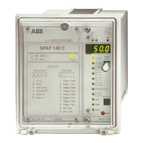
ABB SPAF 140 C User manual and technical description

ZIEHL
ZIEHL COSFI100V operating manual
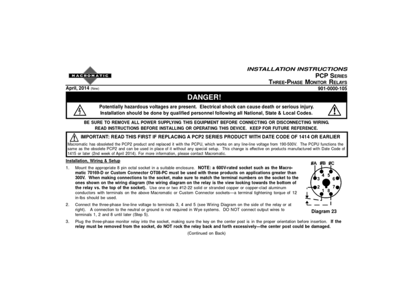
macromatic
macromatic PCP series installation instructions
Rockwell Automation
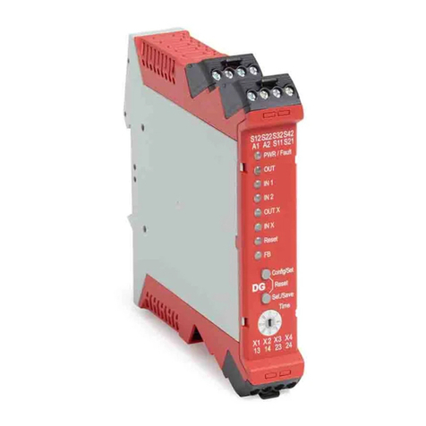
Rockwell Automation Allen-Bradley Minotaur 440R installation instructions

Identiv
Identiv PRIMIS FR-50-40-E installation guide
Omron
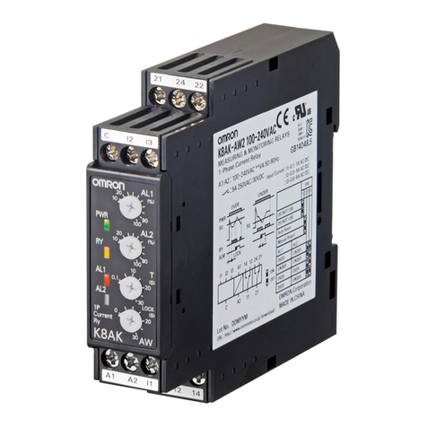
Omron K8AK-AW Series manual
