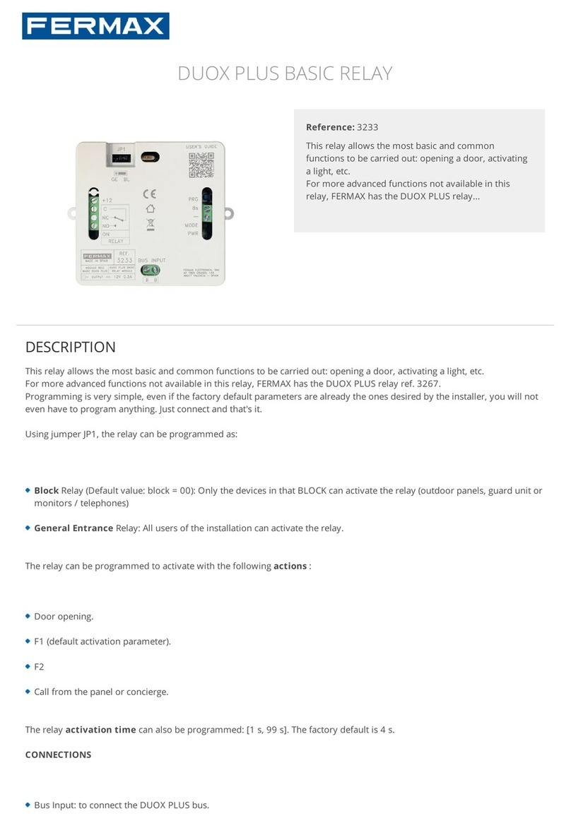
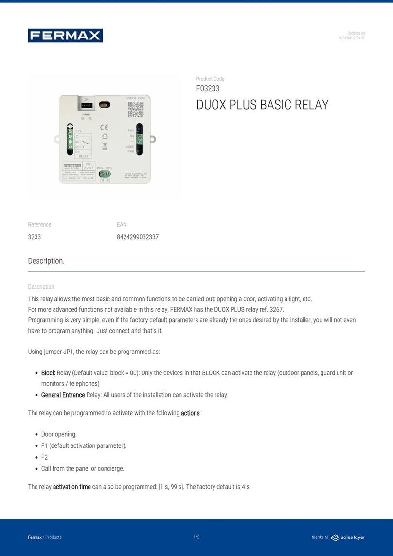
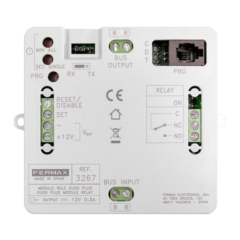
Fermax DUOX RELAY User manual

DUOX RELAY advanced manual
INSTALLATION MANUAL

Page 2
Code 97822Ib V11_19
CONGRATULATIONS ON PURCHASING THIS QUALITY PRODUCT!
Fermax electronics manufactures and develops top class equipment which fulfil the highest
design and technology standards.
We hope you enjoy its range of functions.
www.fermax.com.
DUOX RELAY advanced manual

Page 3
INDEX
1. INTRODUCTION........................................................................................................ 6
1.1 Functions/ Configurations.............................................................................. 7
1.2. Usage guidelines.......................................................................................... 8
1.3 Basic connection diagram............................................................................. 8
2. CONFIGURATIONS -FUNCTIONS............................................................................ 9
CONFIGURATIONS
2.1 Configuration as Block ................................................................................ 9
2.2 Configuration as General Entrance .............................................................. 9
2.3 Resetting Parameters.................................................................................... 9
2.4 Configuring activation times via integrated buttons.......................................10
FUNCTIONS
2.5 Functions depending on operating mode......................................................10
2.5.1 TX Operating Mode.............................................................................10
2.5.1.1 Lock-release function upon receiving a call...............................10
2.5.1.2 Lock-release function in configured panel.................................11
2.5.1.3 Call guard unit function..............................................................12
2.5.1.4 Activate or deactivate F1 relay ..................................................13
2.5.1.5 Activate or deactivate F2 relay ..................................................14
2.5.1.6 Activate or deactivate remote relay ...........................................16
2.5.1.7 Doormatic Function ..................................................................17
2.5.2 RX Operating Mode.............................................................................18
2.5.2.1 Activating relay upon receiving lock-release command.18
2.5.2.2 Activation of the relay upon receiving a call to residence com-
mand from a panel...................................................................21
2.5.2.3 Activating relay upon receiving call to guard unit command......24
2.5.2.4 Activating relay upon receiving self-start command ..................27
2.5.2.5 Activating relay upon receiving activate F1 relay command......30
2.5.2.6 Activating relay upon receiving activate F2 relay command......33
2.3.2.7 Activating or deactivating relay upon receiving an activate/deacti-
vate command ........................................................................36

Page 4
3. CONFIGURATIONS - FUNCTIONS PROGR. WITH DUOX PROGRAMMER..........38
CONFIGURATIONS
3.1. Resetting Parameters ..................................................................................38
3.2 Configurating activation times.......................................................................38
FUNCTIONS
3.3 Functions depending on operating mode......................................................39
3.3.1 TX Operating Mode.............................................................................39
3.3.1.1 Lock-release function upon receiving a call...............................39
3.3.1.2 Lock-release function in configured panel.................................40
3.3.1.3 Call guard unit function..............................................................41
3.3.1.4 Activate or deactivate F1 relay ..................................................42
3.3.1.5 Activate or deactivate F2 relay ..................................................43
3.3.1.6 Activate or deactivate remote relay ...........................................45
3.3.1.7 Doormatic Function ..................................................................47
3.3.2 RX Operating Mode.............................................................................48
3.3.2.1 Activating relay upon receiving lock-release command.............48
3.3.2.2 Activation of the relay upon receiving a call to residence com-
mand from a street panel.........................................................51
3.3.2.3 Activating relay upon receiving call to guard unit command......54
3.3.2.4 Activating relay upon receiving self-start command .................57
3.3.2.5 Activating relay upon receiving activate F1 relay command......60
3.3.2.6 Activating relay upon receiving activate F2 relay command......63
3.3.2.7 Activating or deactivating relay upon receiving an activate/deacti-
vate command ........................................................................66
4. TECHNICAL CHARACTERISTICS ...........................................................................67

Page 5
Installation manual

Page 6
1. INTRODUCTION
The DUOX Relay allows for dry contacts in BUS2 systems, with various operating and activa-
tion modes to be configured:
- Relay activation using commands generated from the residential terminals, entry panels
or guard units.
- External activation using buttons, additional external switches, etc.
The DUOX relay can be installed in any part of the duox bus. You can install one or several
relays: by apartments, block or installation.
Notes:
-Theduoxrelayalsoprovidesthenecessarycurrent(12Vdc), toactivate thepower tocontrol:
standard lock-release, bells, etc.
3257
REF.
DISABLE
OUTPUT
12V 0.3A
SEC SINGLE
MIN ALL
OUT
NO
NC
C
RELAY
AV TRES CRUCES, 133
FERMAX ELECTRONICA, SAU
4 017 VALENCIA - SPAIN
MADE IN SPAIN
BUS
OUTPUT
C
D
T
RX PRG
MODULO RELE
DUOX
DUOX RELAY
MODULE
BUS INPUT
BB
PRG TX
BB
+12V
-
RESET/
SET
V
ON
2
1
3
1. BUS INPUT: DUOX Input Connector.
2. BUS OUTPUT: DUOX Output Connector.
3. Dry contacts (max 3A):
- C: Common.
- NC: Normally Closed.
- NO: Normally Open.
Relay ON: Active relay output indicator Led
4. External relay control:
- RESET/DISABLE , - : Disables any action taken on the relay (as a result of an external
command or activation) during a short circuit between both terminals.
- SET, -: Relay activation through external contact. Activates the relay as a result of a
short circuit between SET and - (negative) terminals, and also transmits commands.
+12V Auxiliary voltage output 12Vdc (300mA max).
6. Operating Mode:
- TX: The mode where the relay sends commands to other devices depending on the
configured command (in this mode, the relay does not activate the output).
- RX: Themode wheretherelayactivates theoutputifthe configuredcommandis received
by the bus and coincides with the other configured parameters.
6
4
7
9
10

Page 7
The functions implemented on the relay are summarised below.
Functions implemented in TX Mode:
- Lock-release function after receiving a call.
- Lock-release function to a configured panel.
- Guard-unit call function.
- F1 relay activation or deactivation function.
- F2 relay activation or deactivation function.
- Remote relay activation or deactivation function.
- Doormatic function.
Functions implemented in RX Mode:
- Activating the relay upon receiving a lock-release command.
- Activation upon receiving a guard-unit call command.
- Activation upon receiving a call to residence command from a panel.
- Activation upon receiving an Auto-start command.
- Activation upon receiving an Activate F1 relay command.
- Activation upon receiving an Activate F2 relay command.
- Activation upon receiving an Activate/Deactivate relay command.
Note:
- Whenever terminals from different blocks are required to activate the same relay, it must be
configured as General Entrance.
Other configurations:
- Configuration of activation times via integrated push-buttons.
- Resetting Parameters.
7. PRG: Programming Access button.
8. Min/All - Sec/Single: Buttons for Functions and Activation Times
- For Functions: In combination with the PRG button (programming input), they are
pressed to program the relay’s different possible functions.
- For activation times.
* Timed: This allows you to configure the activation time between 1 and 120 seconds
in the seconds range and between 1 and 120 minutes in the minute range.
* Continued: Allows the relay to be configured to keep the contact closed until
deactivation occurs by means of a short-circuit between the RESET and -.
9. C, D, T: LED diodes that give information when programming, relative to the status: off,
on, fast flash...etc.
10. Telephone Connector: For the DUOX Programmer connection.
1.1 FUNCTIONS / CONFIGURATIONS
VERY IMPORTANT NOTE:
Even though the relay is implemented on all functions detailed below, SOME functions may
not yet be applied because the devices used for this will be available in the future.

Page 8
1.2 USAGE CONSIDERATIONS
-There shouldn´tbemore thanonerelaywith thesameaddressin theinstallation(independent
of the type of address).
- To configure the terminal´s destinations, it must be in night mode.
- If entering the terminal addresses via the integrated button programming the ON Relay led
doesnot light-up,re-call toensure thattheaddresshasbeenproperlysaved. Ifthe addressis
alreadysaved inthememory,the leddoesnotlight-upandthe addresscan notbeduplicated.
- Once the range of addresses is programmed from the relay, you can change the start ad-
dress and place it before the last one. You must make sure that the start and end address
in the range are properly saved.
1.3 BASIC CONNECTION DIAGRAM
The DUOX relay can be installed in any part of the duox bus. You can install one or several
relays: by apartments, block or installation.
3257
REF.
DISABLE
OUTPUT 12V 0.3A
SEC SINGLE
MIN ALL
OUT
NO
NC
C
RELAY
AV TRES CRUCES, 133
FERMAX ELECTRONICA, SAU
4 017 VALENCIA - SPAIN
MADE IN SPAIN
BUS
OUTPUT
C
D
T
RX PRG
MODULO RELE
DUOX
DUOX RELAY
MODULE
BUS INPUT
BB
PRG TX
BB
+12V
-
RESET/
SET
V
ON
3257
REF.
DISABLE
OUTPUT 12V 0.3A
SEC SINGLE
MIN ALL
OUT
NO
NC
C
RELAY
AV TRES CRUCES, 133
FERMAX ELECTRONICA, SAU
4 017 VALENCIA - SPAIN
MADE IN SPAIN
BUS
OUTPUT
C
D
T
RX PRG
MODULO RELE
DUOX
DUOX RELAY
MODULE
BUS INPUT
BB
PRG TX
BB
+12V
-
RESET/
SET
V
ON
3257
REF.
DISABLE
OUTPUT 12V 0.3A
SEC SINGLE
MIN ALL
OUT
NO
NC
C
RELAY
AV TRES CRUCES, 133
FERMAX ELECTRONICA, SAU
4 017 VALENCIA - SPAIN
MADE IN SPAIN
BUS
OUTPUT
C
D
T
RX PRG
MODULO RELE
DUOX
DUOX RELAY
MODULE
BUS INPUT
BB
PRG TX
BB
+12V
-
RESET/
SET
V
ON
F1
F1
F1
F1
F1
F1
F1
F1
F1 F1 F1 F1
Vac
-+-+
18 - 24 Vdc
18Vdc/2A
MADE IN SPAIN
INPUT
REF. 3244
DUOX POWER
SUPPLY FILTER
OUTPUT
18Vdc/2A
Ref. 3244
18 Vdc IN PREV BUS
PWR BUS PWR BUS

Page 9
2. CONFIGURATIONS - FUNCTIONS
2.3 RESETTING PARAMETERS
Function description.
It performs a reset of the parameters to the default values:
- Configured command: None
- Relay address: 000
- Relay block: 00
- Continued mode: Deactivated
- Panels: Not configured
- Terminals: Not configured.
- Start of the Range: Not configured.
- End of the Range: Not configured.
- List of terminals: Empty.
- Activation time: 3 seconds.
Function configuration.
1. Press the PRG button 4 times so that the C, D and Tleds remain blinking rapidly.
2. Press the Min/All and Sec/Single buttons simultaneously, the LEDS remain fixed for
4 seconds so that when they are off, the relay´s configuration is reset to the default
parameters.
Note:
- If the duox relay has been previously configured, and if you are unsure about the previous
configuration, we recommend performing a parameter rest to not interfere with the prior
configurations.
CONFIGURATIONS
2.1 CONFIGURATION AS BLOCK
Connect the DUOX relay, press the "PRG" pushbutton, and the C led should light up. You
will then have 60 seconds to program its address. To program the address, make a call
from one of the terminals that is connected to the BUS OUTPUT terminal. The outdoor
panel of the block must previously have been programmed with the parameters of the
block number.
In this way, the block number will be configured in the relay. The relay can then be acti-
vated from any of the terminals that belong to this block number.
The DUOX relay can be configured as Block (2.1) or as General Input (2.2).
2.2 CONFIGURATION AS GENERAL ENTRANCE
If the relay is in RX mode and F1 or F2 command programming, it can be configured as a
general entrance block.
To do this, repeat the steps mentioned in 2.1, but make sure that a bridge has been set up
in advance between the – terminals and RESET/DISABLE.
In this way, the block will be configured as general entrance, and this relay will be able to
be activated from any monitor or guard unit, regardless of the block number.

Page 10
Note:
- You can not configure the times in both ranges (minutes and seconds). If the configuration
startswithintherange(minutesorseconds), continuewithin thesame rangeand thebuttons
pressed on the other range will not be considered.
Continued function configuration.
1. Press the PRG button 3 times. The Tled must remain lit.
2. Simultaneously press the buttons Sec/Single and Min/All, the leds should turn off.
Note:
- Once the relay has been activated it will remain active until a short circuit is done between
RESET and -.
2.5 FUNCTIONS DEPENDING ON OPERATING MODE
2.5.1 TX Operating Mode
-Themodewherethe relaysendscommandstoother devicesdependingontheconfigured
command (in this mode, the relay does not activate the output).
-To access this mode configure the bridge to TX mode.
FUNCTIONS:
- Lock-release function after receiving a call.
- Lock-release function to a configured panel.
- Guard-unit call function.
- F1 relay activation or deactivation function.
- F2 relay activation or deactivation function.
- Remote relay activation or deactivation function.
- Doormatic function.
FUNCTIONS
2.5.1.1 LOCK-RELEASE FUNCTION UPON RECEIVING A CALL
Function description.
You can associate the duox relay to a house so that upon calling a home you have 30 sec-
onds, via activation of the Set terminal (button connected between the SET terminals and -)
for the Lock-release command to be sent to the panel that last made the call. This way the
user does not have to go to the house´s terminal to press the lock-release button.
2.4 CONFIGURING ACTIVATION TIME VIA THE INTEGRATED BUTTONS (Sec/Single -
Min/All)
Function description.
Configuration of activation times.
* Timed: This allows you to configure the activation time between 1 and 120 seconds
in the seconds range and between 1 and 120 minutes in the minute range.
* Continued: Allows the relay to be configured to keep the contact closed until
deactivation occurs by means of a short-circuit between the RESET and -.
Timed Function configuration.
1. Press the PRG button 3 times. The Tled must remain lit.
2. a) If you want to configure the time in seconds press the Sec/Single button, with each
press it increases the time 1 second and the Tled flashes. If you have reached the
maximum configurable time (120 seconds), the T led flashes rapidly.
b) If you want to configure the time in minutes press the Min/All button, with each press
it increases the time 1 minute and the Tled flashes. If you have reached the maximum
configurable time (120 minutes), the Tled flashes rapidly.
3. Once the desired configured time is configured, press PRG. All leds must be off.

Page 11
Function configuration.
1. Make a call from a telephone in the installation and answer.
2. Press the PRG button, the Cled should light up.
3. Press the Min/All button, the C LED should blink quickly.
4. Press the Lock-release button on the previously used phone, the Cled should turn off.
This way, the command is configured on the relay being serviced, now you must configure
the terminal to include the function on.
5. Press the PRG button twice, the Dled should light up.
6. Press the Sec/Single button, the DLED should blink quickly.
7. Make a call to the terminal you want to have the function. Upon making the call the Relay
On led turns on for about 1.5 seconds.
8. Press the PRG button, all the leds must remain off. The function has been configured so
that when a call is made to the configured phone, you have 30 seconds to press the Lock-
releasebutton (SETand-),and carryoutthelock-releasefunction overthepanelyou called.
Steps to change the terminal assigned the function.
1. Press the PRG button twice, the Dled should light up.
2. Simultaneously press the Min/All and Sec/Single, the D led should remain off.
3. Repeats point 5 and 8 from the previous process.
Notes:
- This function only works with one terminal address. If you need to configure terminals
configured as “ALL,” it will not attend to any terminal address.
- In the push-button configuration mode, if no button is pressed the relay returns to standby
and all leds turn off after 300 seconds.
2.5.1.2 LOCK-RELEASE FUNCTION IN CONFIGURED PANEL
Function description.
You can associate the duox relay to a panel so that the Set terminal (button connected be-
tween the SET terminals and -), send a lock-release command to the configured panel. This
function is useful for entrance door buttons far from the street-panel.
Function configuration.
1. Make a call to a telephone in the installation from the panel you want to associate the
relay, and answer.
2. Press the PRG button, the Cled should light up.
3. Press the sec/single button, the C LED should blink slowly.
4. Press the Lock-release button on the previously used phone, the Cled should turn off.
This way you have already configured the command attending to the relay.
Steps to change the panel assigned the function.
Carry out steps 1 to 4 of the previous process.
Note:
- In the push-button configuration mode, if no button is pressed the relay returns to standby
and all leds turn off after 300 seconds.

Page 12
2.5.1.3 CALL GUARD UNIT FUNCTION
Function description.
You can install a button for calling the guard unit, and it can be installed far from the phone.
Via the terminal Set (button connected between the SETterminals and -), a call to guard unit
is made with the configured telephone´s original address, and with the configured guard unit
as destination.
Notes:
- If you want to configure with the integrated buttons on the relay (Min/All - Sec/Single), you
need a Duox telephone configured to send calls to the guard unit in Mixed mode. If you do
nothave atelephone configuredthisway, youmust dosowiththeDuoxProgrammer,seethe
correspondingchapterin Section“3. CONFIGURATIONS -FUNCTIONS: PROGRAMMING
WITH THE DUOX PROGRAMMER”.
Configure the installation in Mixed mode so that the panels may make direct calls and the
terminals may make calls to the guard unit.
Function configuration.
1. Press the PRG button, the Cled should light up.
2. Press the Sec/Single button, the CLED should blink slowly.
3. Press on a push button telephone the lock-release button (in stand-by and without having
received a call in the last 30 seconds), the CLED should remain off. This way you have
already configured the command attending to the relay. The guard unit´s address must
always be the same as the configured telephone has.
4. Press the PRG button twice, the Dled should light up.
5. Press the Sec/Single button, the DLED should blink quickly.
6. Make a call to the terminal you want to have the function. Upon making the call the Relay
On led turns on for about 1.5 seconds.
7. Press the PRG button, all the leds must remain off. The function has been configured so
that when a button connected to the SET terminal is pressed (SET and -), a call is made
to the guard unit that has the configured telephone and the originating address is that
marked during the call.
Steps to change the terminal assigned the function.
1. Press the PRG button twice, the Dled should light up.
2. Simultaneously press the Min/All and Sec/Single, the D led should remain off.
3. Repeat points 4 and 7 from the previous process.
Note:
- In the push-button configuration mode, if no button is pressed the relay returns to standby
and all leds turn off after 300 seconds.

Page 13
2.5.1.4 ACTIVATE OR DEACTIVATE THE F1 RELAY FUNCTION
Function description.
* First operating mode:
You can activate or deactivate a second remote relay configured as F1 by activating the
Set terminal (button connected between the SET and - terminals), in the relay that we are
configuring.
For this, the second relay must be configured as described in chapter: 2.5.2 RX Operat-
ing Mode, section: 2.5.2.5 ACTIVATING RELAY UPON RECEIVING ACTIVATE F1 RELAY
COMMAND.
If the relay we are configuring activates the Reset terminal (button connected between the
RESET and - terminals), the remote relay configured as F1 is deactivated.
* Second operating mode:
Continued mode. If a relay in charge of activating the second remote relay we activate
Continued mode (see: 2.4 CONFIGURATION OF ACTIVATION TIMES VIA THE
INTEGRATED PUSH BUTTONS (Sec/Single - Min/All), upon activating the first relay´s Set
terminal, the second remote relay configured as F1 is activated, and if the Set terminal is
deactivated or the Reset terminal on the first relay is activated, the second F1 remote relay
is deactivated.
TX RX
3257
REF.
DISABLE
OUTPUT 12V 0.3A
SEC SINGLE
MIN ALL
OUT
NO
NC
C
RELAY
AV TRES CRUCES, 133
FERMAX ELECTRONICA, SAU
4 017 VALENCIA - SPAIN
MADE IN SPAIN
BUS
OUTPUT
C
D
T
RX PRG
MODULO RELE
DUOX
DUOX RELAY
MODULE
BUS INPUT
BB
PRG TX
BB
+12V
-
RESET/
SET
V
ON
3257
REF.
DISABLE
OUTPUT 12V 0.3A
SEC SINGLE
MIN ALL
OUT
NO
NC
C
RELAY
AV TRES CRUCES, 133
FERMAX ELECTRONICA, SAU
4 017 VALENCIA - SPAIN
MADE IN SPAIN
BUS
OUTPUT
C
D
T
RX PRG
MODULO RELE
DUOX
DUOX RELAY
MODULE
BUS INPUT
BB
PRG TX
BB
+12V
-
RESET/
SET
V
ON
DESTINATION
receptor relay
ORIGIN
transmitter relay
(configured as Activa-
tion or Deactivation
upon RECEIVING
an Activate F1 relay
command.
second
REMOTE relay
(the one being con-
figured as SEND of
the Activation or De-
activation command
on the F1 relay) first relay
Note:
- If you want to configure with the integrated buttons on the relay (Min/All - Sec/Single), you
need a telephone with auxiliary F1 configured to send an F1 command.
- If you do not have a telephone with auxiliary F1 function (ex. an Extra telephone),
you must do so with the Duox Programmer, see the corresponding chapter in Section
“3. CONFIGURATIONS - FUNCTIONS: PROGRAMMING WITH THE DUOX
PROGRAMMER”.

Page 14
Function configuration.
1. Press the PRG button, the Cled should light up.
2. Press the Sec/Single button, the CLED should blink slowly.
3. Press the Loft Duox Extra telephone the F1 key, the CLED must remain off. This way you
havealready configuredthe commandattending tothe relay.The F1 remoterelay activated
must have the same block address as the telephone.
By default, Continued is deactivated, so upon activating the Set terminal, the F1 remote
relay is activated and and the Reset terminal deactivates the F1 remote relay.
If you want to activate the Continued mode
1. Press the PRG button 3 times, the Tled should light up.
2. Simultaneously press the Min/All and Sec/Single, all leds should remain off.
Notes:
- The time and mode (timer/Continued), configured in the relay transmitter does not effect
the receptor relay.
- Local mode (transmitter relay - relay on):
* SET ON -> Activates relay.
* RESET ON -> Deactivates relay.
- Continued mode:
Remote Relay Activation:
* SET ON -> Activates remote relay.
* SET OFF
RESET ON
If you want to activate the Continued mode.
1. Press the PRG button 3 times, the Tled should light up.
2. Press the Sec/Single button, the TLED should blink once.
3. Press the PRG button, all the leds must remain off.
Note:
- In the push-button configuration mode, if no button is pressed the relay returns to standby
and all leds turn off after 300 seconds.
Remote Relay deactivation.
2.5.1.5 ACTIVATE OR DEACTIVATE THE F2 RELAY FUNCTION
Function description.
* First operating mode:
You can activate or deactivate a second remote relay configured as F2 by activating the
Set terminal (button connected between the SET and - terminals), in the relay that we are
configuring.
For this, the second relay must be configured as described in section: 2.5.2 RX Operating
Mode, section: 2.5.2.6 ACTIVATING OR DEACTIVATING A RELAY UPON RECEIVING AN
ACTIVATE F2 RELAY COMMAND.
If the relay we are configuring activates the Reset terminal (button connected between the
RESET and - terminals), the remote relay configured as F2 is deactivated.

Page 15
TX RX
3257
REF.
DISABLE
OUTPUT 12V 0.3A
SEC SINGLE
MIN ALL
OUT
NO
NC
C
RELAY
AV TRES CRUCES, 133
FERMAX ELECTRONICA, SAU
4 017 VALENCIA - SPAIN
MADE IN SPAIN
BUS
OUTPUT
C
D
T
RX PRG
MODULO RELE
DUOX
DUOX RELAY
MODULE
BUS INPUT
BB
PRG TX
BB
+12V
-
RESET/
SET
V
ON
3257
REF.
DISABLE
OUTPUT 12V 0.3A
SEC SINGLE
MIN ALL
OUT
NO
NC
C
RELAY
AV TRES CRUCES, 133
FERMAX ELECTRONICA, SAU
4 017 VALENCIA - SPAIN
MADE IN SPAIN
BUS
OUTPUT
C
D
T
RX PRG
MODULO RELE
DUOX
DUOX RELAY
MODULE
BUS INPUT
BB
PRG TX
BB
+12V
-
RESET/
SET
V
ON
DESTINATION
receptor relay
ORIGIN
transmitter relay
(configured as Activa-
tion or Deactivation
upon RECEIVING
an Activate F2 relay
command.
second REMOTE
relay
(the one being
configured as SEND
of the command
for Activation or
Deactivation of the
F2 relay)
first relay
Note:
- If you want to configure with the integrated buttons on the relay (Min/All - Sec/Single), you
needatelephonewithanauxiliary F2function(forexample,anExtraphone, withanF2button.
If you do not have a telephone with auxiliary F2 function (ex. an Extra telephone), you
must do so with the Duox Programmer, see the corresponding chapter in Section “3.
CONFIGURATIONS -FUNCTIONS:PROGRAMMINGWITHTHEDUOXPROGRAMMER”.
Function configuration.
1. Press the PRG button, the Cled should light up.
2. Press the Sec/Single button, the CLED should blink slowly.
3. Press on the Loft Duox Extra the F2 button, the Cled should turn off. This way you have
already configured the command attending to the relay. The F2 remote relay activated
must have the same block address as the telephone.
By default, Continued is deactivated, so upon activating the Set terminal, the F2 remote
relay is activated and and the Reset terminal deactivates the F2 remote relay.
If you want to activate the Continued mode
1. Press the PRG button 3 times, the Tled should light up.
2. Simultaneously press the Min/All and Sec/Single, all leds should remain off.
* Second operating mode:
Continued mode. If a relay in charge of activating the second remote relay, we activate
Continued mode (see: 2.4 CONFIGURATION OF ACTIVATION TIMES VIA THE
INTEGRATED PUSH BUTTONS (Sec/Single - Min/All), upon activating the first relay´s Set
terminal, the second remote relay is configured as F2 is activated, and if the Set terminal
is deactivated or the Reset terminal on the first relay is activated, the second F2 remote
relay is deactivated.
Notes:
- The time and mode (timer/Continued), configured in the relay transmitter does not effect
the receptor relay.
- Local mode (transmitter relay - relay on):
* SET ON -> Activates relay.
* RESET ON -> Deactivates relay.
- Continued mode:
Remote Relay Activation:
* SET ON -> Activates remote relay.
* SET OFF
RESET ON Remote Relay deactivation:

Page 16
2.5.1.6 ACTIVATE OR DEACTIVATE THE REMOTE RELAY FUNCTION
Function description.
* First operating mode:
You can activate or deactivate a second remote relay by activating the Set terminal (button
connected between the SET and - terminals), in the relay that we are configuring.
For this, the second relay must be configured as described in section: 2.5.2 RX Operating
Mode, section: 2.5.2.7 ACTIVATING OR DEACTIVATION OF THE RELAY UPON RECEIV-
ING AN ACTIVATE/DEACTIVATE COMMAND.
If the relay we are configuring activates the Reset terminal (button connected between the
RESET and - terminals), the remote relay is deactivated.
Bydefault, Continuedfunction isdeactivated,souponactivatingtheSet terminal,theremote
relay is activated and the Reset terminal deactivates the remote relay.
Note: The time configured in the transmitter relay does not effect the receptor relay.
* Second operating mode:
Continued mode. If a relay in charge of activating the second remote relay, we activate
Continued mode (see: 2.4 CONFIGURATION OF ACTIVATION TIMES VIA THE
INTEGRATED PUSH BUTTONS (Sec/Single - Min/All), upon activating the Set terminal of
the first relay, the second remote relay is activated, and if the Set terminal is deactivated
or the Reset terminal on the first relay is activated, the second remote relay is deactivated.
If you want to deactivate the Continued mode.
1. Press the PRG button 3 times, the Tled should light up.
2. Press the Sec/Single button, the TLED should blink once.
3. Press the PRG button, all the leds must remain off.
Note:
- In the push-button configuration mode, if no button is pressed the relay returns to standby
and all leds turn off after 300 seconds.
TX RX
3257
REF.
DISABLE
OUTPUT 12V 0.3A
SEC SINGLE
MIN ALL
OUT
NO
NC
C
RELAY
AV TRES CRUCES, 133
FERMAX ELECTRONICA, SAU
4 017 VALENCIA - SPAIN
MADE IN SPAIN
BUS
OUTPUT
C
D
T
RX PRG
MODULO RELE
DUOX
DUOX RELAY
MODULE
BUS INPUT
BB
PRG TX
BB
+12V
-
RESET/
SET
V
ON
3257
REF.
DISABLE
OUTPUT 12V 0.3A
SEC SINGLE
MIN ALL
OUT
NO
NC
C
RELAY
AV TRES CRUCES, 133
FERMAX ELECTRONICA, SAU
4 017 VALENCIA - SPAIN
MADE IN SPAIN
BUS
OUTPUT
C
D
T
RX PRG
MODULO RELE
DUOX
DUOX RELAY
MODULE
BUS INPUT
BB
PRG TX
BB
+12V
-
RESET/
SET
V
ON
DESTINATION
receptor relay
ORIGIN
transmitter relay
(configured as Activa-
tion or Deactivation
upon RECEIVING an
Activate or Deacti-
vate remote relay
command.
second
REMOTE relay
(the one being
configured as SEND
of the Activation or
Deactivation com-
mand on the remote
relay)
first relay
Notes:
- This configuration can not be made using integrated push buttons in the relay (Min/All -
Sec/Single), and must be done via the Duox Programmer, see the corresponding chapter
in Section “3. CONFIGURATIONS - FUNCTIONS: PROGRAMMING WITH THE DUOX
PROGRAMMER”.

Page 17
2.5.1.7 DOORMATIC FUNCTION
Function description.
You can add the Doormatic function to a device that does not have it, (ex. the Loft Duox Basic
Telephone). When the relay receives the Normal Call command to the configured home, after
5 seconds, it sends the Lock-release command to the last panel that made the call.
Function configuration.
1. Press the PRG button, the Cled should light up.
2. Press the Min/All button, the C LED should blink quickly.
3. Make a call to any telephone from a street panel, the led Cmust remain off. This way, the
command is configured on the relay being serviced, now you must configure the terminal
to include the Doormatic function on.
4. Press the PRG button twice, the Dled should light up.
5. Press the Sec/Single button, the DLED should blink quickly.
6. Make a call to the terminal you want to have the Doormatic function. Upon making the call
the Relay On led turns on for about 1.5 seconds.
7. Press the PRG button, all the leds must remain off. The function has been configured so
that when you make a call to the configured telephone, after 5 seconds the Lock-release
is activated.
Steps to change the terminal assigned the Doormatic function.
1. Press the PRG button twice, the Dled should light up.
2. Simultaneously press the Min/All and SEC/SINGLE, the D led should remain off.
3. Repeat points 4 and 7 from the previous process.
Notes:
- This function only works with one terminal address. If you need to configure terminals
configured as “ALL,” it will not attend to any terminal address.
- In the push-button configuration mode, if no button is pressed the relay returns to standby
and all leds turn off after 300 seconds.
Notes:
- The time and mode (timer/bi-stable), configured in the relay transmitter does not effect the
receptor relay.
- Local mode (transmitter relay - relay on):
* SET ON -> Activates relay.
* RESET ON -> Deactivates relay.
- Bi-stable mode:
Remote Relay Activation:
* SET ON -> Activates remote relay.
* SET OFF
RESET ON Remote Relay deactivation:

Page 18
2.5.2 RX Operating Mode
-The modewhere therelayactivates theoutput and theconfigured commandisreceived
and coincides with the other configured parameters.
-To access this mode configure the bridge to RX mode.
FUNCTIONS:
-Activating relay upon receiving the lock-release command
- Activation the relay upon receiving a call to residence command from a panel.
- Activation of the relay upon receiving a guard-unit call command.
- Activating of the relay upon receiving an auto-start command.
- Activation of the relay upon receiving an Activate F1 relay command.
- Activation of the relayupon receiving an Activate F2 relay command.
- Activation of the relay upon receiving an Activate/Deactivate command.
- Activation of the relay for an indefinite time.
Note:
- Whenever terminals from different blocks are required to activate the same relay, it must be
configured as General Entrance.
2.5.2.1 ACTIVATION OF THE RELAY UPON RECEIVING A LOCK-RELEASE
COMMAND
Function description
You can configure the relay to activate upon receiving a Lock-release command from resi-
dence terminals.
The residence terminals send the lock-release command to the panel upon pressing the
lock-release button. The relay, if configured this way, can be activated upon receiving the
lock-release command. The residence terminals can send the lock-release command to a
specific panel or to all panels in the installation, understanding that this command is sent
individually to each of them.
- The lock-release command, relative to the residence terminals sending them can be
configured as:
* All installed terminals (ALL).
* Terminals from a list (maximum 100 terminals).
* Terminals included within a defined range (consecutive).
- The lock-release command, relative to the panels receiving them can be configured as:
* All panels (they individually receive each command, not all in the group).
For example: In the installation the panels are P1, P2, P3, P4 and P5. The residence
terminal can open the door of Panel P1 or Panel P2 or Panel P3 or Panel P4 or Panel
P5.Upon configuringthe lock-releasecommand inAll the panels,anytimeanypanel
receives it the relay is activated.
* Only one panel.
For example: In the installation the panels are P1, P2, P3, P4 and P5. The residence
terminal can open the door of Panel P1 or Panel P2 or Panel P3 or Panel P4 or Panel
P5.Upon configuringthe lock-releasecommand ina single panel, forexample,Panel
P4, only when Panel P4 receives the command is the relay activated.

Page 19
P1
P2
P3
P4
P5
F1
F1
F1
F1
F1
3257
REF.
DISABLE
OUTPUT
12V 0.3A
SEC SINGLE
MIN ALL
OUT
NO
NC
C
RELAY
AV TRES CRUCES, 133
FERMAX ELECTRONICA, SAU
4 017 VALENCIA - SPAIN
MADE IN SPAIN
BUS
OUTPUT
C
D
T
RX PRG
MODULO RELE
DUOX
DUOX RELAY
MODULE
BUS INPUT
BB
PRG TX
BB
+12V
-
RESET/
SET
V
ON
DESTINATION ORIGIN
DUOX relay
LOCK RELEASE
command
P1
P2
P3
P4
P5
P1
P2
P3
P4
P5
F1
F1
F1
F1
F1
F1
F1
F1
F1
F1
F1
F1
F1
F1
F1
One
panel
Terminals
from a
list
The range
of terminals
All the
terminals
All the
panels
Different options
Panel configuration Different options
Terminal configuration

Page 20
Function configuration.
First step: Configure the command and panel.
1. Make a call from a telephone in the installation and answer.
2. Press the PRG button, the Cled should light up.
3. a) If you want the relay to activate with the Lock-release command for all panels press the
Min/All button and the C led should flash quickly.
b) If you want the relay to activate with the Lock-release command for the panel that made
the call, press the Sec/Singlebutton, and the Cled should flash slowly.
4. Press the Lock-release button on the previously used phone, the Cled should turn off.
Second step: Configuration of the command´s origin (residence terminals).
The lock-release command, relative to the residence terminals sending them can be con-
figured as:
a) All installed terminals (ALL).
b) Terminals from a list (maximum 100 terminals).
c) Terminals included within a defined range (consecutive).
a) Configuration: All installed terminals (ALL).
1. Press the PRG button twice, the Dled should light up.
2. Press the Min/All button. The relay leds should remain off.
b) Configuration: Terminals in a list (maximum 100 terminals).
1. Press the PRG button twice, the Dled should light up.
2. Press the Sec/Single button. The Dled should flash quickly.
3. From a street panel, make a call to the telephone address we want to assign this function.
The Relay On led should light up if the telephone address is not on the list. The telephone
has been added to the list.
If you want to add more telephones, repeat this step.
To finish, press the PRG button.
Note:
- When the list is complete (100 terminals), the Relay On led flashes quickly.
Steps to DELETE the complete list
1. Press the PRG button twice, the Dled should light up.
2. Simultaneously press the Sec/Single and Min/All buttons. All leds should be off. The list
has been deleted.
c) Configuration: Terminals included within a defined range (consecutive).
1. Press the PRG button twice, the Dled should light up.
2. Press the Sec/Single button. The Dled should flash quickly.
3. Press the Min/All button. The Dled should flash slowly.
4. From a street panel, make a call to the first address in the range. Leds Cand Dshould
blink slowly.
Other manuals for DUOX RELAY
1
Table of contents
Other Fermax Relay manuals
Popular Relay manuals by other brands

GE
GE NBVllA Series instructions
Honeywell
Honeywell Farenhyt Series Installation and maintenance instructions
TE Connectivity
TE Connectivity SRS-2NO-1NC Quick installation guide
Videx
Videx 2213 Technical manual
Schweitzer Engineering Laboratories
Schweitzer Engineering Laboratories SEL-787-2 manual

Westinghouse
Westinghouse KS Installation, operation & maintenance instructions

