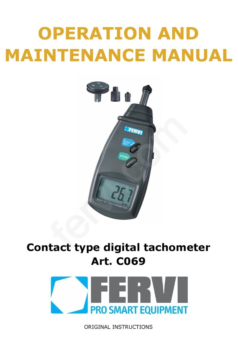
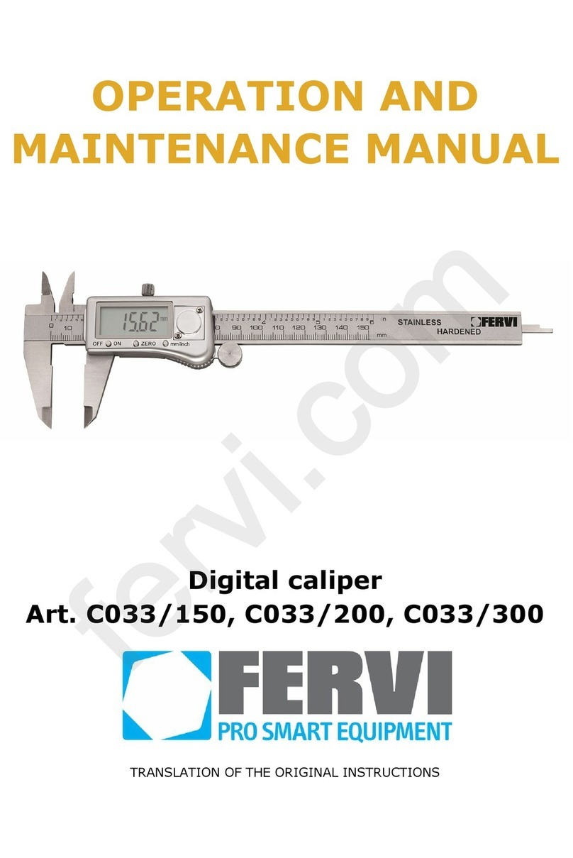
Fervi 60117 User manual

USE AND
MAINTENANCE MANUAL
Contact and optical type digital
tachometer
Art. C070
ORIGINAL INSTRUCTIONS
fervi.com

MEASURING
INSTRUMENTS
Page 2 of 6
All rights are reserved of reproduction and dissemination of this Technical Manual and documentation cited and/or attached. It is expressly forbidden to reproduce, publish or distribute any information from this Manual. Copyright by FERVI
FOREWORD
Read this manual before any operation
ORIGINAL INSTRUCTIONS
Before starting any operation it is compulsory to read this instruction manual. The guarantee
of smooth operation and full performance of the instrument is highly dependent on the
application of all the instructions contained in this manual.
Operator Qualification
The workers responsible for using this device must have all the necessary information,
education and receive adequate training regarding safety, including:
a) The conditions of use of the equipment;
b) Foreseeable abnormal situations, pursuant to Article 73 of Legislative Decree
81/08.
We guarantee the instrument complies with the specifications and technical
instructions described in the Manual on the date of its issuance (shown in this page).
On the other hand, the instrument may also be subject to important technical changes
in the future, without the manual being updated.
Therefore, see FERVI for information about modifications that could be implemented.
REV. 2
July 2014
fervi.com

MEASURING
INSTRUMENTS
Page 3 of 6
All rights are reserved of reproduction and dissemination of this Technical Manual and documentation cited and/or attached. It is expressly forbidden to reproduce, publish or distribute any information from this Manual. Copyright by FERVI
1TECHNICAL SPECIFICATIONS
The backlit screen means that the instrument can be operated in any lighting
conditions. Digital screen that offers an error-free reading. Low battery indicator:
Wide measuring range and high resolution.
Computerised miniaturised circuit to provide a fast and high-precision measurement.
The last value, the maximum value and the minimum value will be automatically stored
and can be displayed by pressing the "F" key.
The various terminals can be disconnected at any time.
The new terminal for controlling the peripheral speed can measure the length of wires,
cables and ropes.
The shape has been carefully designed for easily handling.
Screen:
5 digits, height 18mm (0.7"), LCD
Measuring range:
Optical tachometer
from 1.5 to 9,999 rpm
Contact tachometer
from 0.5 to 9,999 rpm
Peripheral speed
from 0.5 to 9,999 m/minute
Resolution:
Optical tachometer
0.1 rpm (from 2.5 to 999.9 rpm)
1 rpm (over 1000 rpm)
Contact tachometer
0.1 rpm (from 2.5 to 999.9 rpm)
1 rpm (over 1000 rpm)
Peripheral speed
0.01m/min. (from 0.05 to 999.99
m/min.)
0.1m/min. (over 100m/min.)
Sampling distance
50mm ~ 60mm (optical)
Accuracy:
± 0.05% +1 digit
Sampling time
0.8 seconds over 60 RPM
Selection of measuring
range
Automatic
Power supply
4 x 1.5 AA
Temperature of use
0 - 40°C
Memory
Last value. Maximum value / Minimum value.
Size
220 x 75 x 29 mm
Weight
300 gr (0.67 lb)
1.1 Technical support
For any problems or concerns, please do not hesitate to contact the dealer who sold the item.
Precautions
Do not disassemble the instrument, inside there are no replaceable parts for normal
users.
Do not expose the instrument to the weather and do not pour liquids on it of any kind
fervi.com

MEASURING
INSTRUMENTS
Page 4 of 6
All rights are reserved of reproduction and dissemination of this Technical Manual and documentation cited and/or attached. It is expressly forbidden to reproduce, publish or distribute any information from this Manual. Copyright by FERVI
2DESCRIPTION OF THE INSTRUMENT
Figure 1 - Main parts of the tachometer
A
Terminal for measuring peripheral speed
B
Terminal for measuring revolutions per minute
rpm
C
Shaft
D
Measuring button
E
Function selection button
F
Stored data display button
G
Screen
H
Battery compartment
fervi.com

MEASURING
INSTRUMENTS
Page 5 of 6
All rights are reserved of reproduction and dissemination of this Technical Manual and documentation cited and/or attached. It is expressly forbidden to reproduce, publish or distribute any information from this Manual. Copyright by FERVI
3MEASURING PROCEDURE
3.1 Optical Measurement
1. Apply reflective tape to the object to be measured;
2. Move the function selector into the “rpm photo” position;
3. Press the measurement button and align the light beam with the tape (when the object
is in motion). Check that the monitor indicator lights up when the tape passes through
the light beam. Release the measurement button when the reading has stabilised
(approximately 2 seconds). If the result displayed is less than 50RPM it is a good idea
to attach more reflective tapes, and then divide the resulting reading by the number of
tapes applied, thus obtaining the actual reading in RPM.
3.2 Contact measurement
1. Move the function selector into the “rpm contact” position;
2. Attach the appropriate adapter (B) onto the shaft;
3. Press the measurement button and gently rest the probe tip in the central hole of the
rotating object. Make sure it is exactly perpendicular. Release the measurement button
when the reading has stabilised (approximately 2 seconds).
3.3 Measuring peripheral speed
1. Move the function selector into the m/min position;
2. Attach the appropriate adapter (A) onto the shaft;
3. Press the measurement button and rest the probe tip against the external part of the
rotating object. Release the measurement button when the reading has stabilised
(approximately 2 seconds).
4CONSIDERATIONS REGARDING THE
MEASUREMENTS
Cut the supplied reflective tape and remove the adhesive backing. Form a 12mm square and
apply it to the rotating part.
a) the non-reflection area must always be larger than the reflection area.
b) If the part that is rotating is made of reflective material, it must be covered by black
tape or be painted before attaching the reflective tape.
c) the rotating surface must be clean and smooth before applying the reflective tape
fervi.com

MEASURING
INSTRUMENTS
Page 6 of 6
All rights are reserved of reproduction and dissemination of this Technical Manual and documentation cited and/or attached. It is expressly forbidden to reproduce, publish or distribute any information from this Manual. Copyright by FERVI
5USING "DATA MEMORY"
Any value (last value, maximum value, minimum value) obtained immediately before
releasing the measurement button is automatically stored.
The stored values can be displayed as follows:
-pressing the indicator once will display the last "LA" value
-pressing the indicator a second time will display the maximum "UP" value
-pressing the indicator a third time will display the minimum "dn" value
Data memory
When moving the function selector to "rpm contact" the maximum and minimum value and
the measured data will not be stored, only the last value.
If you press the measurement button "D" (side) while checking the measured values, all the
data will be erased and the instrument will re-measure and store data.
6REMOVAL AND REPLACEMENT OF BATTERIES
If the instrument is not going to be used for a long period of time, it is advisable to remove
the batteries.
When the batteries are low, the battery symbol appears on the display
1. Slide the cover off the back of the device and remove the batteries.
2. Install new batteries (4X1, 5V AA) correctly and close the lid
Precautions
Do not dispose of batteries with other waste but disposed of them through appropriate
channels so as not to pollute the environment.
Use only Alkaline batteries.
If the instrument is not going to be used for a long period of time, remove the batteries
to prevent them from losing power.
fervi.com
Table of contents
Other Fervi Measuring Instrument manuals