Pressure switch............................................. en (Part 2)
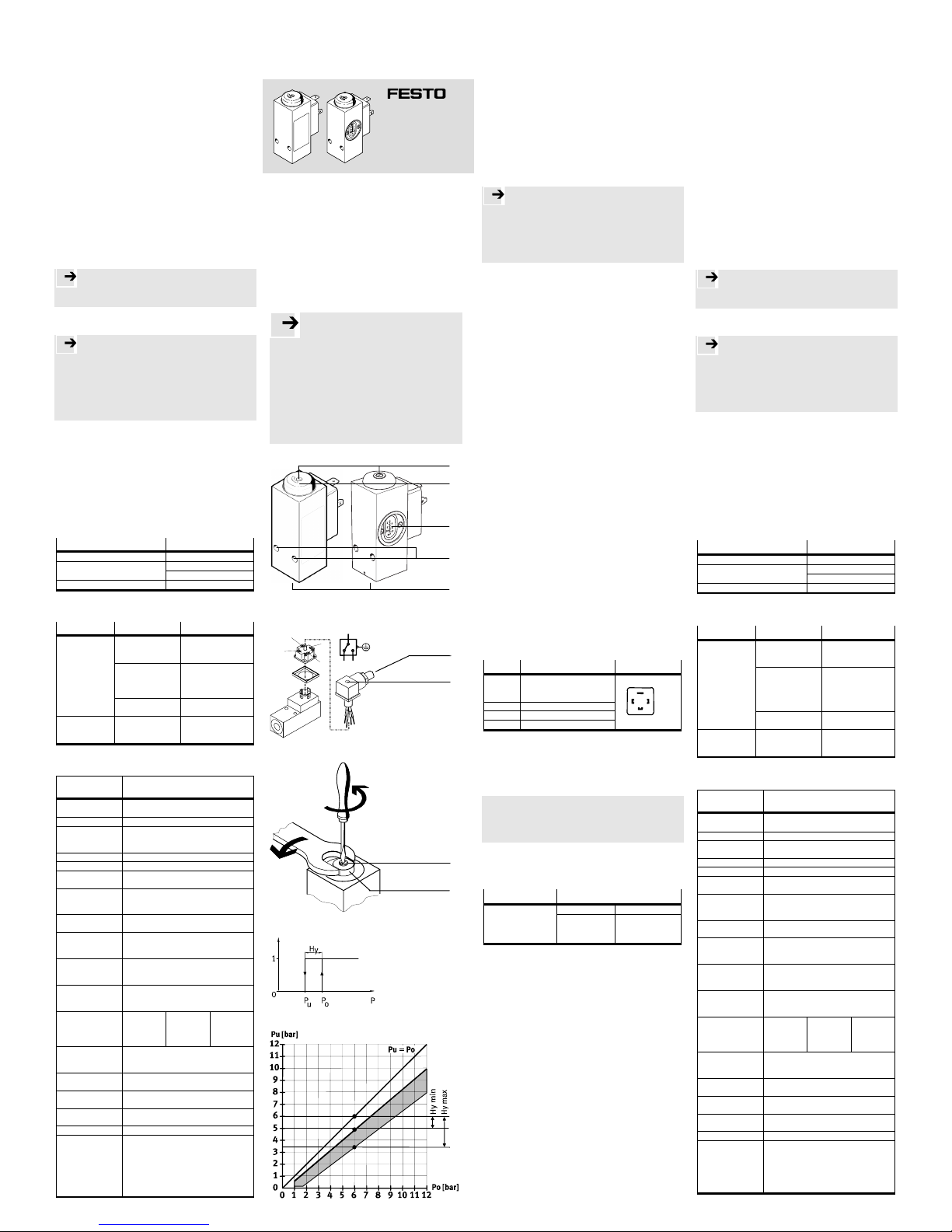
Type PEV-1/4-B; PEV-1/4-B-OD; PEV-1/4-SC-OD
If correction of the switching point is necessary:
9. Repeat the following steps until the desired upper and
lower switching points are set:
– first set the lower switching point pu and turn adjusting
screw 4, then
– set the upper switching point po and turn adjusting
bolt 5.
In this way you can define in accurate steps the switching
point and the hysteresis.
10. Fasten protective cap 3.
Setting the switching point of the PEV-1/4-SC-OD:
• Turn adjusting screw 4until the desired upper switching
point is reached [see adjusting scale 6].
The hysteresis is then specified. The setting should be
checked under pressure.
5 Operation
With fluctuations in the medium temperature:
Please note
Note that the switching point is slightly influenced.
With medium temperatures less than 1 °C:
Please note
Avoid the dew point being reached.
If the dew point is reached, the membrane will ice up and
become stiff.
The characteristic values of the pressure switch will then be
modified.
Remedy: The dew point can be lowered if dried compressed
air is used.
6 Care and maintenance
• If the PEV-... is dirty, clean the exterior with a soft cloth.
All non-abrasive cleaning agents are permitted.
To compensate for deviations in the switching point after a
high number of switching cycles:
• repeat the switching point setting (see “Commissioning”).
7 Accessories
Designation Type
Screw connector CK-.../CN-...
PEV-1/4-WD-...-LED-...Connector socket
MSSD-C-4P
Mounting plate APL-2N-PEV
8. Eliminating faults
Fault Possible cause Remedy
Switching point too
high
Correct switching
point (see
“Commissioning”)
Hysteresis too
large (not with PEV-
...-SC-…)
When commissioning
set hysteresis at first
at minimum (see
“Commissioning”)
PEV does not
switch
Switch defective Return PEV-…
to Festo
No switching
signal given
Connection fault Check the electrical
connection assign-
ment of the PEV-…
9 Technical specifications
Type PEV-1/4-B [PEV-1/4-B-OD];
PEV-1/4-B-SC-OD
Part no. 10 773 [175250];
161760
Design mechanical pressure switch
Medium filtered, lubricated or non-lubricated
compressed air
(filter fineness min. 40 µm)
Mounting position as desired
Connection G ¼ (pneumatic)
Adjustable
switching pressure
1 … 12 bar
(status as supplied: 6 bar ± 0.5 bar)
Hysteresis adjustable [not with PEV-1/4-SC-OD]
(adjusting range see Fig. 5;
as supplied: 1.2 bar ± 0.3 bar)
Permitted
temperature range
-20 °C ... +80 °C. Dew point must not be
reached at <1 °C (air must be dried)
Operating voltage max. 125 V DC / max. 230 V AC
(note permitted voltage of connector
socket)
max. switching
current
5 A (ohmic load)
(measured operating current:
4 A ohmic load; 3 A inductive load)
min. load current 1 mA (24 V DC/AC);
10 mA (10 V DC/AC);
100 mA (5 V DC/AC)
Permitted contact
loading
- ohmic load
- inductive load
0 ... 230 V AC
5 A
0.5 A
0 ... 30 V DC
5 A
3 A
30 ... 125 V DC
0.4 A
0.025 A
Usage category AC 12/DC 12 (ohmic load)
AC 14/DC 13 (low electromagnetic load
and electromagnets)
Switching time at
6 bar
On: 1.5 ms (typical),
Off: 3 ms (typical)
Permitted switch-
ing frequency
max. 3,3 Hz
Protection class as
per EN 60529
IP 65 with correctly fitted connector
socket with cable
Reproducibility ± 3% at constant temperature
Materials:
- housing:
- plugs, contacts:
- seals,
diaphragms:
- micro switch
aluminium (coated), PC, PE
brass (chromium-plated/gold-plated)
NBR
silver-plated contacts
PEV-1/4-B(-OD)
PEV-1/4-SC-OD
Bedienungsanleitung Festo AG & Co. KG
Operating instructions Postfach
D-73726 Esslingen
Phone:
Original: de +49/711/347-0
0302c 386 354
Hinweis
de Einbau und Inbetriebnahme nur von autorisiertem
Fachpersonal, gemäß Bedienungsanleitung. Diese
Produkte sind ausschließlich zur Verwendung mit
Druckluft vorgesehen. Zur Verwendung mit anderen
Medien (Flüssigkeiten oder Gasen) sind sie nicht geeignet.
Notera
se Montering och idrifttagning får endast utföras av behörig
personal enligt bruksanvisningen. Dessa produkter är
endast avsedda för användning med tryckluft.
Produkterna är inte lämpade för användning med andra
medier (vätskor eller gaser).
PEV-1/4-B(-OD) PEV-1/4-SC-OD
Bild 1
MSSD-C-4P
4
2
3
11
2 3
4
Bild 2
Bild 3
Bild 4
Bild 5
Druckschalter ................................................ de (Teil 1)
Typ PEV-1/4-B; PEV-1/4-B-OD; PEV-1/4-SC-OD
1 Anwendung
Der Druckschalter PEV-... öffnet oder schließt einen
elektrischen Stromkreis beim Erreichen eines einstellbaren
Druckwertes (Wechsler). Durch das Ansteigen des Drucks
wird eine Kraft auf den Stößel ausgeübt. Die einstellbare
Federvorspannung bewirkt eine Gegenkraft. Beim
Überschreiten der Federkraft betätigt der Stößel einen
Mikroschalter, der die elektrischen Kontakte schließt bzw.
öffnet.
Der PEV-... wird bestimmungsgemäß eingesetzt zur
Erzeugung von Überwachungssignalen für Steuerungen.
2 Voraussetzungen für den Produkteinsatz
Hinweis
Durch unsachgemäße Handhabung entstehen
Fehlfunktionen.
Stellen Sie sicher, dass die Punkte dieses Kapitels stets
eingehalten werden.
Dies macht das Produktverhalten ordnungsgemäß und
sicher.
• Vergleichen Sie die Grenzwerte in dieser
Bedienungsanleitung mit Ihrem aktuellen Einsatzfall (z.B.
Drücke, Kräfte, Momente, Temperaturen).
Nur die Einhaltung der Belastungsgrenzen ermöglicht ein
Betreiben des Produkts gemäß der einschlägigen
Sicherheitsrichtlinien.
• Sorgen Sie für Druckluft mit ordnungsgemäßer
Aufbereitung.
• Beachten Sie die Vorschriften für Ihren Einsatzort z.B. von
Berufsgenossenschaft oder nationaler Institutionen.
• Entfernen Sie die Verpackungen.
Die Verpackungen sind vorgesehen für eine Verwertung
auf stofflicher Basis (Ausnahme: Ölpapier = Restmüll).
• Berücksichtigen Sie die Umweltbedingungen vor Ort.
• Berücksichtigen Sie die Warnungen und Hinweise
– am Produkt und
– in dieser Bedienungsanleitung.
• Verwenden Sie das Produkt im Originalzustand ohne
jegliche eigenmächtige Veränderung.
3 Einbau mechanisch
Bei Bedarf:
• Drehen Sie Schrauben zur Befestigung (M5) in die
Durchgangsbohrungen 2.
Einbau pneumatisch
• Verschlauchen Sie den PEV-... mit dem Druckluftanschluss
1 G 1/4 (Anzugsdrehmoment: max. 20 Nm) mit einer
Anschlussverschraubung (z.B. Typ CK-...).
Einbau elektrisch
• Verwenden Sie eine Anschlussdose laut Zubehör.
Die Anschlussdose MSSD-C-4P ist bei PEV-1/4-B im
Lieferumfang enthalten.
• Stellen Sie sicher, dass das Kabel folgendermaßen verlegt
ist:
– quetschfrei
– knickfrei
– dehnungsfrei.
• Verkabeln Sie die Anschlussdose mit einem Kabel
(Litzenquerschnitt: 0,5 mm2) wie folgt:
Pin-Nr. Anschlüsse Pin-Belegung
1 Schaltspannung:
AC 0 ... 250 V
DC 0 ... 125 V
2 Öffner Ausgang
3 Schließer Ausgang
4 Erdung
Das maximale Anzugsdrehmoment der
Befestigungsschraube beträgt 0,6 Nm (handfest).
4 Inbetriebnahme
• Beachten Sie, dass die Einstellschraube 4nur beim
Drehen gegen den Uhrzeigersinn einen Anschlag hat.
Definition
Schaltverhalten eines Druckschalters (siehe Bild 4):
oberer Schaltdruck: po
unterer Schaltdruck: pu
Hysterese: Hy
Zur Schaltpunkteinstellung des PEV-1/4-B(-OD):
1. Entfernen Sie die Schutzkappe 3.
2. Drehen Sie die Einstellelemente bis zum Anschlag wie
folgt (Grundstellung):
Einstellschraube 4Einstellbolzen 5 [SW11]
Po >3 bar Po <3 bar
gegen den
Uhrzeigersinn
(unterer Schaltdruck
pu)
im Uhrzeiger-
sinn (max.
Hysterese)
gegen den
Uhrzeigersinn
(min. Hysterese)
3. Verkabeln Sie die elektrischen Anschlüsse Pin 1 und Pin 2
(siehe Einbau elektrisch) mit einem Durchgangsprüfer.
4. Belüften Sie den PEV-... mit dem gewünschten unteren
Schaltdruck puu(z.B. 6 bar).
Dazu ist ein Kontrollmanometer erforderlich.
Der Durchgangsprüfer geht in Ausgangsstellung.
5. Drehen Sie die Einstellschraube 4im Uhrzeigersinn, bis
der PEV-... schaltet (unterer Schaltdruck erreicht).
Eine Umdrehung entspricht einer Veränderung des
Schaltdrucks von ca. 1,3 bar.
Der Durchgangsprüfer reagiert.
Zur Hystereseeinstellung des PEV-1/4-B(-OD) (Bild 4 und 5):
6. Drehen Sie den Einstellbolzen 5(SW 11) im Uhrzeigersinn
bis zum Anschlag (max. Hysterese; bei po >3 bar bereits
eingestellt). Der Durchgangsprüfer bleibt unverändert.
7. Beaufschlagen Sie den PEV-... mit dem oberen
Schaltdruck po (unterer Schaltdruck pu plus gewünschte
Hysterese Hy [siehe hierzu Diagramm in Bild 5]).
Der Durchgangsprüfer bleibt unverändert.
8. Drehen Sie den Einstellbolzen 5(SW 11) gegen den
Uhrzeigersinn bis der PEV-... schaltet (oberer Schaltdruck
po erreicht). Der eingestellte untere Schaltdruck bleibt
annähernd unverändert.
Der Durchgangsprüfer geht in Ausgangsstellung.
Druckschalter.................................................de (Teil 2)
Typ PEV-1/4-B; PEV-1/4-B-OD; PEV-1/4-SC-OD
Bei Bedarf einer Schaltpunktkorrektur:
9. Wiederholen Sie die nachfolgenden Schritte, bis ge-
wünschter oberer und unterer Schaltpunkt eingestellt sind:
– zuerst unteren Schaltdruck pu anlegen und
Einstellschraube 4drehen, dann
– oberen Schaltdruck po anlegen und
Einstellbolzen 5drehen.
Dadurch präzisieren Sie schrittweise Schaltpunkt und
Hysterese.
10. Befestigen Sie die Schutzkappe 3.
Zur Schaltpunkteinstellung des PEV-1/4-SC-OD:
• Drehen Sie die Einstellschraube 4bis der gewünschte,
obere Schaltpunkt eingestellt ist [siehe Einstellskala 6].
Die Hysterese ist dann vorgegeben. Die Einstellung sollte
unter Druck überprüft werden.
5 Bedienung und Betrieb
Bei Schwankungen der Mediumstemperatur:
Hinweis
Beachten Sie, dass der Schaltpunkt geringfügig beeinflusst
wird.
Bei Mediumstemperatur kleiner 1 °C:
Hinweis
Vermeiden Sie, dass der Taupunkt erreicht wird.
Bei Erreichen des Taupunkts vereist die Membrane und wird
steifer.
Dadurch ändern sich die Kennwerte des Druckschalters.
Abhilfe: Der Taupunkt kann durch getrocknete Druckluft
gesenkt werden.
6 Wartung und Pflege
• Reinigen Sie bei Bedarf den PEV-... außen mit einem
weichen Lappen. Zulässige Reinigungsmedien sind alle
werkstoffschonenden Medien.
Zum Ausgleich von Schaltpunktabweichungen bei hohen
Schaltspielzahlen:
• Wiederholen Sie die Schaltpunkteinstellung (siehe
Inbetriebnahme).
7 Zubehör
Bezeichnung Typ
Anschlussverschraubung CK-.../CN-...
PEV-1/4-WD-...-LED-...Anschlussdose
MSSD-C-4P
Montageplatte APL-2N-PEV
8. Störungsbeseitigung
Störung Mögliche Ursache Abhilfe
Schaltpunkt zu
hoch
Schaltpunkt
korrigieren (siehe
Inbetriebnahme)
Hysterese zu groß
(nicht bei PEV-...-
SC-...)
Hysterese bei Inbe-
triebnahme zunächst
auf Minimum
einstellen (siehe
Inbetriebnahme)
PEV schaltet
nicht
Schalter defekt PEV-... zu Festo
schicken
Schaltsignal wird
nicht
ausgegeben
Anschlussfehler Überprüfen Sie die el-
ektrische Anschluss-
belegung des PEV-...
9 Technische Daten
Typ PEV-1/4-B [PEV-1/4-B-OD];
PEV-1/4-B-SC-OD
Teile-Nr. 10 773 [175250];
161760
Bauart mechanischer Druckschalter
Medium gefilterte Druckluft, geölt oder ungeölt
(Filterfeinheit min. 40 µm)
Einbaulage beliebig
Anschluss G 1/4 (pneumatisch)
Einstellbarer
Schaltdruck
1...12 bar
(Lieferzustand: 6 bar ± 0,5 bar)
Hysterese einstellbar [nicht bei PEV-1/4-SC-OD]
(Einstellbereich siehe Bild 5;
Lieferzustand: 1,2 bar ± 0,3 bar)
Zul.
Temperaturbereich
-20 °C ... +80 °C. Taupunkt darf bei <1 °C
nicht erreicht werden (Luft trocknen)
Betriebsspannung max. DC 125 V / Max. AC 230 V
(zul. Spannung der Anschlussdose
beachten)
Max. Schaltstrom 5 A (ohmsche Last)
(Bemessungsbetriebsstrom:
4 A ohmsche Last; 3 A induktive Last)
Mindestlaststrom 1 mA (DC/AC 24 V);
10 mA (DC/AC 10 V);
100 mA (DC/AC 5 V)
Zul. Kontakt-
belastung
– ohmsche Last
– induktive Last
0 ... 230 V AC
5 A
0,5 A
0 ... 30 V DC
5 A
3 A
30 ... 125 V DC
0,4 A
0,025 A
Gebrauchs-
kategorie
AC 12/DC 12 (ohmsche Last)
AC 14/DC 13 (kl. elektromagnetische Last
und Elektromagnete)
Schaltzeit bei 6 bar Ein: 1,5 ms (typisch),
Aus: 3 ms (typisch)
Zulässige
Schalthäufigkeit
max. 3,3 Hz
Schutzart nach
EN 60529
IP 65 bei ordnungsgemäß montierter
Anschlussdose mit Kabel
Reproduzierbarkeit ± 3% bei konstanter Temperatur
Werkstoffe:
- Gehäuse:
- Stecker, Kontakte:
- Dichtungen,
Membrane:
- Microschalter:
Aluminium (beschichtet), PC, PE
Messing (verchromt/vergoldet)
NBR
Silberkontakte
0,6 Nm
Ø 6 ... 8 mm