Oksys ECOS-150 User manual

Use and Instruction Manual
Ecos-150 sw 1.x.x - ver. 1.0
Service station for A/C systems
ECOS-150

Index
1. General information for the user.............................................................................................................3
1.1 Preliminary instructions/proper use..................................................................................................3
1.2 General safety regulations ..............................................................................................................3
1.2.1 Warning icons used in the present manual...............................................................................4
1.2.2 Safety devices..........................................................................................................................4
1.3 Scrapping of the unit........................................................................................................................4
2. Installation and preparing for use...........................................................................................................5
2.1 Unpacking and checking of the unit.................................................................................................5
2.1.1 Checking the accessories delivered with the unit.....................................................................5
2.2 Preparing for use.............................................................................................................................5
2.2.1 Removal of load cell blocking device........................................................................................5
2.2.2 Oil level checking of vacuum pump..........................................................................................5
2.2.3 Connection of tubes and leak test ...........................................................................................6
2.2.4 Filling of internal bottle .............................................................................................................6
2.2.5 Connecting to power feeding ...................................................................................................6
2.2.6 Position on an even surface.....................................................................................................6
3. Use.........................................................................................................................................................7
3.1 Preliminary checks...........................................................................................................................7
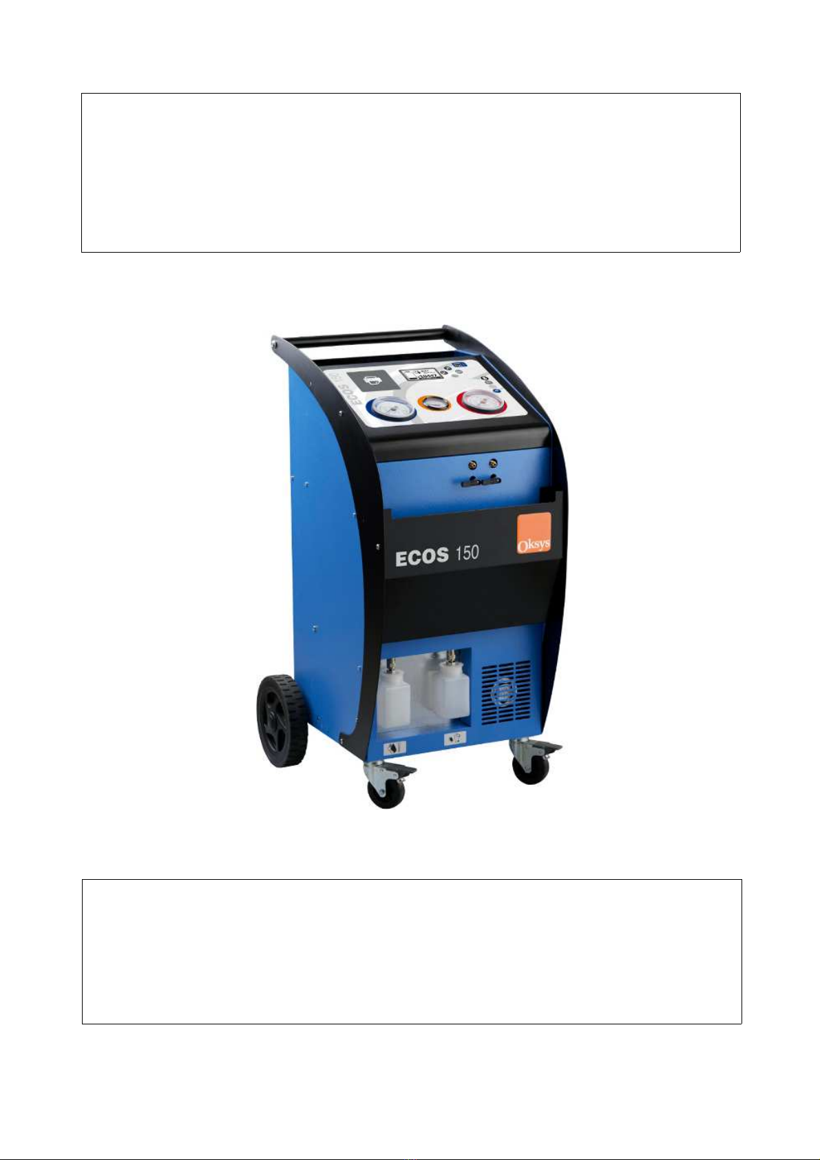
3.2 Description of the unit......................................................................................................................7
3.3 General description of the working cycles........................................................................................9
3.3.1 Release of Non-Condensable Gases.......................................................................................9
3.4 Analytical description of the working cycles....................................................................................10
3.4.1 Model choice through the internal DATABASE ......................................................................10
3.4.2 MANUAL /AUTOMATIC mode ...............................................................................................10
3.4.2.1 Starting an automatic working cycle ...............................................................................11
3.4.2.2 Recovery ........................................................................................................................11
3.4.2.3 Vacuum ..........................................................................................................................12
3.4.2.4 Leak test under vacuum .................................................................................................12
3.4.2.5 Oil injection into A/C system ...........................................................................................12
3.4.2.6 Dye injection into A/C system (optional).........................................................................13
3.4.2.7 Refrigerant gas recharging into A/C system ...................................................................13
3.4.3 Accessory functions ...............................................................................................................14
3.4.3.1 Self recycling..................................................................................................................14
3.4.3.2 Recharging of internal gas tank .....................................................................................14
3.4.3.3 Load cell test ..................................................................................................................15
3.4.3.4 Printing of refrigerant management report .....................................................................15
4. Options Setting ....................................................................................................................................16
4.1 Printing options of the recovered fluid ...........................................................................................16
4.2 Setting of recovery options ............................................................................................................16
5. Basic parameter setting and information .............................................................................................17
5.1 Hoses setting ...............................................................................................................................17
5.2 Information and statistics in use for the unit ..................................................................................18
6.Ordinary maintenance...........................................................................................................................18
6.1 Filter replacement..........................................................................................................................18
6.2 Oil replacement of vacuum pump...................................................................................................18
7. Technical data.......................................................................................................................................19
8. Declaration of conformity.....................................................................................................................20
Ecos-150 sw 1.x.x - ver. 1.0
Page 2/20

1. General information for the user
1.1 Preliminary instructions/proper use
The present recycling and recharging unit for A/C systems is meant for commercial purposes and is thought
to be used by trained personnel only being aware of the principles of refrigeration, conscious of the hazards
which may derive from equipment working under pressure with substances at very low boiling temperature.
We advise to read the present instruction manual carefully and to strictly comply with the given
information, paying particular attention to the safety regulations. We shall decline any
responsibility resulting from the improper use of the equipment, use for purposes other than
those described in the present operating manual, incorrect operation, damages resulting from
external influences.
Always keep the unit in vertical position in order to avoid oil leaks and the compressor to be damaged.
1.2 General safety regulations
✔Read the instructions for use careful before starting to operate with this Aircon service unit;
✔
Follow the informations and the instructions
of the refrigerant manufacturer;
✔Observe any instructions on servicing vehicle aircon systems which apply at your company;
✔Use with R134a refrigerant indicated on the data plate (R-134a for Fast20X/Ecos20X; HFO-1234YF
for Fast20XYF);
✔Do not make modifications to the service unit;
✔Only employ original spare parts and accessories;
✔Use authorized additives or consumables only(ask for advice from an authorized reseller);
✔Before starting the machine first check each time whether the charging hoses and the quick
couplers are undamaged and are not leaking;
✔Recover refrigerant from the hoses before releasing the quick connections;
✔Do not leave the unit unattended when switched on; Use the main switch to switch off the unit after
its use;
✔Always wear personal safety equipment ( gloves and protective goggles);
✔Avoid inhaling the refrigerating gas;
✔Avoid the contact with the skin by refrigerating gas, danger of freezing;
✔Never abandon the refrigerating gas in the environment;
✔Do not use the unit in potentially explosive environments; (for instance: battery charging rooms);
✔Do not smoke whilst using the recharging unit;
✔During the operations, locate the unit on a flat and leveled surface;
✔Do not use the unit near flames or sources of heat; at high temperatures the refrigerating gas can
generate poisonous substances for inhalation;
✔Do not use the unit in very humid and wet environments or in the rain;
✔Use the unit in airy environments;
✔During maintenance operations disconnect the unit from the electrical power.
✔Avoid removing the connecting hoses if not necessary; in case always make a vacuum in the
hoses before using again;
Ecos-150 sw 1.x.x - ver. 1.0
Page 3/20

✔Maintenance operations have to be carried out by specialized and authorized personnel.
✔Do not violate for any reason at all the safety devices the unit is equipped with, like the high
pressure valve of the internal reservoir.
✔Do not fill compressed air in the lines of the service unit or in the vehicle aircon system (a mixture of
air and refrigerant can be flammable or explosive);
Please be aware that whatsoever damages due to a wrong or improper use of the recharging station will not
be covered by our warranty. Consumables like packing and seals for hoses and quick couplings, fuses and
damages occurred during transport are not part of the warranty.
1.2.1 Warning icons used in the present manual
Caution! Connect to
230V socket
50Hz
Wear gloves
when handling
refrigerants
Wear goggles
when handling
refrigerants
Protect against
rain
Read
instruction
manual
carefully
1.2.2 Safety devices
A) Pressure release valves on internal gas tank: releases pressure if 16 Bar are exceeded in the gas tank.
1.3 Scrapping of the unit
-
Do not treat the unit as mixed solid waste for scrapping but take it to pieces ( waste separation).
- Refer to the specific collection points for waste of electric and electronic devices (AEE), according to the
relevant CEE RAEE 2002/95/EC, 2002/96/EC2003/108/EC regulation.
- The vacuum pump and the containers of new and used oil contain mineral and synthetic oil. Therefore the
specific regulations for scrapping have to be followed. The same procedure has to be followed for the
refrigerant gas residual in the storage bottle. The exhaust oil drained from the pump is a specific waste and
has to be collected according to the relevant regulations in force.
Ecos-150 sw 1.x.x - ver. 1.0
Page 4/20

2. Installation and preparing for use
2.1 Unpacking and checking of the unit
Check the integrity of the packaging to exclude damages occurred during transport. Check the entirety of
the equipment and of the relevant accessories. Not conformities, if any, have to be pointed out immediately
and written down on the transport documents
2.1.1
Checking the accessories delivered with the unit
2.2 Preparing for use
2.2.1 Removal of load cell blocking device
Before using the unit for the first time remove the safety screw which is screwed to the tank load
cell for protection during transport(see fig. 1). It is recommended to check the regular functioning
of the load cell, for example by hooking a known weight to the bottle to check the corresponden-
ce with the weight shown on the display (see relevant paragraph).
1Rivet nut to fix the load cell during transport
2Threaded hole to fix the calibration hook to the
load cell
3Fixing bolts of the load cell
2.2.2 Oil level checking of vacuum pump
Check the level of hydraulic oil in the vacuum pump and, if necessary, fill up to the level (about half of the
spy glass)
Ecos-150 sw 1.x.x - ver. 1.0
Page 5/20
Half of the level

2.2.3 Connection of tubes and leak test
Connect the charging hoses to the unit (high pressure = RED, low pressure = BLUE). Make sure that the
quick couplings are in position “CLOSED”.
Carry out a vacuum cycle of one/two minutes followed by a leak test under vacuum. The above procedure
avoids that air residuals are left in the hoses and checks for eventual leaks. (see the relevant instructions)
The vacuum and the following leak test the test should be repeated whenever the charging hoses could
have been contaminated with air.
Check if the setting relevant to the length of the hoses is correct (select “OPTIONS AND SETTINGS” then
“HOSE LENGTH” and modify if needed , by means of the buttons “UP” and “DOWN”
If the hose length is set to “0” (zero), at the end of the working cycle, the unit will not
calculate the gas remaining in the hoses at the end of the working cycle. The user has to
suction the gas residuals in the A/C system of the vehicle, at the en of the working cycle.
Note: in case of a pressure test which is not preceded by a standard working cycle, the user has to recover
the gas residuals in the vehicle A/C sytem, regardless to thehose length setting.
2.2.4 Filling of internal bottle
The unit is delivered with the empty internal gas bottle for safety reasons. It is therefore necessary
to fill the bottle with a refrigerant g quantity not lower than 2 Kg and not higher than eighty percent
of the maximum nominal capacity of the reservoir (this percentage may vary according to local
safety rules). In order to fill the internal tank please follow the relevant instructions of the present manual.
2.2.5 Connecting to power feeding
Connect to proper power feeding according to the unit's technical specifications
2.2.6 Position on an even surface
During the operations, the unit must be located on a flat and leveled surface in order to correclty
perform the weight measurements and in order to comply to the safety rules.
Ecos-150 sw 1.x.x - ver. 1.0
Page 6/20

3. Use
3.1 Preliminary checks
Connect the feeding cable to the mains (220V AC single phase) and turn on the main switch.
•Check that the refrigerant used by the A/C system to be serviced is the one the service unit is
intended for R134a
•Check oil levels (vacuum pump and new oil reservoir).
•After having turned on the unit, check the level of the refrigerant in the internal reservoir.
3.2 Description of the unit
Ecos-150 sw 1.x.x - ver. 1.0
Page 7/20
4 6 7 8
5
3
2
1
12
910
11
15
14
16
17
18
13

Legend
1High pressure gauge For the inspection and diagnosis of the A/C
system
2Tank pressure gauge To check the pressure inside the gas storage
reservoir.
3Low pressure gauge For the inspection and diagnosis of the A/C
system and for the control of the vacuum.
4Thermal printer (OPTIONAL) (OPTIONAL) prints a report on the carried out
cycles
5 Graphic display Visualizes the operations of the unit
6 Button “Down” To browse the menus or increase the values of
the various parameters
7 Button “UP” To browse the menus or decrease the values of
the various parameters
8 USB port Connection port for databank update
9 Button “EXIT” To select and confirm the different functions, or
to enter the following menu
10 Button “ENTER” Interrupts any whatsoever operation, to exit and
return to the previous menu
11 LP (blue) and HP (red) taps Open /close the HP and LP lines
12 New oil bottle New compressor oil storage
Dye bottle (OPTIONAL) Fluorescent dye bottle can be added as an
optional
13 Used oil bottle Drained oil bottle
14 Main switch Switches on and off the unit
15 Identification plate Shows the machine data
16 Access to safety valve Allows to access the max pressure valve
17 Access to vacuum pump Allows the vacuum pump inspection
18
Max pressure valve
Automatically releases pressure if max pressure
is reached. Allows to manually release NCG
gases, if present
Ecos-150 sw 1.x.x - ver. 1.0
Page 8/20

3.3 General description of the working cycles
After switching on the unit, the display shows the model number and the SW version for few seconds:
Following screen is then displayed including information on the status of the unit:
a) the weight of the refrigerant in the internal tank
b) the temperature of the gas in the tank and
c) the corresponding (theoretic) pressure value of R134a
d) the currnt date and time
Icon Meaning
Refrigerant level in the internal tank and weight value
Temperature of the refirgerant in the internal tank and (theoretical) gas max presssure value
3.3.1 Release of Non-Condensable Gases
If the value of the (theoretical) gas pressure (see above point c) -
calculated on the base of the gas temperature measured by the
temperature probe - is significantly higher than the actual pressure
of the gas in the tank (you may read its value by means of the tank
pressure gauge, see above fig.n.2) the refrigerant is mixed with
non-condensable gases. (NCG).The unit automatically releases the
gases during the vacuum phase through the NG release valve You
may also pull the ring on the max pressure valve to release the
NCG's until the theoretical and the actual pressure comply.
Note: if the value on the pressure gauge, on the opposite, is lower
than the theoretical one, the gas quantity in the tank is too low.
Ecos-150 sw 1.x.x - ver. 1.0
Page 9/20
18
bc
d
a

3.4 Analytical description of the working cycles
3.4.1 Model choice through the internal DATABASE
Select the working mode through DATABASE and press ENTER
Press ENTER browse the list of car
types and versions by
means of the buttons UP
and DOWN
After the final selection, the unit shows the same display as in the “ MANUAL -AUTOMATIC mode” (see
here following) but indicates the recommended refrigerant quantity for the specific car model of your choice.
By selecting “START” and pressing ENTER, the unit starts an automatic working cycle, as explained more in
detail hereafter. Otherwise is also possible to select the single working cycles, and press ENTER in order to
perform that particular cycle only.
3.4.2 MANUAL /AUTOMATIC mode
Select MANUAL in order to reach the working cycle selection. All working cuclescycles can be done
automatically in one step by pressing on START, or you can perform the single working cycles one by one
Press ENTER
browse the differnet
working cycles by
means of the buttons UP
and DOWN
The unit displays following information :
1. Current vacuum time / leak test time settings
2. Current oil quantity setting
3. Current gas charging setting
Using the buttons “UP” and “DOWN” you may choose the desired function and press ENTER to start
Icon Meaning
START: immediate start of AUTOMATIC and complete working cycle according to the
parameters shown on display (all cycles performed at one time) (FOLLOWS)
Ecos-150 sw 1.x.x - ver. 1.0
Page 10/20
3
2
1

Icon Meaning
RECOVERY: immediate start of refrigerant gas recovery from the vehicle
VACUUM: access to the vacuum settings or start of a VACUUM cycle
LEAK TEST: Access to vacuum test settings or start of VACUUM TEST cycle
OIL INJECTION: Access to quantity setting and start of NEW OIL INJECTION cycle.
DYE INJECTION: access to quantity setting and start of DYE LINJECTION cycle (optional)
Access to quantity setting and/or start of REFRIGERANT CHARGINGcycle in the vehicle
3.4.2.1 Starting an automatic working cycle
By selecting START and pressing ENTER the unit automatically carries out all working cycles, according to
the parameters shown on the display.
Before every cycle (which includes a gas charging) you will be first asked to choose the gas charging mode
Choose the right side with
help of the buttons UP and
DOWN, open the
relevant tap/s (see fig. n.
11) and press ENTER
Both sides open High pressure only open Low pressure only open
In case a vehicle model has been selected from the data bank the various parameters are already indicated
under their relevant icon, otherwise the parameters have to be set manually. The working cycles can be
performed one by one or all together. The performed cycles are:
a) Recovery of refrigerant gas form the vehicle
b) Oil separation from recovered refrigerant and draining into proper container
c) Vacuum and d) Leak test under vacuum
e) New oil charging and f) Charge of dyeing substances (optional feature)
g) Final gas recharging into the vehicle
Note: in order to change a single parameters of an automatic cycle, browse the menu until you reach the
cycle whose value has to be changed , press ENTER, change the value and press EXIT to return to START.
If, on the opposite, you want to immediately perform the single cycle only, press ENTER
3.4.2.2 Recovery
By selecting RECOVERY and pressing ENTER the unit carries out the refrigerant recovery from the A/C
system and discharges the exhaust oil.
Press ENTER
Ecos-150 sw 1.x.x - ver. 1.0
Page 11/20
2
1

1) Refrigerant currently recovered from the vehicle
2) Refrigerant pressure in the vehicle
In order to assure a perfect recovery and oil separation, the unit modulates the gas flow in relation to its
pressure. The ecovery cycles may therefore be alternated by intervals. The operation is followed by a
waiting period to check for any gas residuals in the system. The length of this test tim can be set in the
OPTIONS menu. The unit then drains any oil recovered during the recovery phase.
3) Time left to the end of the test time
4) Oil drain duration
3.4.2.3 Vacuum
By selecting VACUUM it will be possible to set the duration of the vacuum.
Press ENTER Decrease/increase the
vacuum length by means
of the buttons UP and
DOWN
Press EXIT to return to START If , on the oposite, you press ENTER again the unit checks if there is no
pressure in the lines and, starts the vaccum The vacuum cycle is automatically followed by a leak test cycle
under vacuum according to the set parameters )
Note: the unit gives out acoustic signals until a good vacuum level is reached. In case of a
remarkable leakage, when this level is never reached, the unit continues the signal and therefore
warns the operator.
3.4.2.4 Leak test under vacuum
By selecting LEAK TEST , it will be possible to set the duration of the leak test under vacuum.
Press ENTER Decrease/increase the
vacuum test length by
means of the buttons UP
and DOWN
Press EXIT to return to START By pressing the button ENTER again, the unit would carry out a capacity test
under vacuum according to the parameters set before.
(select this option only if the vacuum in the system has already been carried out)
3.4.2.5 Oil injection into A/C system
By selecting icon OIL INJECTION, you access the oil injection selection menu
Ecos-150 sw 1.x.x - ver. 1.0
Page 12/20
4
3

Press ENTER Decrease/increase the oil
quantity by means of the
buttons UP and DOWN
It is possible to set the oil quantity to be injected into the A/C system. It is suggested to set a quantity of
10/15 g for a medium sized A/C system. Press EXIT to return to the main menu. By pressing the button
Enter, the unit would immediately inject the desired oilquantity.
Always check the presence of oil or dye in the relevant container BEFORE starting the procedure.)
Note(1): it could be necessary to adjust the oil viscosity parameter (see menu “settings”, here following) if you notice the charged oil
quantity is not correct. This could be due to particular environment conditions; the default settings allows accurate oil charging for
medium viscosity oil at a temperature of 18-22°C.
Note(2):
in order to charge oil in the A/C systems always previously make a vacuum cycle.
Note(3):
the oil charging system is designed in order to charge small quantities of oil recovered from the
vehiclein during the recovery cycle. It is not recommended in case of charging bigger quantities.
3.4.2.6 Dye injection into A/C system (optional)
By selecting the icon and DYE INJECTION it is possible to set the quantity of dye liquid to be injected into
the A/C system. The procedure is similar to that used for the oil charging (see aboveI. Once set the
parameters, press EXIT as by pressing the button Enter again, the unit would immediately open the valve
for the necessary time to inject the desired quantity.
Always check the presence of oil or dye in the relevant container BEFORE starting the procedure.
3.4.2.7 Refrigerant gas recharging into A/C system
By selecting RECHARGING it is possible to set the refrigerant quantity to be injected into the A/C system (It
is furthermore be possible to derive the quantity from a data bank as shown above)
Press ENTER Decrease/increase the
gas quantity by means of
the buttons UP and
DOWN
At the end of the cycle, the operator is requested to close the quick couplings on the vehicle in order to start
the recovery cycle of gas residuals in the connecting tubes.
Disconnect,
press ENTER
1) Current hose pressure
Note
(1)
If, on the opposite you wish to suction the gas residuals of the hoses into the vehicles' A/C system,
you should have set the hose length to the value “0” (see hereunder p “Setting the hose length” )
Note
(2)
The refrigerant charging is carried out thanks to the pressure difference between the tank and the
Ecos-150 sw 1.x.x - ver. 1.0
Page 13/20
1

A/C system. The unit automatically increases the tank temperature to increase its pressure during the
vacuum time It is therefore advisable to carry out a recharging only after having carried a reasonable
vacuum cycle.
Note
(3)
in order to recharge the A/C system it is necessary that the internal bottle contains a sufficient gas
quantity. If not enough gas is contained in the tank, the unit displays a warning message (to refill the internal
gas tank see the relevant paragraph hereunder)
3.4.3 Accessory functions
By selecting the icon ACCESSORIES you will access the accessory functions menu
Press ENTER Browse the various
funtions by means of the
buttons UP and DOWN
Icon Meaning
SELF RECYCLING: access to the internal flushing cycle of the unit with refrigerant
TANK RECHARGING Start of internal bottle recharging with R134a
LOAD CELL TEST: access to the display relevant to the various load cells test
REPORT PRINT: report printing on recovered refrigerant and oil quantity and injected by the
unit
3.4.3.1 Self recycling
Press ENTER Decrease/increase the
recycling time by means
of the buttons UP and
DOWN
By selecting SELF RECYCLING an automatic procedure of internal recycling with refrigerant is started. The
refrigerant circulates through the internal oil separator and the dryer filter of the unit in order to clean the
lines from oil ,moisture or dirt residuals. A duration of min 15 min is suggested to obtain proper cleaning.
3.4.3.2 Recharging of internal gas tank
Press ENTER Decrease/increase the
gas quantity to be
chraged in the internakl
tank by means of the
buttons UP and DOWN
When the refrigerant level in the internal bottle reis too low, the units displays a warning message and it is
necessary to recharge the bottle. Connect a R134a gas bottle to the high pressure service tube (red)
Ecos-150 sw 1.x.x - ver. 1.0
Page 14/20

Select TANK RECHARGING and set the gas quantity to be taken out from the external bottle and press
ENTER The unit carries out the recharging into the internal reservoir, signalizing by intermittent tones the
end of the operation.
3.4.3.3 Load cell test
By selecting LOAD CELL TEST you may test the current accuracy of balance of the gas tank. The unit
displays on the first row the weight of the applied sample weight and, onsecond row, the total value read on
the cell, both in analogic and in digitale form ( botttom)
Press ENTER
1) Relative weight (weight of the sample for test purppose)
2) Currrent weight of the tank
3) Digital value
Hook a smaple weight to the load cell (balance) in order to test the weight measurement
(in order to calibrate the load cell, follow the specific instructions in the service manual)
3.4.3.4 Printing of refrigerant management report
Press ENTER
1) “From” - “To” values
2) Data regarding the gas and oil quantities innthe time period
Select REPORT PRINT to print (if a printer is available on the unit) a report including:
a) total recovered refrigerant quantity (starting from the last counter reset)
b) total recharged refrigerant quantity (starting from the last counter reset)
c) total recharged oil quantity (starting from the last counter reset)
At the end of the print out, the user is required to choose if the counters have to be reset to “0” or not.
Press on ENTER to reset all counters or “EXIT” to maintain the existing data
Ecos-150 sw 1.x.x - ver. 1.0
Page 15/20
Hook a sample weight to the
load cell to test it
2
3
2
1
1

4. Options Setting
Select OPTIONS, to recall the optional functions :
Press ENTER Browse the different
functions by means of
the buttons UP and
DOWN
Icon Meaning
YES
PRINT FLIUD: printing option of recovered fluid yes/no
MAX RECOVERY: setting of the “Max recovery” options
4.1 Printing options of the recovered fluid
Gives the opportunity to choose, if to print or not the recovered fluid quantity among the other working cycle
data which are printed by default (recovered quantity yes/no option)
Press ENTER Choose YS or NO by
means of the buttons UP
and DOWN
4.2 Setting of recovery options
To increase the settings of the recovery in order the unit to carry out the utmost refrigerant recovery from the
vehicle (Note: he setting of Max recovery mode may result in an increase of the recovery time)
Press ENTER Brows the options by
means of the buttons UP
and DOWN
The “recovery test” time is the time during which – once the compressor of the unit has been stopped – the
unit checks if there is a pressure increase in order to start a recovery procedure once again.
Press ENTER Increase the
durationsetting by means
of the buttons UP and
DOWN (min 3 min.)
With “additional recovery” it is possible to set the duration of an additional recovery to be made after the
“standard” recovery procedure has finished.
Press ENTER Increase the extra
recovery time by means
of the buttons UP and
DOWN
Ecos-150 sw 1.x.x - ver. 1.0
Page 16/20

5. Basic parameter setting and information
By selecting SETUP, the functional parameter settings is visualized
Press ENTER Browse the various
options by means of the
buttons UP and DOWN
Icon Meaning Description
DATE /TIMESetting of date and
time
It is possible to regulate date and time The set data are
automatically stored when you exit the menu
LANGUAGESetting of used
language
By selecting this option it is possible to choose the language
visualized on display Press ENTER to confirm and exit.
LCD SETTINGS To increase / decrease the contrast and the brilliance of the display
HOSES SETTING Setting of
used working tube length,
choice of gas residuals
treatment (suction into the unit
vs. suction in the A/C system)
Select to choose the length of the hoses. The default length is 3 m,
max length is 10 m
NOTE: If the hose length is set to “0” (zero), at the end of the
working cycle, the unit will lead the user to suction the gas
residuals in the A/C system of the vehicle, instead of
recovering them into the unit
OIL VISCOSITY Setting of ithe
viscosity of the oil to be injected
For the adjustment of the opening time of the oil injection valve
(according to higher/lower viscosity of oil to be injected and to the
environment temperature) .This regulation is only necessary for
models without oil scales. The default setting is a parameter of
100, it is possible to adjust (increase or decrease ) this value and,
consequently, the opening time of the oil solenoid valve.
File transfer
Selecting this option the unit is ready to receive the files of data
bank up-dates. The unit signalizes the receipt of the data. For the
use of the up-dating Software please refer to the specific
instructions
Information and statistics in use
for the unit
Displays informations and the software version of the unit as listed
below
5.1 Hoses setting
Select to choose the length of the hoses currently in use in order the unit to be able to calculate the
refrigerant quantity which remains in the charging hoses. The default length is 3 m, max length is 10 m
Press ENTER Increase the hose length
by means of the buttons
UP and DOWN
(set “0” to suction the gas
residuals in theA/C syst
NOTE: If the hose length is set to “0” (zero), at the end of the working cycle, the user will have to
suction the gas residuals in the A/C system of the vehicle, instead of recovering them into the unit.
Ecos-150 sw 1.x.x - ver. 1.0
Page 17/20

5.2 Information and statistics in use for the unit
The available information relevant to the use of the unit are:
Firmware: SW version in use
Service: last service carried out on the unit
Bottle: capacity of internal bottle
Hoses: gas residual quantity in the hoses at the end of charging
Press. switch: pressure value; by reaching this value the recovery cycle is interrupted
Vacuum switch: max pressure value before warning “system leakage” during the leak test cycle
Total recharges: number of total carried out recharges
Recovered fluid: total quantity of recovered refrigerant
Recharged fluid: Total quantity of refrigerant charged into A/C systems
Charged oil quantity: Total quantity of new oil t charged into A/C systems
Vacuum pump: using mode of vacuum pump
S/N:serial number of the unit
6.Ordinary maintenance
The replacement of the filters and the oil of the vacuum pump has to be carried out by skilled personnel. It is
advisable that the maintenance service be followed by an authorized centre in order to make sure that the
maintenance operations are carried out in a correct way so that the warranty of the product is not
interrupted. The unit registers service operations in order to monitor the working hours of the filters and the
vacuum pump oil , the software version installed in the unit and the data bank version (if available in your
model) These counters have to be reset by the service personnel.
6.1 Filter replacement
•Avoid the refrigerant to contaminate atmosphere.
•Recover the gas residuals left in the charging hoses and in the filter
•Replace with original filters
ATTENTION! The filters have to be mounted according to the flow direction
indicated by the arrow signed on the filters itself
6.2 Oil replacement of vacuum pump
1Oil drain screw plug
2Sight glass
3Air inlet
4Oil filling cap
5Exhaust fittings
6Vacuum pump information plate
- Check the oil level by means of the relevant sight glass (2). The level of the oil (when the pump is not
working) should be at the middle of the sight glass.
Ecos-150 sw 1.x.x - ver. 1.0
Page 18/20

- In order to replace the oil, remove the screw plug (1) switch on the pump for few seconds (max 5-10
seconds!) drain the oil in a container. Screw the oil drain plug in position again and add new oil by means of
the cap (4) until you reach the normal level (middle of the sight glass) Use specific hydraulic oil only to fill
into the vacuum pump! Put the oil filling cap (4) in position and switch on the pump for a final check.
- Replace the oil of the vacuum pump every 120 working hours, or, at least, once a year. By reaching the
max working time the unit will display the message “SERVICE REQUIRED to inform that it is necessary to
perform an ordinary maintenance service on the unit
IMPORTANT : the exhaust oil drained from the pump is a special waste and as such it has to be scrapped
according to the regulations in force.
Warning: switch off the unit and unplug from electrical socket before operating on the
vacuum pump. Electrical shock hazard!
7. Technical data
Model ECOS150
Allowed refrigerant R134a
Gas Tank (nominal capacity) 9 Kg / 20C°
7,6 l
Gas Tank : max pressure valve
setting
16 bar
NCG purge system manual / automatic
Working temperature 10C° - 40C°
Compressor 1.060W
Vacuum pump: flow rate 100/113l/min (50/60Hz)
Vacuum pump:
ultimate vacuum capacity
0,02 Mbar / 20 Pa
Electronic scale accuracy +/- 5 g
Service hoses length 2 x 3 m
Safety couplings 1 x HP + 1 x LP
Tension(V/Hz) 230/50-60Hz
Fuses 2 x 10A
Overall dimensions 545x520x950
Package dimensions 565x540x1110
Net weight/Gross weight 55/65
Via Dell'Albereto 33/B
50041 Calenzano (FI)
Italy
www.oksys.com in[email protected]
Tel.:+39 055 8990665
Fax +39 055 8990665
Ecos-150 sw 1.x.x - ver. 1.0
Page 19/20

8. Declaration of conformity
DECLARATION OF CONFORMITY
DICHIARAZIONE DI CONFORMITA'
(Community directives about Machinery, Low Voltage Electrical Devices and Electro-
magnetic Compatibility)
Oksys srl Via Dell'Albereto 33/B - 50041 Calenzano (FI) (Italy)
hereby declares that the following products:
dichiariamo che i seguenti prodotti:
R134 refrigerant recovery and recharge unit
Unità di recupero e ricarica refrigeranti R134
Model ECOS150 Code n. FKE150
Have been designed, manufactured and distributed meeting in full the essential requirements specified by
the following European Directives concerning safety of machinery, safety of low voltage electrical apparatus
and electro-magnetic compatibility:
È stata progettata, prodotta e distribuita in accordo totale con i requisiti essenziali specificati dalle seguenti
Direttive Comunitarie riguardanti la sicurezza dei macchinari, la sicurezza delle apparecchiature in bassa
tensione e la compatibilità elettro-magnetica.
MACHINERY DIRECTIVE
(Direttiva macchine)
(2006/42/CE);
LOW VOLTAGE DIRECTIVE
(Direttiva Bassa tensione)
(2006/95/CE);
ELECTROMAGNETIC COMPATIBILITY DIRECTIVE
(Direttiva Compatibilità Elettromagnetica)
(2004/108/CE)
The conformity is declared with reference to the following harmonized standards:
La conformità è dichiarata con riferimento alle seguenti norme armonizzate:
EN 61010-1:2010; EN 62233 :2008
EN 61000-6-1:2007; EN 61000-6-3:2007;
EN 61326-1:2007
EN 61000-3-2 :2006/A1:2009/A2:2009; EN 61000-3-3:2008;
The machines are built according to RoHS European Directive requirements
Le macchine sono costruite secondo le Direttive Europee RoHS
(2002/95/CE)
Calenzano, 26/05/2014
Ecos-150 sw 1.x.x - ver. 1.0
Page 20/20
Table of contents