Product variant Code Meaning
prepared for common supply manifold, vacuum port
with QS push-in fittings, exhaust port with open silencer
(-B-PO/-C-PO)
Pneumatic connections -PO
prepared for common supply manifold, vacuum port
with QS push-in fittings inch, exhaust port with open
silencer (-BN-PO)
-ON NO, normally open (vacuum generation)
-OE NO, normally open (vacuum generation) with ejector
pulse
-CN NC, normally closed (no vacuum generation)
Normal position of the
vacuum generator
-CE NC, normally closed (no vacuum generation) with eject-
or pulse
Electrical connection -N M12 plug (5-pin)
-1PD 1 switching output PNP, 2 switching inputs PNP, with
display
-2P 2 switching outputs PNP
-2N 2 switching outputs NPN
-PU 1 switching output PNP, 1 analogue output 0…10V
Vacuum sensor
-PI 1 switching output PNP, 1 analogue output 4…20mA
- bar (-B), InHg (-BN)
-B bar
-W InH20
Alternative vacuum display
-H InHg
Tab. 3 Overview of variants
5 Fast commissioning with factory settings
The vacuum generator is supplied with the following factory settings:
– Switching characteristics of the electrical output: threshold value comparator
– Switching element function of the electrical output: NO (normally open)
– Switching point (SP): -0.4bar
– Fixed hysteresis (HYS): 20mbar
1. Mount the vacuum generator è 7 Assembly.
2. Connect the pneumatics for the vacuum generator
è 8.1 Pneumatic installation.
3. Connect the electrics for the vacuum generator è 8.2 Electrical installation.
ÄThe vacuum generator can be commissioned.
It is possible to teach a switching point so as not to use factory settings
è 9.2 Setting the vacuum sensor.
The factory settings cannot be restored.
6 Function and application
The vacuum generator is available with a range of pneumatic and electrical
switching functions.
The taught setpoint value for the generated vacuum is monitored via an integ-
rated vacuum sensor (-1P, -1N). If the setpoint value is reached or if it is not
reached due to malfunctions (e.g. leakage, dropped workpiece), the vacuum
sensor emits an electrical signal and the Out LED indicates whether or not the
taught setpoint was reached.
The supply of compressed air for vacuum generation is controlled by an integ-
rated solenoid valve. The solenoid valve is available in two different switching
functions, NC/NO. The vacuum is generated as soon as compressed air is applied
to the vacuum generator and the voltage is switched on (NC: -CE, -CN) or off (NO: -
OE, -ON) as defined by the switching function of the solenoid valve 2.
The integrated solenoid valve 1 can be used to control and generate an ejector
pulse to release the workpiece safely from the suction cup and to purge the vacu-
um rapidly.
6.1 Switching output and switching inputs
The vacuum is monitored with the aid of a piezo-resistive sensor element. The
vacuum sensor converts pneumatic pressure values to provide electrical signals.
When the taught switching point is reached, the vacuum sensor closes a circuit
and provides an electrical signal. This signal can be used for open- or closed-loop
control functions.
The vacuum generator can be connected to higher-order systems by means of a
switching output (-1P, -1N) and switching inputs. The switching output is con-
figured as a normally open contact. The output’s switching function is defined as
a threshold value comparator.
The solenoid valves for control of the compressed air and ejector pulse are actu-
ated as defined by the input signals.
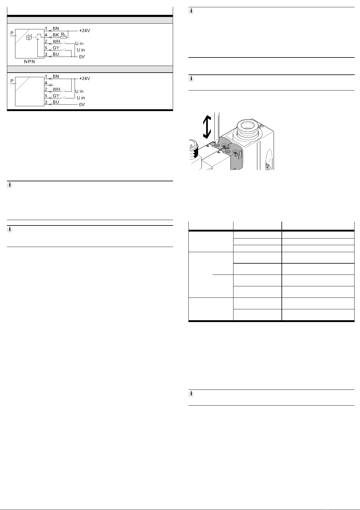
Fig. 2 Switching characteristics of switching inputs
Code Switching output Switching inputs
-1P Switching output
Positive switching
Switching inputs
Positive switching
-1N Switching output
Negative switching
Switching inputs
Negative switching
Tab. 4 Switching output and switching input variants
6.2 Switching point and hysteresis
Threshold value comparator
NO (normally open contact)
Tab. 5 Settings for switching points SP, hysteresis Hy and functional reserve FR
The switching point is determined from the teach pressure and the functional
reserve. A functional reserve (35% of the teach pressure) is deducted from the
teach pressure (SP = TP – 0.35*TP). For example,with a teach pressure of
–0.5bar, a switching point of –0.33bar is set. The hysteresis has a fixed value.
7 Assembly
An unfavourable mounting position can impair the function of the product.
• Install the vacuum generator so condensation from the compressed air lines
cannot accumulate in the device.
• Install the vacuum generator so that it cannot be heated above the maximum
permissible operating temperature (plan for possible convection).
• Install the vacuum generator so that the exhaust can flow without hindrance.
Direct mounting
Fig. 3 Direct mounting on the side
Variant Screws Tightening torque
OVEM-...-05/-07/-10-...-B M5 max. 2.5Nm
OVEM-...-14/-20-...-B M4 max. 2.5Nm
OVEM-...-20/-30-...-C M6 max. 2.5Nm
Tab. 6 Size and tightening torque of the screws for direct mounting on the side