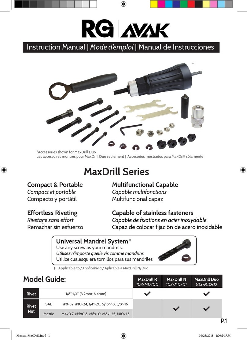
Festo DFST-G2 Series Parts list manual

8104050
DFST-50 ... 80-G2
Stopper cylinder
8104050
2019-02
[8104052]
Instructions| Operat-
ing

Translation of the original instructions
2 Festo — DFST-50 ... 80-G2 — 2019-02

3Festo — DFST-50 ... 80-G2 — 2019-02
1 Further applicable documents..................................................................................... 4
2 Safety........................................................................................................................... 4
2.1 Safety instructions........................................................................................................ 4
2.2 Intended use................................................................................................................ 4
2.3 Foreseeable misuse...................................................................................................... 4
2.4 Training of qualified personnel..................................................................................... 4
3 Further information..................................................................................................... 5
4 Service..........................................................................................................................5
5 Product overview......................................................................................................... 5
5.1 Function....................................................................................................................... 5
5.2 Design........................................................................................................................... 6
6 Mounting..................................................................................................................... 7
6.1 Preparation................................................................................................................... 7
6.2 Mounting...................................................................................................................... 9
6.3 Mounting accessories................................................................................................... 9
7 Pneumatic installation................................................................................................ 10
8 Commissioning............................................................................................................ 11
9 Maintenance................................................................................................................ 12
9.1 Cleaning....................................................................................................................... 12
9.2 Lubrication................................................................................................................... 13
9.3 Fault clearance............................................................................................................. 13
9.4 Repair............................................................................................................................14
10 Modification................................................................................................................ 14
11 Disposal........................................................................................................................14
12 Technical data............................................................................................................. 15
Table of contents
1 Further applicable documents
All available documents for the product èwww.festo.com/pk.
2 Safety
2.1 Safety instructions
– Take into consideration the ambient conditions at the location of use.
– Only use the product in original status without unauthorised modifications.
– Observe labelling on the product.
– Store the product in a cool, dry, UV-protected and corrosion-protected environment. Ensure that
storage times are kept to a minimum.
– Prior to mounting, installation and maintenance work: Switch off compressed air supply and
secure it from being switched back on.
– Observe tightening torques. Unless otherwise specified, the tolerance is±20%.
2.2 Intended use
The stopper cylinder DFST is designed for use as a retractable fixed stop in order to reach defined
holding positions with transported material (e.g. on mounting or sorting systems). The DFST sorts the
stationary transported material in buffer zones.
Fig. 1 Stopping transported material
2.3 Foreseeable misuse
With DFST-...-L: the toggle lever must not be overrun in the stop direction by the transported material
when the lever locking mechanism is active. Otherwise the transported material will damage the lock-
ing mechanism.
2.4 Training of qualified personnel
Installation, commissioning, maintenance and disassembly should only be conducted by qualified per-
sonnel.
The skilled personnel must be familiar with the installation of pneumatic control systems.
Further applicable documents
Festo — DFST-50 ... 80-G2 — 2019-024

3 Further information
– Accessories èwww.festo.com/catalogue.
– Spare parts èwww.festo.com/spareparts.
4 Service
Contact your regional Festo contact person if you have technical questions èwww.festo.com.
5 Product overview
5.1 Function
The stopper cylinder DFST is a double-acting cylinder. The piston rod is extended with the toggle lever
mechanism by pressurising the supply port 1. The toggle lever gently stops the incoming transpor-
ted material with the integrated shock absorber. The piston rod is retracted by pressurising the supply
port 2. The stopper cylinder with spring return (not applicable for DFST-...-D/DL) can also be set to
single-acting. This is done by screwing a silencer into the supply port 1 on the bottom. This makes
sense if reduced extension velocities are sufficient.
With the stopper cylinder DFST-..-L with factory-installed lever locking mechanism, the toggle lever
locks into its end position. The attached toggle lever function kit must be converted in order to use the
function of the lever deactivating mechanism è 10 Modification.
Further information
5Festo — DFST-50 ... 80-G2 — 2019-02

5.2 Design
1Supply port (extending, 2x)
2Supply port (retracting, 2x)
3Piston rod
4Drilled hole for pin for lever locking mechan-
ism/lever deactivating mechanism (2x)
5Roller toggle lever
6Stop roller (2x)
7Thread for inductive proximity sensor (2x)
8Knurled nut for setting the cushioning
9Guide rod for protection against rotation
10 Toggle lever function kit (optional)
11 Through-hole for mounting (4x)
12 Slot for proximity sensor (6x)
Fig. 2 Product design stopper cylinder DFST-...-G2
Product overview
6 Festo — DFST-50 ... 80-G2 — 2019-02

6 Mounting
6.1 Preparation
Fig. 3 Maintain required distances
• Leave sufficient space for the pneumatic connections and for replacing the shock absorber.
Fig. 4 Alignment of transported material
• Observe the following points:
– the transported material impacts both rollers of the toggle lever
– the direction of transport of the transported material is exactly perpendicular to the roller
toggle lever.
– with lever deactivating mechanism installed, the toggle lever can lock if the transported
material is stationary above the stopper cylinder when the piston rod is extended.
Mounting
7Festo — DFST-50 ... 80-G2 — 2019-02

9Guide rod
Fig. 5 Changing stopper head
• The roller toggle lever 9can be rotated 90° to each of 4positions by the offset of the guide rod.
Lock guide rod with thread-locking compound when screwing it into the new position.
Fig. 6 Mounting distances
• Observe distances X1, X2 and X3. The distances refer to the bottom of the flange as the mounting
level of the stopper cylinder with the piston rod extended.
Size 50 63 80
X1 (maximum distance from the bottom of the
pallet)
[mm] 112.1 129.2 152
X2 (toggle lever pressed) [mm] 117.8 134 159
X3 (minimum distance from the bottom of the
pallet)
[mm] 106.8 123.5 143.8
Tab. 1 Mounting clearances
Mounting
8 Festo — DFST-50 ... 80-G2 — 2019-02

6.2 Mounting
Fig. 7 Direct mounting
• Fasten the stopper cylinder with 4 screws.
Size 50 63 80
Screw M8 M10 M12
Tab. 2 Screw sizes
6.3 Mounting accessories
Fig. 8 Mounting positions for accessories
• Mount accessories according to the assembly instructions:
– Use proximity sensors in the thread 8or in the slot aB
– Toggle lever function kit aJ on the stopper cylinder.
Mounting
9Festo — DFST-50 ... 80-G2 — 2019-02

7 Pneumatic installation
• Select one of the two alternative connections:
AConnection on flange BConnection from below
Fig. 9 Alternative pneumatic ports
• Select one of the two actuation types (single-acting/double-acting):
2Retracting connection 1Extending connection
Fig. 10 Double-acting actuation
2Retracting connection SSilencer
Fig. 11 Single-acting actuation
1. When used as a single-acting cylinder: screw a silencer into the supply port on the bottom
(èwww.festo.com/catalogue).
2. Connect hoses to supply ports.
If necessary, convert and seal threaded pins in the alternative connections.
Pneumatic installation
10 Festo — DFST-50 ... 80-G2 — 2019-02

8 Commissioning
WARNING!
Risk of injury due to unexpected movement of components.
• Protect the positioning range from unwanted intervention.
• Keep foreign objects out of the positioning range.
1. Pressurise the system slowly.
2. Start test run:
Double-acting insert Single-acting insert Reaction
Pressurise1 supply port. Exhaust2 supply port. The piston rod extends.
Start stopper cylinder with transported material. The moving transported
material is stopped and
presses the toggle lever to the
rear end position (with the
DFST-...-L variant this locks the
toggle lever).
Pressurise2 supply port and
exhaust supply1 port.
Pressurise2 supply port. The piston rod retracts. The
toggle lever lock is released.
The transported materials is
moved on.
Pressurise1 supply port and
exhaust supply2 port.
Exhaust2 supply port. Piston rod extends. The stop-
per cylinder can stop the next
batch of transported material.
Tab. 3 Commissioning steps
3. Finish test run after completing all settings.
Automatic unlocking of the lever locking/deactivation mechanism with DFST-...-L (accessories)
Fig. 12 Unlocking/activating toggle lever
• Pressurise2 supply port.
ÄWhen the piston rod is retracted, it presses the lever locking/deactivation mechanism on the
screw and releases the toggle lever.
Commissioning
11Festo — DFST-50 ... 80-G2 — 2019-02

Cushioning setting
Fig. 13 Adjust shock absorber
1. Loosen lock nut [C].
2. Turn knurled nut until the desired cushioning is reached.
ÄWhen the setting is correct, the transported material presses the toggle lever quickly and
stops. The cushioning is too hard if the transported material springs back immediately or
requires a long time to press the toggle lever down completely. The cushioning is too soft if
the toggle lever hits the end position hard without any visible damping.
The setting range is approx. 270° and has an upper and a lower stop:
– Turn knurled nut 7 anticlockwise in the direction "Max" mark: cushioning becomes
harder.
– Turn knurled nut 7 clockwise to the "0" mark: cushioning becomes softer
Mark positions of the knurled nuts. This simplifies adjustment of the cushioning when repla-
cing a shock absorber.
3. Tighten lock nut [C]. Tightening torque: 2 Nm
9 Maintenance
9.1 Cleaning
Clean the outside of the product with a soft cloth. Do not use aggressive cleaning agents.
Maintenance
12 Festo — DFST-50 ... 80-G2 — 2019-02

9.2 Lubrication
• After every cleaning grease the following components with LUB-KC1
èwww.festo.com/spareparts:
3Piston rod
9Guide rod
10 Lever locking/deactivation mechanism
13 Thrust bolts
14 Bolt of the toggle lever
15 Bolt of the stop roller
Fig. 14 Lubrication points
• With DFST-...-L with lever locking/deactivation mechanism: also grease all bearing points of the
moving parts.
9.3 Fault clearance
Malfunction Possible cause Remedy
Wear on one side of the
guide rod
Transported material
impacts diagonally on
the toggle lever
Align stopper cylinder in the direction of trans-
port, transported material must meet the toggle
lever vertically è 6.1 Preparation
Cushioning incorrectly
set
Correct cushioning è 8 Commissioning
Conveyor speed too
high
Reduce velocity
Hard impact on the
toggle lever
Shock absorber faulty Replace shock absorber
(èspare parts catalogue, www.festo.com)
Tubing connection error Check blanking plug
Check tubing connection
Piston rod in initial pos-
ition despite pressur-
isation Reduced flow rate
through elbow connect-
ors
Avoid elbow connectors
Cushioning incorrectly
set
Correct cushioning è 8 CommissioningToggle lever does not
reach end position
Transported material
load (push-through
force) too low
– Increase load
– Increase coefficient of friction between con-
veyor and material
– Increase slope of conveyor
Tab. 4 Fault clearance
Maintenance
13Festo — DFST-50 ... 80-G2 — 2019-02

9.4 Repair
WARNING!
Risk of injury caused by ejected components.
Springs under tension and compressed air eject the piston cap outwards when demounting the retain-
ing ring.
• Never release the retaining ring on the bottom of the product.
• Open the product only by unscrewing the fitting between the flange cover and cylinder barrel.
SRetaining ring
Fig. 15 Do not release retaining ring
Send the product to the Festo repair service for repair.
Replace shock absorber
1. Marking the setting of the old shock absorber on the stopper cylinder.
2. Replace shock absorber.
3. Turn knurled nut of the new shock absorber clockwise to the stop (zero setting).
4. Mark zero setting on the knurled nut.
5. Turn mark to previous setting.
10 Modification
With DFST-...-L: modification for deactivation of toggle lever èattached assembly instructions.
11 Disposal
Dispose of the product and packaging at the end of its useful life through environmentally friendly
recycling in accordance with applicable regulations.
Modification
14 Festo — DFST-50 ... 80-G2 — 2019-02

12 Technical data
Size 50 63 80
Design Piston rod with toggle lever
Mode of operation D– double-acting with spring (extending)
L– with lever locking/deactivation mechanism
Mounting position Vertical
Operating medium Compressed air to ISO 8573-1:2010 [7:–:–]
Operating pressure
range
[bar] 2…10
Pneumatic connection G1/8
Max. permissible
weight of the load to be
stopped
[kg] 400 (at v =
10m/min)
480 (at v =
13m/min)
800 (at v =
15m/min)
Reset force
– of the toggle lever
(max.)
[N] 11 23 36
– Reset spring of the
piston rod (min.)
[N] 35 55 62
Cushioning
– Cylinder elastic cushioning rings/plates, at both ends
– Toggle lever Adjustable shock absorber
Ambient temperature [°C] +5…+60 °C
Materials
– Cover, housing Aluminium
– Piston rod High-alloy stainless steel
– Attachments Cast steel, nickel-plated
– Screws Steel
– Rollers POM, steel (with DFST-...-S)
– Seals NBR
Weight [g] 1930 3410 6340
Tab. 5
Technical data
15Festo — DFST-50 ... 80-G2 — 2019-02

Reproduction, distribution or sale of this document or communic-
ation of its contents to others without express authorization is
prohibited. Offenders will be liable for damages. All rights
reserved in the event that a patent, utility model or design patent
is registered.
Copyright:
Festo SE & Co. KG
Ruiter Straße 82
73734 Esslingen
Germany
+49 711 347-0
+49 711 347-2144
Fax:
www.festo.com
Internet:
Phone:
e-mail:
This manual suits for next models
3
Table of contents