FFC BOX SCRAPER Product manual

800-456-7100 I www.paladinlcg.com 503 Gay Street, Delhi, IA 52223, United States of America
SERIALNUMBER:___________________ ManualNumber:MR15554
PartNumber:13884&13888
MODELNUMBER:___________________ Rev.2
OPERATOR’SANDPARTS
MANUAL
BOXSCRAPER
2/19/09
13888Shown


2/19/09 MR15554 1
TABLE OF CONTENTS
INTRODUCTION .................................................................................................... 2
GENERAL INFORMATION ..................................................................................... 2
SERIAL NUMBER ................................................................................................... 2
OWNER AND OPERATOR SAFETY INFORMATION
SAFETY STATEMENTS ............................................................................... 3
SAFETY PRECAUTIONS ............................................................................. 4-5
SAFETY SIGNS ............................................................................................ 6-7
SPECIFICATIONS .................................................................................................... 8-9
MOUNTING ............................................................................................................. 10
HYDRAULIC CONNECTION ................................................................................... 11
SETUP ..................................................................................................................... 12
OPERATION ............................................................................................................ 13
MAINTENANCE ....................................................................................................... 14-15
SERVICE ................................................................................................................. 16-17
PARTS ILLUSTRATION ......................................................................................... 18
PARTS LIST ............................................................................................................ 19
WARRANTY .............................................................................................................. i

2/19/09
MR15554
2
INTRODUCTION
Congratulations on your purchase of a new FFC Box Scraper. This product has been
designed and built to excavate, backfill, grade, and scarify soil materials. You or any other
person who will be assembling, operating, maintaining, or working with this product are
required to read and completely understand the information and instructions contained in this
manual. If anyone does not fully understand every part of this manual, please obtain further
assistance by contacting the dealer from which this product was purchased or by contacting
FFC at the telephone number or address listed on the cover of this manual. Keep this
manual available for reference whenever this product is being handled or used. Provide this
manual to any new owners and/or operators.
This manual covers model(s): 13884 and 13888. The difference between the models is the
width and the end plates on the product, details of which are covered on the parts list and
specifications page(s).
GENERAL INFORMATION
The purpose of this manual is to assist in assembling, mounting, operating, and maintaining
your Box Scraper. Read this manual carefully to obtain valuable information and instructions
that will help you achieve years of safe and dependable service.
The illustrations and data used in this manual were current at the time of printing, but due
to possible engineering and/or production changes, this product may vary slightly in detail.
FFC reserves the right to redesign and/or change components as may be necessary without
notification to anyone.
Throughout this manual, references may be made to:
Prime Mover The engine-driven machine to which this product must be attached.
Right, Left, Front,
Rear Directions that are determined in relation to the operator of the equip-
ment when seated in the normal operation position.
IMPORTANT Precautions that must be followed to prevent substandard performance.
SERIAL NUMBER LOCATION
Always refer to the model and serial number when ordering parts or requesting information
from your dealer. The serial number plate for this product is located on the top left surface of
the loader attachment plate of your Box Scraper.
Reference Information
Model Number Loader Make
Serial Number Loader Model
Date Purchased Loader Serial Number

2/19/09 MR15554 3
SAFETY STATEMENTS
THIS SYMBOL BY ITSELF OR WITH A WARNING WORD THROUGHOUT THIS
MANUAL IS USED TO CALL YOUR ATTENTION TO INSTRUCTIONS INVOLVING
YOUR PERSONAL SAFETY OR THE SAFETY OF OTHERS. FAILURE TO FOLLOW
THESE INSTRUCTIONS CAN RESULT IN INJURY OR DEATH.
DANGER THIS SIGNAL WORD IS USED WHERE SERIOUS INJURY OR DEATH WILL
RESULT IF THE INSTRUCTIONS ARE NOT FOLLOWED PROPERLY.
WARNING THIS SIGNAL WORD IS USED WHERE SERIOUS INJURY OR DEATH
COULD RESULT IF THE INSTRUCTIONS ARE NOT FOLLOWED PROPERLY.
CAUTION THIS SIGNAL WORD IS USED WHERE MINOR INJURY COULD RESULT IF
THE INSTRUCTIONS ARE NOT FOLLOWED PROPERLY.
NOTICE NOTICE INDICATES A PROPERTY DAMAGE MESSAGE.
GENERAL SAFETY PRECAUTIONS
WARNING! READ MANUAL PRIOR TO INSTALLATION
Improper installation, operation, or maintenance of this equipment could result in
serious injury or death. Operators and maintenance personnel should read this manual,
as well as all manuals related to this equipment and the prime mover thoroughly
before beginning installation, operation, or maintenance. FOLLOW ALL SAFETY
INSTRUCTIONS IN THIS MANUAL AND THE PRIME MOVER'S MANUAL(S).
READ AND UNDERSTAND ALL SAFETY STATEMENTS
Read all safety decals and safety statements in all manuals prior to operating or
working on this equipment. Know and obey all OSHA regulations, local laws,
and other professional guidelines for your operation. Know and follow good work
practices when assembling, maintaining, repairing, mounting, removing, or
operating this equipment.
KNOW YOUR EQUIPMENT
Know your equipment’s capabilities, dimensions and operations before operating.
Visually inspect your equipment before you start, and never operate equipment that
is not in proper working order with all safety devices intact. Check all hardware to
ensure it is tight. Make certain that all locking pins, latches, and connection devices
are properly installed and secured. Remove and replace any damaged, fatigued, or
excessively worn parts. Make certain all safety decals are in place and are legible.
Keep decals clean, and replace them if they become worn and hard to read.

2/19/09
MR15554
4
GENERAL SAFETY PRECAUTIONS
WARNING! PROTECT AGAINST FLYING DEBRIS
Always wear proper safety glasses, goggles or a face shield when driving pins in or
out, or when any operation causes dust, flying debris, or any other hazardous material.
WARNING! LOWER OR SUPPORT RAISED EQUIPMENT
Do not work under raised booms without supporting them. Do not use support
material made of concrete blocks, logs, buckets, barrels or any other material that
could suddenly collapse or shift positions. Make sure support material is solid, not
decayed, warped, twisted, or tapered. Lower booms to ground level or onto blocks.
Lower booms and attachments to the ground before leaving the cab or operator’s
station.
WARNING! USE CARE WITH HYDRAULIC FLUID PRESSURE
Hydraulic fluid under pressure can penetrate the skin and cause serious injury or
death. Hydraulic leaks under pressure may not be visible. Before connecting or
disconnecting hydraulic hoses, read your prime movers operator’s manual for detailed
instructions on connecting and disconnecting hydraulic hoses or fittings.
• Keep unprotected body parts, such as face, eyes, and arms as far away as
possible from a suspected leak. Flesh injected with hydraulic fluid may develop
gangrene or other permanent disabilities.
• If injured by injected fluid, see a doctor at once. If your doctor is not familiar with
this type of injury, ask him to research immediately to determine proper treatment.
• Wear safety glasses, protective clothing, and use a sound piece of cardboard or
wood when searching for hydraulic leaks. DO NOT USE YOUR HANDS!
SEE ILLUSTRATION.
CARDBOARD
HYDRAULIC HOSE
OR FITTING
MAGNIFYING GLASS

2/19/09 MR15554 5
GENERAL SAFETY PRECAUTIONS
WARNING! DO NOT MODIFY MACHINE OR ATTACHMENTS
Modifications may weaken the integrity of the attachment and may impair the function,
safety, life, and performance of the attachment. When making repairs, use only the
manufacturer’s genuine parts, following authorized instructions. Other parts may be
substandard in fit and quality. Never modify any ROPS (Roll Over Protection Structure)
or FOPS (Falling Object Protective Structure) equipment or device. Any modifications
must be authorized in writing by the manufacturer.
WARNING! SAFELY MAINTAIN AND REPAIR EQUIPMENT
• Do not wear loose clothing, or any accessories that can catch in moving parts.
If you have long hair, cover or secure it so that it does not become entangled in
the equipment.
• Work on a level surface in a well-lit area.
• Use properly grounded electrical outlets and tools.
• Use the correct tool for the job at hand. Make sure they are in good condition
for the task required.
• Wear the protective equipment specified by the tool manufacturer.
WARNING! SAFELY OPERATE EQUIPMENT
Do not operate equipment until you are completely trained by a qualified operator in
how to use the controls, know its capabilities, dimensions, and all safety requirements.
See your machine's manual for these instructions.
• Keep all step plates, grab bars, pedals, and controls free of dirt, grease,
debris, and oil.
• Never allow anyone to be around the equipment when it is operating.
• Do not allow riders on the attachment or the prime mover.
• Do not operate the equipment from anywhere other than the correct operators
position.
• Never leave equipment unattended with the engine running or with this
attachment in a raised position.
• Do not alter or remove any safety feature from the prime mover or this attachment.
• Know your work site safety rules as well as traffic rules and flow. When in
doubt on any safety issue, contact your supervisor or safety coordinator for an
explanation.
WARNING! KNOW WHERE UTILITIES ARE
Observe overhead electrical and other utility lines. Be sure equipment will clear them.
When digging, call your local utilities for location of buried utility lines, gas, water, and
sewer, as well as any other hazard you may encounter.

2/19/09
MR15554
6
SAFETY SIGN LOCATIONS
The diagram on this page shows the location of the decals used on the FFC Box Scraper. The
decals are identified by their part numbers, with reductions of the actual decals located on the following
page. Use this information to order replacements for lost or damaged decals. Be sure to read all decals
before operating the attachment. They contain information you need to know for both safety and product
longevity.
INSTRUCTIONS
• Keep all safety signs clean and legible.
• Replace all missing, illegible, or damaged safety signs.
• Replacement parts for parts with safety signs attached must also have safety signs attached.
• Safety signs are available, free of charge, from your dealer or from FFC.
PLACEMENT OR REPLACEMENT OF SAFETY SIGNS
1. Clean the area of application with non-flammable solvent, and then wash the same area with soap
and water.
2. Allow the surface to fully dry.
3. Remove the backing from the safety sign, exposing the adhesive surface.
4. Apply the safety sign to the position shown in the diagram above and smooth out any bubbles.
50-0737
50-0737
50-0724
40150
RDL3155
RDL3155
Serial # Tag

2/19/09 MR15554 7
SAFETY SIGNS
PART # 40150
WARNING! READ MANUAL
PART # 50-0724
WARNING! HIGH PRESSURE FLUID
PART # 50-0737
WARNING! PINCH POINT HAZARD
PART # RDL3155
RED REFLECTIVE TAPE

2/19/09
MR15554
8
PRIME MOVER SPECIFICATIONS
IMPORTANT Exceeding any of the maximum recommended prime mover specifications
CANresult in damage to this product and
WILL void all FFC warranties.
DESCRIPTION SPECIFICATIONS
Weight of Prime Mover without Box Scraper 20,000 lbs. maximum
Category of Prime Mover's 3-Point Hitch Category II only
Hydraulic Pressure Output 4,000 psi maximum
Rear Ballast As required to maintain full prime mover stability.
(Note the Shipping Weight on the specifications page, then see
the operator’s manual(s) for your prime mover, 3-point hitch,
and quick hitch for ballasting needs.)
BOX SCRAPER SPECIFICATIONS
Model
Number Overall
Width Overall
Height* Overall
Depth Cutting
Width Excavation
Capacity Shipping
Weight
13884 85" 39.63" 45.50" 84" 38.4 cu. ft. 1565 lbs.
13888 89" 39.63" 45.50" 88"
All replacement hydraulics must have a minimum rated working pressure of 4,000 psi.

2/19/09 MR15554 9
BOLT TORQUE
BOLT TORQUE SPECIFICATIONS
GENERAL TORQUE SPECIFICATION TABLES
8VHWKHIROORZLQJFKDUWVZKHQGHWHUPLQLQJEROWWRUTXHVSHFL¿FDWLRQVZKHQVSHFLDOWRUTXHVDUHQRW
given. Always use grade 5 or better when replacing bolts.
SAE BOLT TORQUE SPECIFICATIONS
NOTE: The following torque values are for use with extreme pressure lubricants, plating or hard washer
applications Increase torque 15% when using hardware that is unplated and either dry or lubricated with
engine oil.
Bolt Size
SAE GRADE 5 TORQUE SAE GRADE 8 TORQUE
Pounds Feet Newton-Meters Pounds Feet Newton-Meters
%ROWKHDGLGHQWL¿FDWLRQPDUNVDVSHUJUDGH
NOTE: Manufacturing Marks Will Vary
Inches Millimeters UNC UNF UNC UNF UNC UNF UNC UNF
1/4 6.35 8 9 11 12 10 13 14 18
5/16 7.94 14 19 19 23 20 25 27 34
3/8 9.53 30 36 41 49 38 46 52 62
7/16 11.11 46 54 62 73 60 71 81 96
1/2 12.70 68 82 92 111 94 112 127 152
9/16 14.29 94 112 127 152 136 163 184 221
5/8 15.88 128 153 174 207 187 224 254 304
3/4 19.05 230 275 312 373 323 395 438 536
7/8 22.23 340 408 461 553 510 612 691 830
1 25.40 493 592 668 803 765 918 1037 1245
1-1/8 25.58 680 748 922 1014 1088 1224 1475 1660
1-1/4 31.75 952 1054 1291 1429 1547 1700 2097 2305
1-3/8 34.93 1241 1428 1683 1936 2023 2312 2743 3135
1-1/2 38.10 1649 1870 2236 2535 2686 3026 3642 4103
METRIC BOLT TORQUE SPECIFICATIONS
NOTE: The following torque values are for use with metric hard-
ware that is unplated and either dry or lubricated with engine oil.
Reduce torque 15% when using hardware that has extreme
pressure lubricants, plating or hard washer applications.
Size of Bolt Grade No. Pitch (mm) Pounds Feet Newton-Meters Pitch (mm) Pounds Feet Newton-Meters
5.6 3.6-5.8 4.9-7.9 - -
M6 8.8 1.0 5.8-.4 7.9-12.7 - - -
10.9 7.2-10 9.8-13.6 - -
5.6 7.2-14 9.8-19 12-17 16.3-23
M8 8.8 1.25 17-22 23-29.8 1.0 19-27 25.7-36.6
10.9 20-26 27.1-35.2 22-31 29.8-42
5.6 20-25 27.1-33.9 20-29 27.1-39.3
M10 8.8 1.5 34-40 46.1-54.2 1.25 35-47 47.4-63.7
10.9 38-46 51.5-62.3 40-52 54.2-70.5
5.6 28-34 37.9-46.1 31-41 42-55.6
M12 8.8 1.75 51-59 69.1-79.9 1.25 56-68 75.9-92.1
10.9 57-66 77.2-89.4 62-75 84-101.6
5.6 49-56 66.4-75.9 52-64 70.5-86.7
M14 8.8 2.0 81-93 109.8-126 1.5 90-106 122-143.6
10.9 96-109 130.1-147.7 107-124 145-168
5.6 67-77 90.8-104.3 69-83 93.5-112.5
M16 8.8 2.0 116-130 157.2-176.2 1.5 120-138 162.6-187
10.9 129-145 174.8-196.5 140-158 189.7-214.1
5.6 88-100 119.2-136 100-117 136-158.5
M18 8.8 2.0 150-168 203.3-227.6 1.5 177-199 239.8-269.6
10.9 175-194 237.1-262.9 202-231 273.7-313
5.6 108-130 146.3-176.2 132-150 178.9-203.3
M20 8.8 2.5 186-205 252-277.8 1.5 206-242 279.1-327.9
10.9 213-249 288.6-337.4 246-289 333.3-391.6
%ROWKHDGLGHQWL¿FDWLRQPDUNVDVSHUJUDGH

2/19/09
MR15554
10
BOX SCRAPER MOUNTING
WARNING! READ MANUAL PRIOR TO INSTALLATION
Improper installation, operation, or maintenance of this equipment could result in
serious injury or death. Operators and maintenance personnel should read this
manual, as well as all manuals related to this equipment and the prime mover
thoroughly before beginning installation, operation, or maintenance. FOLLOW ALL
SAFETY INSTRUCTIONS IN THIS MANUAL AND THE PRIME MOVER'S
MANUAL(S).
1. Place this product on a firm, level surface that is large enough to safely accommodate this
product, your prime mover and all workers involved in the mounting process.
2. Refer to the operator’s manual(s) for your prime mover, 3-point hitch, and quick hitch and follow
the mounting instructions contained therein.
3. Carefully raise the 3-point hitch to check clearances and to verify that all mounting procedures
have been successfully completed.
4. IMPORTANT Lubricate all grease fittings before connecting this product to your prime
mover's hydraulic system. Refer to BOX SCRAPER MAINTENANCE and
follow the instructions

2/19/09 MR15554 11
BOX SCRAPER HYDRAULIC CONNECTION
READ AND UNDERSTAND ALL SAFETY STATEMENTS
Read all safety decals and safety statements in all manuals before beginning any Snow
Blower hydraulic connection. Know and obey all OSHA regulations, local laws, and other
professional guidelines for your operation. Know and follow good work practices when
assembling, maintaining, repairing, mounting, removing, or operating this equipment.
1. Remove all the protective plastic caps from the hose ends.
2. Make the connection to your prime mover using the appropriate method below for your prime mover:
• If your prime mover has male or female threads for connecting the hydraulic hoses to the auxiliary
hydraulic lines, make certain that the threads, as well as the inside of the fittings and hoses, are
clean, then secure the hoses to the fittings using the torque specified in your prime mover’s
operator’s manual.
• If your prime mover has quick-couplers for connecting the hydraulic hoses to the auxiliary hydraulic
lines, you may need to purchase the proper quick-coupler fittings that you must install on the free
ends of the two hoses. In most cases, the owner’s manual for your prime mover will describe the
exact type of fitting that is needed for your hydraulic coupling system, but in no case should any
fitting have an allowable operating pressure of less than 4,000 psi. Once all the quick-coupler
fittings are properly installed, then the hoses can be coupled to the prime mover’s hydraulic valve
body or auxiliary hydraulic lines as per the instructions found in your prime mover’s operator’s
manual.
3. Carefully raise the 3-point hitch to check hose clearances and to check for any interference. Operate
the hydraulic cylinder(s) on this product to make the same checks.
4. Cycle the hydraulic cylinder(s) on this product several times from fully retracted to fully extended
until all air has been completely removed from the cylinder(s).
WARNING! Do not lock the auxiliary hydraulics of your prime mover in the "ON" position.
Failure to obey this warning could result in death or serious injury.
NOTICE: When shipped, the hydraulic cylinder(s) on this product contained air or an air-fluid mixture.
There are orifices beneath the port(s) in the hydraulic cylinder barrel(s) that will restrict the
exit of that air. Failure to remove all the air from the hydraulic cylinder(s) can cause
uneven, jerky cylinder movement when the hydraulic controls are being operated and
unwanted cylinder movement when the controls are not being operated.

2/19/09
MR15554
12
BOX SCRAPER SETUP
READ AND UNDERSTAND ALL SAFETY STATEMENTS
Read all safety decals and safety statements in all manuals before beginning any Snow
Blower setup. Know and obey all OSHA regulations, local laws, and other professional
guidelines for your operation. Know and follow good work practices when assembling,
maintaining, repairing, mounting, removing, or operating this equipment.
EXCAVATING, GRADING, AND BACKFILLING
Park your prime mover on a level surface with this product properly attached.
Place your prime mover's transmission in "Park" and engage the parking brake.
Lower this product onto the level surface.
Make sure that the hydraulic cylinder is fully extended so that the ripper shanks are in the fully raised
position.
Shut off your prime mover's engine, remove the starter key, wait for all moving parts to come to a
stop, and relieve all pressure in the hydraulic lines.
Check to see that the cutting edges of this product are parallel to the level surface. If they are not
parallel, make the edges and the level surface parallel by following the instructions for adjustment of
the 3-point hitch as found in the operator's manual(s) for your prime mover and 3-point hitch.
Check to see that the bases of the main frame end plates are parallel to the level surface. If they are
not parallel, make the bases and the level surface parallel by adjusting the 3-point hitch's top link as
described in the operator's manual(s) for the prime mover and 3-point hitch.
SCARIFYING
Perform steps 1 through 6 above.
Check to see that the bases of the main frame end plates are leaning forward approximately 15
degrees relative to the level surface. If this is not the case, adjust the 3-point hitch's top link as
described in the operator's manual(s) for your prime mover and 3-point hitch. Leaning this product
forward 15 degrees will lift the cutting edges up a few inches off the level surface and will result
in the straight upper portion of the ripper shanks being perpendicular (90 degrees) to the ground
surface during operation.
Verify that the ripper shanks are set in the proper slot for performing the desired work. When the
front edges of the main frame end plates are flush with the ground level, then:
• positioning the ripper shanks in the lower slot will produce a 3-3/4" deep cut and
• positioning the ripper shanks in the upper slot will produce a 6-1/4" deep cut.
See RIPPER SHANK ADJUSTMENT AND REPLACEMENT in the Service section of this manual for
instructions on how to reposition the ripper shanks.
IMPORTANT Operating this product with the ripper shanks only partially extended into the ground
CAN result in damage to this product and
WILL void all FFC warranties.
4. Restart your prime mover and raise the 3-point hitch. Completely retract the hydraulic cylinder to
extend the ripper shanks to their lowest and locked position. Failure to lower the ripper shanks
until the locking mechanism engages will result in excessive hydraulic cylinder strain and could
cause permanent hydraulic cylinder damage.
1.
2.
3.
4.
5.
6.
7.
1.
2.
3.

2/19/09 MR15554 13
BOX SCRAPER OPERATION
READ AND UNDERSTAND ALL SAFETY STATEMENTS
Read all safety decals and safety statements in all manuals prior to operating or
working on this equipment. Know and obey all OSHA regulations, local laws,
and other professional guidelines for your operation. Know and follow good work
practices when assembling, maintaining, repairing, mounting, removing, or
operating this equipment.
WARNING! Failure to obey the following procedures could result in death or serious injury.
• Make sure that a qualified individual or firm that specializes in locating
underground utilities has inspected the work area. Do not operate this product
where contact with a utility line of any kind is possible.
• Operate at a very slow ground speed where objects that are not easily moveable
(i.e. stumps, concrete foundations, etc.) may be present.
IMPORTANT Striking objects that are not easily moveable (i.e. stumps, concrete foundations, etc.)
at an excessive ground speed
CAN result in damage to this product and
WILL void all FFC warranties.
IMPORTANT Backing up with any portion of the ripper shanks below the ground surface
CAN result in damage to this product and
WILL void all FFC warranties.
Before beginning any work, have a qualified individual or firm inspect the entire work area for
underground utility lines. The operator should carefully inspect the entire area for stumps, concrete
foundations, large rocks, posts, or any other solid object that would not easily move when struck by
any part of this product. Remember that you Box Scraper is not your bulldozer and is not designed to
remove pavement, uproot trees, etc.
When excavating, grading or back filling, the performance of this product can be fine-tuned by
adjusting the length of the upper arm of your prime mover's 3-point hitch to increase or decrease
digging capabilities. Changes can also be make by varying your prime mover's speed and by
changing control settings for your prime mover's 3-point hitch.
When scarifying, the best method for achieving a desired digging depth is to perform several test
passes. With there being so may variable in operators and ground conditions, this is the best way
to select the correct ripper shank depth slot, the correct speed, and the correct 3-point hitch control
settings.

2/19/09
MR15554
14
BOX SCRAPER MAINTENANCE
READ AND UNDERSTAND ALL SAFETY STATEMENTS
Read all safety decals and safety statements in all manuals prior to operating or
working on this equipment. Know and obey all OSHA regulations, local laws,
and other professional guidelines for your operation. Know and follow good work
practices when assembling, maintaining, repairing, mounting, removing, or
operating this equipment.
BEFORE EACH USE
• Make sure that all nuts and bolts are in place and properly tightened.
• Make sure that all other fasteners are in place and are performing their specified function.
• Make sure that all hydraulic fittings are tightened to specifications and that there are no leaks in any
fittings or hoses.
(SEE THE HYDRAULIC CONNECTION SECTION)
• Make sure that all safety signs are in place, are clean, and are legible.
(SEE THE SAFETY SIGN SECTION.)
• Replace any damaged parts and excessively worn parts.
AFTER EVERY 10 HOURS OF USE
• Grease 4 fittings: one on the rear face of the pivot tube of the lift linkage weldment;
three on the hydraulic cylinder cross tubes: one on the rod end, and
two on the barrel end.

2/19/09 MR15554 15
MAINTENANCE
MAINTENANCE RECORD
Use this log to record maintenance performed on the attachment.
Date Maintenance Procedure
Performed Performed
by Comments

2/19/09
MR15554
16
BOX SCRAPER SERVICE
READ AND UNDERSTAND ALL SAFETY STATEMENTS
Read all safety decals and safety statements in all manuals prior to operating or
working on this equipment. Know and obey all OSHA regulations, local laws,
and other professional guidelines for your operation. Know and follow good work
practices when assembling, maintaining, repairing, mounting, removing, or
operating this equipment.
RIPPER SHANK ADJUSTMENT, RE-POINTING, AND REPLACEMENT
1. Park your prime mover on a level surface with this product properly attached.
2. Place your prime mover’s transmission in “Park” and engage the parking brake.
3. Lower this product onto the ground with the ripper shanks fully raised.
4. Shut off your prime mover’s engine, remove the starter key, wait for all moving parts to come
to a stop.
5. Lock the scarifier tube in the fully raised position. While standing behind the center of the rear
cutting edge, slide the lockout links to the top of the slot in the mast of the main frame. Remove
the hairpin cotter pin and the clevis pin from the lockout links. Place one lockout link on each
side of the tab on the scarifier tube and secure the lockout links to the tab with the clevis pin and
the hairpin cotter pin.
6. While still standing behind the rear cutting edge, reach forward across the scarifier tube and
remove the rue ring cotter pin, the clevis pin, and the shank block that secures the ripper shank.
7. With one hand, grasp the portion of the ripper shank that extends to the front side of the scarifier
tube and lift up while pushing down with the other hand on the opposite end of the ripper shank.
When clear of the ripper shank slot, slide the ripper shank to the other slot or completely out to
the rear of the scarifier tube, whichever is the desired option.
(For ripper shank adjustment or replacement, skip to step 11. To replace the shank point, continue
with step 8.)
8. WARNING! Failure to obey the following procedures could result in death or
serious injury.
• Read and understand the operator's manuals that came with your cutting torch
and compressed gases before starting any work. Never operate a cutting torch
near any flammable objects or fluids.
9. Cut open the existing shank point using a cutting torch. Make sure that the shank is not being
damaged while the shank point is being cut. Remove and properly dispose of the existing shank
point.
10. Slide a new point onto the ripper shank. Make sure that the cutting face of the shank point is
on top of the hooked end of the ripper shank when the ripper shank is held in the normal
scarifying position.
11. Crimp the shank point onto the ripper shank by pressing the sides of the shank point into the
depressions on each side face of the ripper shank tip. Make sure that the deforming force is
applied directly over the ripper shank depressions and that sufficient deformation occurs for the
shank point to be securely attached to the ripper shank.
12. Reinsert the ripper shank into the scarifier tube and seat the ripper shank in the desired slot.
13. Replace the shank block and then the clevis pin. Secure the clevis pin with the rue ring cotter
pin.

2/19/09 MR15554 17
BOX SCRAPER SERVICE (continued)
READ AND UNDERSTAND ALL SAFETY STATEMENTS
Read all safety decals and safety statements in all manuals prior to operating or
working on this equipment. Know and obey all OSHA regulations, local laws,
and other professional guidelines for your operation. Know and follow good work
practices when assembling, maintaining, repairing, mounting, removing, or
operating this equipment.
REPLACEMENT OF CUTTING EDGES
1. Park your prime mover on a level surface with this product properly attached.
2. Place your prime mover’s transmission in “Park” and engage the parking brake.
3. With the ripper shanks fully lowered and locked into position, lower end plates of the main frame
of this product onto pre-placed blocking as specified below:
WARNING! Failure to obey the following procedures could result in death or
serious injury.
• Do not use blocking made of concrete blocks, logs, buckets, barrels or any other
material that could suddenly collapse or ship positions. Do not use wood or steel
blocking that shows any signs of material decay. Do not use blocking that is
warped, twisted, or tapered.
4. Shut off your prime mover’s engine, remove the starter key, wait for all moving parts to come
to a stop, and relieve all pressure in the hydraulic lines.
5. Make sure that this product is completely stable on the blocking. If the blocking appears to
be unstable or is even of questionable stability, restart your prime mover, raise this product off
the blocking, and move away from the blocking. After the blocking has been repositioned in a
more stable fashion, repeat steps 1 through 5 until a completely stable condition exists.
6. TWO WORKERSARE REQUIRED to remove a cutting edge. From the rear of this product,
reach under the rear cutting edge, loosen and remove the center five nuts, then remove the
corresponding bolts.
7. Loosen the remaining two nuts. While the first worker holds up one end of the cutting edge, the
second worker must remove the nut and bolt from that end so that the first worker can lower that
end of the cutting edge to the surface below. Repeat this process for the remaining bolt.
8. The cutting edge can then be turned end for end and be reinstalled or, if both edges are worn
out, the old cutting edge should be properly discarded. Whether reversing the cutting edge or
installing a new one, replacement of all bolts is recommended. Replacement of all locknuts and
any damaged or worn bolts is required.
9. Reverse the removal process in Step 7 and loosely secure the cutting edge with two bolts: one in
each end hole. Install the other five bolts, then gradually and uniformly tighten all the bolts to
100 ft. lbs. + or - 6.0 ft. lbs., drawing the cutting edge into the proper operating position.
10. If necessary, repeat steps 6 through 9 for the second cutting edge.

2/19/09
MR15554
18
BOX SCRAPER PARTS ILLUSTRATION
8
3
41 29 3
329 34
18
24
1
333027
9
26
32
2
26
7
12
25
42
24
31
12 32 36
23
35 429
3
14
2831
20
23
21
19
37
35
11
5
29
3
11
35
40
43
38 13
3144
15
16
39
17
15
6
10
22
This manual suits for next models
2
Table of contents
Other FFC Farm Equipment manuals
Popular Farm Equipment manuals by other brands
Vicon
Vicon EXTRA 690 T Assembly instructions
Bauer
Bauer 58126 Owner's manual & safety instructions

AL-KO
AL-KO BM 660 Translation of the original operating instructions

Kverneland
Kverneland 2316M Technical & service manual

H&S
H&S Top Shot 5215 Operator's manual
AGCO
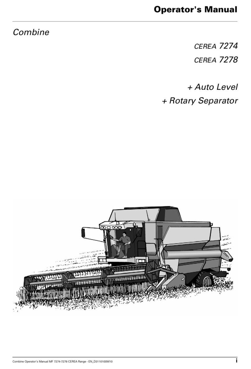
AGCO Combine CEREA 7274 Operator's manual

