FFC LAF1142 Product manual

800-456-7100 I www.paladinlcg.com 503 Gay Street, Delhi, IA 52223, United States of America
SERIALNUMBER:___________________ ManualNumber:MR15533
PartNumber:LAF1142
MODELNUMBER:___________________ Rev.2
OPERATOR’SANDPARTS
MANUAL
LOGGRAPPLE
2-09-09


2/09/09 MR15533 1
TABLE OF CONTENTS
INTRODUCTION ....................................................................................................... 3
GENERAL INFORMATION ....................................................................................... 3
SERIAL NUMBER ..................................................................................................... 3
OWNER AND OPERATOR SAFETY INFORMATION
SAFETY STATEMENTS ................................................................................. 4
SAFETY PRECAUTIONS ............................................................................... 4-7
SAFETY SIGNS ............................................................................................. 8-9
SPECIFICATIONS ..................................................................................................... 10-11
MOUNTING ............................................................................................................... 12
HYDRAULIC CONNECTION .................................................................................... 13
OPERATION ............................................................................................................. 14
MAINTENANCE ........................................................................................................ 15
PARTS ILLUSTRATION ............................................................................................ 16
PARTS LIST .............................................................................................................. 17
WARRANTY .............................................................................................................. i

2/09/09
MR15533
2

2/09/09 MR15533 3
INTRODUCTION
Congratulations on your purchase of a new FFC Log Grapple. This product has been designed and
built to efficiently lift and transport logs, and other loads for which a standard bucket or pallet fork may
not be suited. You or any other person who will be assembling, operating, maintaining, or working
with this product are required to read and completely understand the information and instructions
contained in this manual. If anyone does not fully understand every part of this manual, please obtain
further assistance by contacting the dealer from which this product was purchased or by contacting
FFC at the telephone number or address listed on the cover of this manual. Keep this manual
available for reference whenever this product is being handled or used. Provide this manual to any
new owners and/or operators.
This manual covers model: LAF1142.
GENERAL INFORMATION
The purpose of this manual is to assist in assembling, mounting, operating, and maintaining your
attachment. Read this manual carefully to obtain valuable information and instructions that will help
you achieve years of safe and dependable service.
The illustrations and data used in this manual were current at the time of printing, but due to possible
engineering and/or production changes, this product may vary slightly in detail. FFC reserves the
right to redesign and/or change components as may be necessary without notification to anyone.
Throughout this manual, references may be made to:
Prime Mover The engine-driven machine to which this product must be attached.
Right, Left, Front,
Rear Directions that are determined in relation to the operator of the equipment
when seated in the normal operation position.
IMPORTANT Precautions that must be followed to prevent substandard performance.
SERIAL NUMBER LOCATION
Always refer to the model and serial number when ordering parts or requesting information from your
dealer. See Safety Signs section for the location of the serial number plate for this product.
Reference Information
Model Number Prime Mover Make & Model
Serial Number Loader Model
Date Purchased Loader Serial Number

2/09/09
MR15533
4
SAFETY STATEMENTS
THIS SYMBOL BY ITSELF OR WITH A WARNING WORD THROUGHOUT THIS
MANUAL IS USED TO CALL YOUR ATTENTION TO INSTRUCTIONS INVOLVING
YOUR PERSONAL SAFETY OR THE SAFETY OF OTHERS. FAILURE TO FOLLOW
THESE INSTRUCTIONS CAN RESULT IN INJURY OR DEATH.
DANGER THIS SIGNAL WORD IS USED WHERE SERIOUS INJURY OR DEATH WILL
RESULT IF THE INSTRUCTIONS ARE NOT FOLLOWED PROPERLY.
WARNING THIS SIGNAL WORD IS USED WHERE SERIOUS INJURY OR DEATH
COULD RESULT IF THE INSTRUCTIONS ARE NOT FOLLOWED PROPERLY.
CAUTION THIS SIGNAL WORD IS USED WHERE MINOR INJURY COULD RESULT IF
THE INSTRUCTIONS ARE NOT FOLLOWED PROPERLY.
NOTICE NOTICE INDICATES A PROPERTY DAMAGE MESSAGE.
GENERAL SAFETY PRECAUTIONS
WARNING! READ MANUAL PRIOR TO INSTALLATION
Improper installation, operation, or maintenance of this equipment could result in
serious injury or death. Operators and maintenance personnel should read this manual,
as well as all manuals related to this equipment and the prime mover thoroughly
before beginning installation, operation, or maintenance. FOLLOW ALL SAFETY
INSTRUCTIONS IN THIS MANUAL AND THE PRIME MOVER'S MANUAL(S).
READ AND UNDERSTAND ALL SAFETY STATEMENTS
Read all safety decals and safety statements in all manuals prior to operating or
working on this equipment. Know and obey all OSHA regulations, local laws,
and other professional guidelines for your operation. Know and follow good work
practices when assembling, maintaining, repairing, mounting, removing, or
operating this equipment.
KNOW YOUR EQUIPMENT
Know your equipment’s capabilities, dimensions and operations before operating.
Visually inspect your equipment before you start, and never operate equipment that
is not in proper working order with all safety devices intact. Check all hardware to
ensure it is tight. Make certain that all locking pins, latches, and connection devices
are properly installed and secured. Remove and replace any damaged, fatigued, or
excessively worn parts. Make certain all safety decals are in place and are legible.
Keep decals clean, and replace them if they become worn and hard to read.
2/09/09 MR15533 5
GENERAL SAFETY PRECAUTIONS
WARNING! PROTECT AGAINST FLYING DEBRIS
Always wear proper safety glasses, goggles or a face shield when driving pins in or
out, or when any operation causes dust, flying debris, or any other hazardous material.
WARNING! LOWER OR SUPPORT RAISED EQUIPMENT
Do not work under raised booms without supporting them. Do not use support
material made of concrete blocks, logs, buckets, barrels or any other material that
could suddenly collapse or shift positions. Make sure support material is solid, not
decayed, warped, twisted, or tapered. Lower booms to ground level or onto blocks.
Lower booms and attachments to the ground before leaving the cab or operator’s
station.
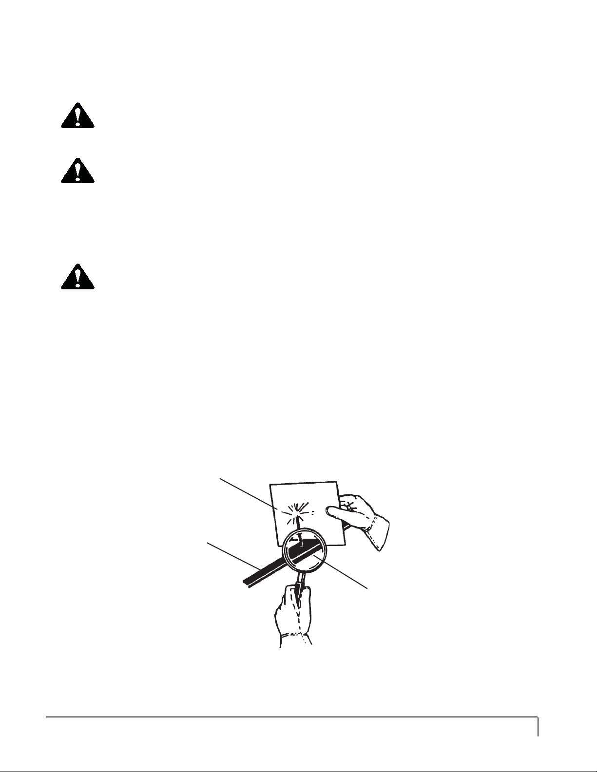
WARNING! USE CARE WITH HYDRAULIC FLUID PRESSURE
Hydraulic fluid under pressure can penetrate the skin and cause serious injury or
death. Hydraulic leaks under pressure may not be visible. Before connecting or
disconnecting hydraulic hoses, read your prime movers operator’s manual for detailed
instructions on connecting and disconnecting hydraulic hoses or fittings.
• Keep unprotected body parts, such as face, eyes, and arms as far away as
possible from a suspected leak. Flesh injected with hydraulic fluid may develop
gangrene or other permanent disabilities.
• If injured by injected fluid, see a doctor at once. If your doctor is not familiar with
this type of injury, ask him to research immediately to determine proper treatment.
• Wear safety glasses, protective clothing, and use a sound piece of cardboard or
wood when searching for hydraulic leaks. DO NOT USE YOUR HANDS!
SEE ILLUSTRATION.
CARDBOARD
HYDRAULIC HOSE
OR FITTING
MAGNIFYING GLASS

2/09/09
MR15533
6
GENERAL SAFETY PRECAUTIONS
WARNING! DO NOT MODIFY MACHINE OR ATTACHMENTS
Modifications may weaken the integrity of the attachment and may impair the function,
safety, life, and performance of the attachment. When making repairs, use only the
manufacturer’s genuine parts, following authorized instructions. Other parts may be
substandard in fit and quality. Never modify any ROPS (Roll Over Protection Structure)
or FOPS (Falling Object Protective Structure) equipment or device. Any modifications
must be authorized in writing by the manufacturer.
WARNING! SAFELY MAINTAIN AND REPAIR EQUIPMENT
• Do not wear loose clothing, or any accessories that can catch in moving parts.
If you have long hair, cover or secure it so that it does not become entangled in
the equipment.
• Work on a level surface in a well-lit area.
• Use properly grounded electrical outlets and tools.
• Use the correct tool for the job at hand. Make sure they are in good condition
for the task required.
• Wear the protective equipment specified by the tool manufacturer.
WARNING! SAFELY OPERATE EQUIPMENT
Do not operate equipment until you are completely trained by a qualified operator in
how to use the controls, know its capabilities, dimensions, and all safety requirements.
See your machine's manual for these instructions.
• Keep all step plates, grab bars, pedals, and controls free of dirt, grease,
debris, and oil.
• Never allow anyone to be around the equipment when it is operating.
• Do not allow riders on the attachment or the prime mover.
• Do not operate the equipment from anywhere other than the correct operators
position.
• Never leave equipment unattended with the engine running or with this attachment
in a raised position.
• Do not alter or remove any safety feature from the prime mover or this attachment.
• Know your work site safety rules as well as traffic rules and flow. When in
doubt on any safety issue, contact your supervisor or safety coordinator for an
explanation.
WARNING! KNOW WHERE UTILITIES ARE
Observe overhead electrical and other utility lines. Be sure equipment will clear them.
When digging, call your local utilities for location of buried utility lines, gas, water, and
sewer, as well as any other hazard you may encounter.

2/09/09 MR15533 7
EQUIPMENT SAFETY PRECAUTIONS
Obey all the safety instructions listed in this section and throughout this manual.
DANGER! DO NOT USE THE LOG GRAPPLE TO LIFT ROUND BALES!
DANGER! GRAPPLE MOVES QUICKLY!
•Do not stand near or place extremities near grapple or between
grapple and implement.

2/09/09
MR15533
8
SAFETY SIGN LOCATIONS
The diagram on this page shows the location of the decals used of the FFC Log Grapple. The
decals are identified by their part numbers, with reductions of the actual decals located on the following
page. Use this information to order replacements for lost or damaged decals. Be sure to read all
decals before operating the attachment. They contain information you nee to know for both safety and
product longevity.
INSTRUCTIONS
• Keep all safety signs clean and legible.
• Replace all missing, illegible, or damaged safety signs.
• Replacement parts for parts with safety signs attached must also have safety signs attached.
• Safety signs are available, free of charge, from your dealer or from FFC.
PLACEMENT OR REPLACEMENT OF SAFETY SIGNS
1. Clean the area of application with non-flammable solvent, and then wash the same
area with soap and water.
2. Allow the surface to fully dry.
3. Remove the backing from the safety sign, exposing the adhesive surface.
4. Apply the safety sign to the position shown in the diagram above and smooth out
any bubbles.
Serial # Tag RDL3139
40150 50-0724
RDL3103
RDL3139
50-0737

2/09/09 MR15533 9
SAFETY SIGNS
PART # 40150
WARNING! READ MANUAL
PART # 50-0724
WARNING! HIGH PRESSURE FLUID
PART # 50-0737
WARNING! PINCH POINT
PART # RDL3125
WARNING! CRUSH HAZARD
PART # RDL3103
WARNING! FALLING LOAD
PART # RDL3139
SAFETY INSTRUCTIONS

2/09/09
MR15533
10
PRIME MOVER/LOADER SPECIFICATIONS
IMPORTANT Exceeding any of the maximum recommended prime mover/loader specifications
CAN result in damage to this product and
WILL void all FFC warranties.
DESCRIPTION SPECIFICATIONS
Lift Capacity of Prime Mover's Loader 6,400 lbs. maximum
Hydraulic Pressure Output 4,000 psi. maximum
Rear Ballast As required to maintain full prime mover stability.
(Note the shipping weight of your model, then see
the operator’s manual(s) for your prime mover and
loader, and quick attach for ballasting needs.)
ATTACHMENT SPECIFICATIONS
Model
Number Overall
Height Grapple
Open Overall
Depth Tine
Length Useable
Tooth Shipping
Weight
LAF1142 48.6" 49.3" 37.85" 29" 28.4" 790 lbs.
All replacement hydraulic hoses and fittings must have a minimum rated working pressure of 4,000 psi.

2/09/09 MR15533 11
BOLT TORQUE
BOLT TORQUE SPECIFICATIONS
GENERAL TORQUE SPECIFICATION TABLES
8VHWKHIROORZLQJFKDUWVZKHQGHWHUPLQLQJEROWWRUTXHVSHFL¿FDWLRQVZKHQVSHFLDOWRUTXHVDUHQRW
given. Always use grade 5 or better when replacing bolts.
SAE BOLT TORQUE SPECIFICATIONS
NOTE: The following torque values are for use with extreme pressure lubricants, plating or hard washer
applications Increase torque 15% when using hardware that is unplated and either dry or lubricated with
engine oil.
Bolt Size
SAE GRADE 5 TORQUE SAE GRADE 8 TORQUE
Pounds Feet Newton-Meters Pounds Feet Newton-Meters
%ROWKHDGLGHQWL¿FDWLRQPDUNVDVSHUJUDGH
NOTE: Manufacturing Marks Will Vary
Inches Millimeters UNC UNF UNC UNF UNC UNF UNC UNF
1/4 6.35 8 9 11 12 10 13 14 18
5/16 7.94 14 19 19 23 20 25 27 34
3/8 9.53 30 36 41 49 38 46 52 62
7/16 11.11 46 54 62 73 60 71 81 96
1/2 12.70 68 82 92 111 94 112 127 152
9/16 14.29 94 112 127 152 136 163 184 221
5/8 15.88 128 153 174 207 187 224 254 304
3/4 19.05 230 275 312 373 323 395 438 536
7/8 22.23 340 408 461 553 510 612 691 830
1 25.40 493 592 668 803 765 918 1037 1245
1-1/8 25.58 680 748 922 1014 1088 1224 1475 1660
1-1/4 31.75 952 1054 1291 1429 1547 1700 2097 2305
1-3/8 34.93 1241 1428 1683 1936 2023 2312 2743 3135
1-1/2 38.10 1649 1870 2236 2535 2686 3026 3642 4103
METRIC BOLT TORQUE SPECIFICATIONS
NOTE: The following torque values are for use with metric hard-
ware that is unplated and either dry or lubricated with engine oil.
Reduce torque 15% when using hardware that has extreme
pressure lubricants, plating or hard washer applications.
Size of Bolt Grade No. Pitch (mm) Pounds Feet Newton-Meters Pitch (mm) Pounds Feet Newton-Meters
5.6 3.6-5.8 4.9-7.9 - -
M6 8.8 1.0 5.8-.4 7.9-12.7 - - -
10.9 7.2-10 9.8-13.6 - -
5.6 7.2-14 9.8-19 12-17 16.3-23
M8 8.8 1.25 17-22 23-29.8 1.0 19-27 25.7-36.6
10.9 20-26 27.1-35.2 22-31 29.8-42
5.6 20-25 27.1-33.9 20-29 27.1-39.3
M10 8.8 1.5 34-40 46.1-54.2 1.25 35-47 47.4-63.7
10.9 38-46 51.5-62.3 40-52 54.2-70.5
5.6 28-34 37.9-46.1 31-41 42-55.6
M12 8.8 1.75 51-59 69.1-79.9 1.25 56-68 75.9-92.1
10.9 57-66 77.2-89.4 62-75 84-101.6
5.6 49-56 66.4-75.9 52-64 70.5-86.7
M14 8.8 2.0 81-93 109.8-126 1.5 90-106 122-143.6
10.9 96-109 130.1-147.7 107-124 145-168
5.6 67-77 90.8-104.3 69-83 93.5-112.5
M16 8.8 2.0 116-130 157.2-176.2 1.5 120-138 162.6-187
10.9 129-145 174.8-196.5 140-158 189.7-214.1
5.6 88-100 119.2-136 100-117 136-158.5
M18 8.8 2.0 150-168 203.3-227.6 1.5 177-199 239.8-269.6
10.9 175-194 237.1-262.9 202-231 273.7-313
5.6 108-130 146.3-176.2 132-150 178.9-203.3
M20 8.8 2.5 186-205 252-277.8 1.5 206-242 279.1-327.9
10.9 213-249 288.6-337.4 246-289 333.3-391.6
%ROWKHDGLGHQWL¿FDWLRQPDUNVDVSHUJUDGH

2/09/09
MR15533
12
LOG GRAPPLE MOUNTING
WARNING! READ MANUAL PRIOR TO INSTALLATION
Improper installation, operation, or maintenance of this equipment could result in
serious injury or death. Operators and maintenance personnel should read this
manual, as well as all manuals related to this equipment and the prime mover/loader
thoroughly before beginning installation, operation, or maintenance. FOLLOW ALL
SAFETY INSTRUCTIONS IN THIS MANUAL AND THE PRIME MOVER'S
MANUAL(S).
WARNING! Always make certain that all locking pins and/or latches are properly installed
and/or latched before operating machinery.
• The Log Grapple must fit onto the loader the same as the original bucket fit, either quick-
attach, pin connection or as intended by the loader manufacturer. If the Log Grapple does
not fit properly, contact FFC before operating.
• Follow good shop practices:
• Keep area clean and dry.
• Use properly grounded electrical outlets and tools.
• Use adequate light.
• Use the right tool for the job at hand.
• Work on a flat level surface.
• Wear appropriate protective equipment, ie: hard hat, safety glasses, work gloves, work
boots, etc.

2/09/09 MR15533 13
HYDRAULIC CONNECTION
READ AND UNDERSTAND ALL SAFETY STATEMENTS
Read all safety decals and safety statements in all manuals before beginning any
Log Grapple hydraulic connection. Know and obey all OSHA regulations, local laws,
and other professional guidelines for your operation. Know and follow good work
practices when assembling, maintaining, repairing, mounting, removing, or operating
this equipment.
Two hydraulic hoses will be required to go from the auxiliary hydraulic on the loader arms to
the “T” fittings on the Log Grapple. These hoses require #6 Female JIC fitting on one end, and quick
disconnect or other proper fitting to fit into the auxiliary hydraulics on the loader at the other end.
Make certain that these hoses are long enough to extend, without stretching, from auxiliary
hydraulics to the cylinder, while loader arms are at maximum height and at fully dumped position.
Make certain that hoses will not get pinched or tangled in the loader arms, forks or grapple.
WARNING! Escaping hydraulic fluid under pressure will cause serious injury if it penetrates
the skin.
• Get immediate medical attention if injured!
• This type of injury may result in gangrene if left untreated.
• Use metal or wood to search for hydraulic leaks, DO NOT USE YOUR HANDS.
• Relieve hydraulic pressure before disconnecting hydraulic lines (refer to you loader’s
operator’s manual for instructions on how to relieve hydraulic pressure in the lines).
• Inspection and maintenance of all hydraulic systems is required.
• Use only high pressure hydraulic hoses and fittings as specified by loader manufacturer.

2/09/09
MR15533
14
OPERATION
Read all Safety Precautions before operating your new attachment.
Refer to your machines operator's manual for attachment operation.
POSITIONING
• Be aware of how the load’s weight is distributed.
• Open grapple.
• Always make certain that forks are completely under the load before lifting.
• For well balanced loads:
• Position forks so that the load is centered on the forks.
• Close grapple.
• For unbalanced loads:
• Position forks so that the heavy side of the load is toward the Log Grapple’s main
frame, (closest to the machine).
• Close grapple.
• For wide loads:
• Position forks under area which will balance the load.
• Close grapple.
LIFTING
WARNING! Falling debris may result in death or serious injury. Do not lift any load that
cannot be safely secured by the grapple.
WARNING! Do not lift any load while bystanders are near, keep other people away while
operating equipment.
• Be sure you are on solid ground.
• Always lift load slightly to be sure load is secure. If the load appears to be unstable, lower
forks, open grapple and reposition forks to achieve best stability.
TRANSPORTING
• Always make sure that the load is well balanced and secure before transporting.
• Be aware of, and avoid, any obstacles, bumps or holes in your intended path.
• Keep load close to the ground.
• Do not make sharp turns.
• Slow down before making any turn.
• Accelerate and brake gradually.
• Check the load frequently to be sure it remains stable and balanced.

2/09/09 MR15533 15
MAINTENANCE
KNOW YOUR EQUIPMENT
Know your equipment’s capabilities, dimensions and operations before operating.
Visually inspect your equipment before you start, and never operate equipment that
is not in proper working order with all safety devices intact. Check all hardware to
ensure it is tight. Make certain that all locking pins, latches, and connection devices
are properly installed and secured. Remove and replace any damaged, fatigued, or
excessively worn parts. Make certain all safety decals are in place and are legible.
Keep decals clean, and replace them if they become worn and hard to read.
WARNING! Do not remove the grapple. Falling load may result in death or serious injury.
• Before operating
• Make sure that all grapple pivot pins and cylinder connection pins are securely
fastened, lubricated and in good operating condition.
• Grease all eight lubrication points, (as indicated by item #10 in parts illustration, pg. 16),
before initial use of grapple and after every ten hours of use. Failure to do so will cause
excessive wear of pivot pins and could lead to pin failure.
• Before servicing or cleaning -- lower attachment to ground, close grapple and shut off engine.
• Make no modifications to the attachment, do not repair with any parts other than original FFC
parts.
BEFORE EACH USE
• Make sure that all nuts and bolts are in place and properly tightened.
• Make sure that all other fasteners are in place and are performing their specified function.
• Make sure that all hydraulic fittings are tightened and that there are no leaks in any fittings or
hoses.
• Make sure that all safety signs are in place, are clean, and are legible.
• Replace any damaged parts and excessively worn parts.
AFTER EVERY 10 HOURS OF USE
• Grease 8 fitting (as indicated by Item #10 in parts illustration, pg. 16).
IMPORTANT When replacing parts, use only factory approved replacement parts.
Manufacturer will not claim responsibility for use of unapproved parts or
accessories and/or other damages as a result of their use.

2/09/09
MR15533
16
LOG GRAPPLE PARTS ILLUSTRATION
10
3
9
11
2
17
15
16
12
14
13
7
5
8
1
6
48
10
10

2/09/09 MR15533 17
LOG GRAPPLE PARTS LIST
ITEM QTY. LAF1142 DESCRIPTION
11 LAF1160 Main Frame Weldment
21 LAF1161 Grapple Weldment
32 LAF3100 Upper Cylinder Pin
42 LAF3098 Grapple Pivot Pin
52 LAF3099 Lower Cylinder Pin
62 1049 Grade 5 Hex Head Cap Screw .38" x 2.5"
72 1048 Grade 5 Hex Head Cap Screw .38" x 2.25"
84 1837 Grade 5 Lock Torque Nut .38"
92 RHW1041 Grade 8 Hex Head Cap Screw .25" x 2"
10 8 6616 Grease Zerk .25"-28 tpi Self-tap
11 2 1629 Grade 5 Lock Nylon Nut .25"
12 4 3434 Elbow 90° 6MBO-6MJ
13 2 3217 #6 Bulkhead Jam Nut .56"-18
14 2 3498 Tee Bulkhead Branch 6MJ-6MJ-6MJ
15 2 37973 Hose .38" x 32" 6FJX-6FJX
16 2 38264 Hose .38" x 22" 6FJX-6FJX
17 2 LAF4606 Hydraulic Cylinder 2" x 1.25" x 8" 4000-psi
(Cylinder Seal Kit = LAF4617)

Limited Warranty
Except for the Excluded Products as described below, all new products are warranted to be free from defects
in material and/or workmanship during the Warranty Period, in accordance with and subject to the terms and
conditions of this Limited Warranty.
1. Excluded Products. The following products are excluded from this Limited Warranty:
(a) Any cable, part that engages with the ground (i.e. sprockets), digging chain, bearing, teeth, tamping
and/or demolition head, blade cutting edge, pilot bit, auger teeth and broom brush that either constitutes or is part
of a product.
(b) Any product, merchandise or component that, in the opinion of Paladin Light Construction1, has been
(i) misused; (ii) modied in any unauthorized manner; (iii) altered; (iv) damaged; (v) involved in an accident; or (vi)
repaired using parts not obtained through Paladin Light Construction.
2. Warranty Period. The Limited Warranty is provided only to those defects that occur during the Warranty
Period, which is the period that begins on the rst to occur of: (i) the date of initial purchase by an end-user, (ii) the
date the product is rst leased or rented, or (iii) the date that is six (6) months after the date of shipment by Paladin
Light Construction as evidenced by the invoiced shipment date (the “Commencement Date”) and ends on the date
that is twelve (12) months after the Commencement Date.
3. Terms and Conditions of Limited Warranty. The following terms and conditions apply to the Limited Warranty
hereby provided:
(a) Option to Repair or Replace. Paladin Light Construction shall have the option to repair or replace
the product.
(b) Timely Repair and Notice. In order to obtain the Limited Warranty, (i) the product must be repaired
within thirty (30) days from the date of failure, and (ii) a claim under the warranty must be submitted to Paladin Light
Construction in writing within thirty (30) days from the date of repair.
(c) Return of Defective Part or Product. If requested by Paladin Light Construction, the alleged
defective part or product shall be shipped to Paladin Light Construction at its manufacturing facility or other location
specied by Paladin Light Construction, with freight PRE-PAID by the claimant, to allow Paladin Light Construction
to inspect the part or product.
Claims that fail to comply with any of the above terms and conditions shall be denied.
LIMITATIONS AND EXCLUSIONS.
THIS LIMITED WARRANTY IS IN LIEU OF ALL OTHER WARRANTIES, EXPRESS OR IMPLIED, INCLUDING
WITHOUT LIMITATION THE WARRANTIES OF MERCHANTABILITY, FITNESS FOR A PARTICULAR PURPOSE
AND ANY WARRANTY BASED ON A COURSE OF DEALING OR USAGE OF TRADE.
IN NO EVENT SHALL PALADIN LIGHT CONSTRUCTION BE LIABLE FOR CONSEQUENTIAL OR SPECIAL
DAMAGES.
IN NO EVENT SHALL PALADIN LIGHT CONSTRUCTION BE LIABLE FOR ANY LOSS OR CLAIM IN AN
AMOUNT IN EXCESS OF THE PURCHASE PRICE, OR, AT THE OPTION OF PALADIN LIGHT CONSTRUCTION,
THE REPAIR OR REPLACEMENT, OF THE PARTICULAR PRODUCT ON WHICH ANY CLAIM OF LOSS OR
DAMAGE IS BASED. THIS LIMITATION OF LIABILITY APPLIES IRRESPECTIVE OF WHETHER THE CLAIM
IS BASED ON BREACH OF CONTRACT, BREACH OF WARRANTY, NEGLIGENCE OR OTHER CAUSE AND
WHETHER THE ALLEGED DEFECT IS DISCOVERABLE OR LATENT.
1Attachment Technologies Inc., a subsidiary of Paladin Brands Holding, Inc. (PBHI) is referred to herein as Paladin Light
Construction.
February 10, 2010
Table of contents
Other FFC Farm Equipment manuals


