Fork farms FLEX FARM User manual

Copyright © 2020 Fork Farms, All Rights Reserved
FLEX FARM
ASSEMBLY MANUAL


1
TABLE OF CONTENTS
Section 1
Introduction and Safety
Introduction........................................................................................................................................... 3
Safety First ..............................................................................................................................................4
Warranty Information ..................................................................................................................... 5
Returns...................................................................................................................................................... 5
Shipping................................................................................................................................................... 5
Contact Us............................................................................................................................................... 5
Unpack and Inspect ........................................................................................................................6
Section 2
Flex Farm Assembly
Assemble Caster Unit .....................................................................................................................11
Assemble Tanks & Pump .............................................................................................................12
Assemble Root Chambers & Panels.................................................................................... 16
Add Light Tower............................................................................................................................... 20
Set Aside Remaining Parts.......................................................................................................20
Assembly Complete ........................................................................................................................21

2

3 3
SECTION 1
INTRODUCTION AND SAFETY
Fork Farms is an indoor agriculture
technology company that partners
with people and communities to make
the process of producing healthy food
accessible to the world.
We believe that when people have the
right tools and knowledge, they will feel
empowered, happier and healthier.
We are excited to have you join our
movement to close the gap between
people and the nourishment they
depend on.
Fresh food awaits!
Understand Your Flex Farm
Your Flex Farm is a fully self-contained, indoor hydroponic growing system. Hydroponics is the
practice of growing without soil. Instead, you add nutrients directly to the water supply to feed
the plants. As water runs down the panels to wet the roots, the plants will pull the nutrients
right from the water.
45X
More produce
production
97%
Less water
required
40%
More energy
efficient
ZERO
Food miles
and waste
Flex Farm vs.
Traditional Agriculture
vs. Hydroponic
Competitors

4
Safety First
Be aware that the Flex Farm uses water and electricity, so there is a risk of electric shock if
instructions are not followed carefully. Also, some of the materials used are caustic and should
be kept out of the reach of children.
Your Flex Farm is equipped with safety features. Its in-line GFCI protection ensures that if
water ever meets the light tower, no one will get hurt. The water tank is designed to prevent
leaks and protect your oor.
We recommend using food safety gloves when handling plants. If you touch anything other
than plants with the gloves, you should re-glove before handling plants again.
Visit the Fork Farms website (www.forkfarms.com/growing-resources/) for commercial food
safety tools and resources. Fork Farms recommends following standard food safety practices
to farms of all sizes.
Always pay special attention to the safety notices included in this manual.
NOTICE is used to address practices not related to
physical injury, which, if not avoided, could cause
damage to the Flex Farm or surrounding property.
Notice
CAUTION indicates a hazardous situation which, if
not avoided, could result in minor or moderate injury.
Caution
WARNING indicates a hazardous situation which, if
not avoided, could result in death or serious injury.
Warning
Section 1Introduction & Safety

5
Warranty Information
Fork Farms backs all Flex Farms with a one-year parts warranty against manufacturing
defects or failure, not due to misuse or error in operation. Should any part fail within one
year of purchase as a result of a manufacturing defect or failure not due to misuse or error
in operation, Fork Farms will replace that part free of charge. Any modications to the Flex
Farm or allowing water to fall below the top of the pump will void the warranty.
Returns
Fork Farms offers a 14-day return policy on all Flex Farms. Returns must be initiated within 14
calendar days from the date the order was placed. To be eligible for a return, your Flex Farm
must be unopened, unused and in the same condition that you received it. Your item must
be in the original packaging. A receipt or proof of purchase is also required.
Shipping
You will be responsible for paying your own shipping costs for returning your item. Shipping
costs are nonrefundable. If you receive a refund, the cost of return shipping will be deducted
from your refund.
Contact Us
If you have any questions about warranties or returns, please contact Fork Farms at:
Introduction & SafetySection 1

6
Choose Farm Placement
Your Flex Farm is a fully self-contained
hydroponic growing system. Flex Farms
work great in classrooms, front lobbies,
cafeterias, homes and many more locations!
Carefully read and follow the instructions
in this section.
Congratulations! Your Flex Farm has arrived!
SECTION 2
FLEX FARM ASSEMBLY
If you make changes to the Flex Farm, you will void
the one-year limited warranty.
Notice
For quick and easy assembly
instructions, visit the Fork Farms
website to view our Flex Farm
Assembly Video.
(www.forkfarms.com/ex-farm-assembly/)

7
Flex Farm AssemblySection 2
Prepare Location
The location selected for the Flex Farm must
meet the following requirements:
• Temperature-controlled area
(ideally 68°F to 75°F)
• Standard ceiling (at least 7 ft)
• Accessible water source (e.g. sink)
• Floor space that supports at least 325 pounds
and is large enough for the Flex Farm to open
and span to 3 ft x 6 ft
• Direct access to a grounded (three prong) 120V
electrical outlet
NOTE: Be sure to place the Flex Farm in an area
where people will regularly see it, as that’s the
easiest way to remember to work on it. The Flex
Farm is easy to use, but needs to be monitored.
Clear the area to allow room to work.
Unpack and Inspect
1. Unpack the carton. Check for signs that the
contents were damaged during shipment.
Keep the packaging. Take action within 24
hours if there is damage to the contents:
• Contact the delivery company and report
that the contents were damaged.
• Contact Fork Farms or your distributor for
a replacement.
Missing parts or need a replacement?
If you purchased your Flex Farm
directly through Fork Farms, contact
877.886.7736.
If your Flex Farm was purchased
through one of our distributors, please
contact them directly.
8
Section 2Flex Farm Assembly
2. Inspect the contents to make sure everything is there:
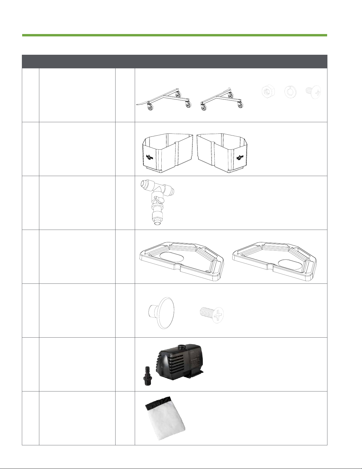
Description Qty
ACaster Unit
• Left Caster Frame
• Right Caster Frame
• Assembly Kit
1
1
1
Left Right Assembly Kit
BTanks
• Left Tank
• Right Tank
1
1
Left Right
CDrainage Valve 1
DLids
• Left Lid
• Right Lid
1
1
Left Right
ETank Knobs
• Knobs
• Screws
2
2
Knob Screw
FPump 1
GPump Filter Bag 1
ScrewNut Lock
Washer
9
Flex Farm AssemblySection 2
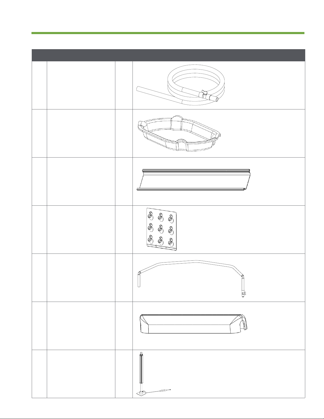
Description Qty
HVertical Irrigation
Line
1
ILid Plugs 2
JRoot Chambers 8
KPanels 32
LDrip Lines
• Left side has
Y-tting attached
2
MTop Caps 8
NLight Tower 1
10
Section 2Flex Farm Assembly
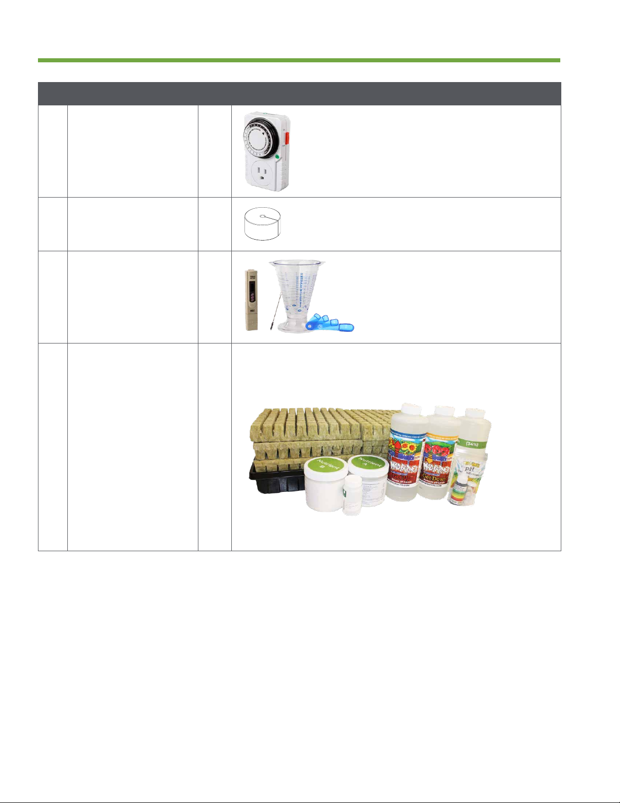
Description Qty
OLight Timer 1
PPanel Plugs 150
QGrower Toolkit
• TDS Meter
• Measuring Cup
• Measuring Spoons
• Bristle Brush
1
1
1
1
RSupply Kit
• Rockwool Flats
• Nursery Tray
• Nutrient A (1 lb)
• Nutrient B (1 lb)
• pH Test Kit
• pH Down (1 qt)
• pH Up (1 qt)
• Food Grade
Hydrogen
Peroxide (1 qt)
• Seeds (jar)
4
1
1
1
1
1
1
1
1
11
Flex Farm AssemblySection 2
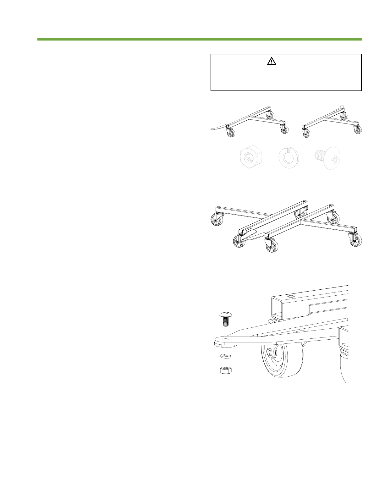
Assemble Caster Unit
1. Locate the caster unit (A) and an
adjustable or 3/8 inch wrench (optional).
NOTE: If your caster unit came
pre-assembled, skip to step 5.
2. Set the right and left sides of the caster
frame side-by-side on the oor, wheel
side down.
3. Line up the holes on each half and insert
the bolt through the overlapped holes.
4. Add the locking washer followed by the
threaded nut and hand tighten until
connection point is secure.
NOTE: An adjustable or 3/8 inch wrench can
be used to tighten if needed.
5. Set caster unit on the oor
wheel side down.
The pH solutions and hydrogen peroxide are
caustic materials. Keep out of reach of children.
Handle carefully to avoid personal injury.
Caution
A

12
B
F G
D
H I
E
C
Assemble Tanks and Pump
1. Gather two tanks (B), drainage valve
(C), two lids (D), two tank knobs (E),
pump (F), pump lter bag (G), vertical
irrigation line (H), two lid plugs (I),
hair dryer (optional) and Phillips head
screwdriver (optional).
2. Connect the 3/4 inch vinyl tubing
attached to the back of both tanks to
the drainage valve.
NOTE: A hair dryer can be used to soften
the end of the tubing to ease assembly.
3. Hand tighten each end of the drainage
valve around the 3/4 inch vinyl tubing
and ensure the drainage valve is in the
closed position.
Section 2Flex Farm Assembly
Ensure tubing is securely attached. Improper
connection of tubing to either elbow or drainage
valve can cause leaking.
Notice
13
Section 2Flex Farm Assembly
4. Place the tanks on the caster unit,
aligning the caster frame to the grooves
in the bottom of the tanks.
NOTE: When properly assembled, the
drainage valve will be positioned directly
above where the caster unit halves are
attached to one another.
5. Attach one tank knob to each tank lid by
inserting a screw through each pilot hole
in the lid from the inside and twisting on
the knob by hand until tight.
NOTE: A Phillips head screwdriver can be
used to tighten tank knob if needed.
6. Put the tank lids on the tanks. Position
the large oval holes and tank knobs
closest to where the tanks separate.
NOTE: Place the lid with the small round
hole on the left tank.
14
7. Take the pump out of the box and attach
the 1/2 inch tting (included with pump).
8. Set the pump on top of the left tank lid
and thread the power cord down through
the large oval opening and then back
out of the tank through the small round
opening in the lid.
9. Identify the end of the vertical irrigation
line farthest from the valve. In the
opposite direction as the power cord,
insert this end into the tank through the
same round opening.
10. Pull the vertical irrigation line out of the
tank through the large oval opening and
connect it to the 1/2 inch tting attached
to the pump.
Flex Farm AssemblySection 2
15
11. Place the pump into the pump lter bag,
allowing the power cord and vertical
irrigation line to exit the bag.
12. Tie the pump lter bag closed and place
the pump into the bottom of the tank
through the oval opening.
13. Gently pull the vertical irrigation line and
power cord exiting the tank to position the
pump near the back of the tank.
14. Insert a lid plug into the oval opening in
each tank.
Light will cause algae to bloom when it comes in
contact with Flex Farm water. Keep the lid plugs
inserted into the lids to prevent light from getting
into the tanks. Only remove the lid plugs to add
water or access the water supply.
Notice
Section 2Flex Farm Assembly

16
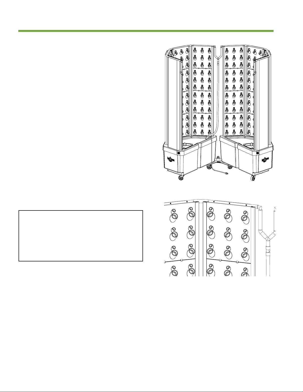
Assemble Root Chambers
and Panels
1. Gather eight root chambers (J), 32 panels
(K), two drip lines (L) and eight top caps (M).
2. Identify the side of the root chamber
without notches. Insert that side into the
tank through a slot in the tank lid. Repeat
until all eight root chambers are inserted
into the tank.
NOTE: A properly installed root chamber will
rest at and t around the raised area located
on the bottom of the tank with all notches
pointing upward.
J L
M
K
Flex Farm AssemblySection 2
17
3. Insert four panels, one at a time, into the
top each root chamber by sliding them
through the rails located on each side.
NOTE: Insert panels tab side rst into root
chambers.
A
B C
Section 2Flex Farm Assembly
18
4. After all 32 panels have been installed, feed
each drip line through the notches at the
top of the root chambers, ensuring the
valves on each side are positioned closest
to where the Flex Farm opens.
NOTE: The left drip line will have a Y-tting
attached to the vinyl tubing on the opposite
side from where the valve is attached.
5. Connect the Y-tting attached to the left
drip line to the right drip line.
Take extra care to ensure the drip lines are installed
on the correct side with the holes positioned
directly behind each plant space in the top row of
each panel. Placing the drip lines on the incorrect
side may obstruct water ow, and failure to line
holes up with plant spaces may result in leaking
and/or plants not receiving enough water.
Notice
Flex Farm AssemblySection 2
Table of contents
Popular Farm Equipment manuals by other brands


CynkoMet
CynkoMet N-221/3-9 Instructions for Use and Operation

MacDon
MacDon M105 Operator's manual

Chore-Time
Chore-Time LIBERTY 53476 Installation and operator's manual

Miller
Miller AG-BAG Professional LX1214 Operator's manual

Producer's PRIDE
Producer's PRIDE Hill Country Coop Care Instructions

Unverferth
Unverferth ZONE-BUILDER 112 manual

Trejon
Trejon Terradisc 3000 Mounting instructions

Mayer
Mayer 1018 Series manual

Richiger
Richiger R990 Assembly instructions operator's manual parts list

Stara
Stara ASA H Instruction manual and parts catalog

Brouwer
Brouwer ROLLMAX 2400 Operator's manual

Redexim
Redexim Easy Spread 1500 Operator and parts manual