FG Modellsport 10007 User guide

Mounting instruction for
F1 Competition 09 Chassis
Item N°. 10007, 10008
A.10007-10008-200409
FG Modellsport GmbH
Spanningerstr. 2
73650 Winterbach-Germany
Phone: +49 7181 9677-0
Fax: +49 7181 9677-20
www.fg-modellsport.de
Please thoroughly keep this construction manual for spare parts orders!
Weight of the individual bags/ boxes:
Bag A = 4 parts
Bag B = 0,871 kg
Bag C = 0,649 kg
Bag D = 0,617 kg
Bag E = 0,308 kg
Bag F = 0,136 kg
Bag G = 0,699 kg
Bag H = 0,729 kg
Bag I = 0,091 kg
Bag J = 0,125 kg
Bag K = 0,498 kg
Bag L = 0,442 kg
Bag M = 0,502 kg
Bag N = 0,355 kg
Bag O = 0,587 kg, only for Item N°. 10007
Bag P = 0,447 kg, only for Item N°. 10008
The RCS, accumulators and battery charger are not included in the de-
livery volume.
We congratulate you on buying this FG Competition model. Please check
the contents of the construction set, respectively of the bags. The indi-
vidual bags had been thoroughly packed by us and their weight had been
checked. When purchasing the individual bags, please check their weight
and their closure by staples which must not have been removed or ope-
ned and closed several times. It is possible that the weight of an indivi-
dual bag deviates by 5 grams. In case of claims due to missing parts, you
always need to present the label indicating the weight at your speciali-
zed dealer. By checking the weight of the bag, you may exclude that lar-
ger parts or several parts are missing.

The handling with fuels requires circumspective and ca-
reful handling. Imperatively observe the security advi-
ces.
- Refuel only if the engine is switched off!
- Take off the body.
- Thoroughly clean the area around the fuels nipple.
- Remove the fuel filler cap and carefully fill in the fuel mixture.
- Smoking or any kind of open fire is not admitted.
- Fuels might contain solvent-like substances. Avoid contact with skin and ey-
es. Wear gloves for refueling. Do not inhale fuel vapors.
- Do not spill any fuel. If you have spilled fuel immediately clean the engine
and the model.
- Make sure that no fuel will get into the soils (environmental protection). Use
an appropriate mat.
- Do not refuel in enclosed rooms. Fuel vapors accumulate at the soil (risk of
explosion).
- Transport and store fuels only in admitted and labeled canisters. Keep fuel
out of the range of children.
- The operator is responsible for any damages caused to third persons in the
operating range of the model, respectively of the engine, if they are injured
or in case of property damage.
- The model must only be passed on to persons who are familiar with this mo-
del and its operation, always provide the operating manual.
- Persons with implanted heart pacemakers must not work on running engi-
nes and on live parts of the ignition system when the engine is being star-
ted.
- The engine must neither be started nor operated in enclosed rooms (wi-
thout sufficient ventilation).
- When starting the engine, avoid inhaling the exhausts.
- The model must neither be started nor operated without air filter or without
exhaust system.
- Before every start perform a functional check of the safety-relevant parts.
- The throttle rods must always return automatically to the idle position.
- Any cleaning, maintenance and repair works must only be performed with
the engine being switched off. The engine and silencers are getting very
hot. In particular do not touch the silencer.
Comments regarding the construction manual:
Before starting the assembly please see through this construction manual.
This way you will get an overview of the whole execution.
Please check by means of the parts or bag list if the construction kit is com-
plete and also check the weight of the individual bags for the positions. Only
this way you may be sure that all parts which you need for the assembly are
available. If a part is missing, please immediately contact your specialized
dealer.
Table of contents
Position 1: Differential gear
Position 2-7: Rear axle, gearwheel drive
Position 8: Shock absorber
Position 9-10a: Assembly shock absorber, stabilizer - rear axle
Position 11-19a: Front axle
Position 14-17: Servos, receiver
Position 18-19a: Assembly shock absorber, stabilizer - front axle
Position 12-13: Servo saver, track rods, steering rods
Position 19-23: Engine, manifold, airbox, clutch
Position 23-24a: Engine assembly, tank
Position 25-25a: Tuning pipe
Position 18: Throttle rods
Position 28-29: Front spoiler, rear spoiler
Position 30-31b: FG Magura hydr. brake system front and rear
Position 32-33b: Tuning disk brake front and rear

All metric screws need to be secured
with thread lock fluid.
7080/3
6069/2 8600/13
8600/3 8600/4
8602/1
8493 8600/11
8602/2
8600/13 8600/13
8602/2
8600/2
8600/13
8600/9
8600/10
8493
6924/20
6069/2
7080/3
6924/20
8600/8
6067
6068
8500/3
6067
8600/8
8600/11
8600/1
8600/11
8600/6
Steel gearwheel
large 48t.
Screw M4x8
Flat side
O-ring
Ball diff.
axle
Assembly
The flange bushes 8602/2, roller bearing 8602/1 as well as the rotary shaft se-
als 8600/6 and the ball bearing 8493 have professionally been mounted on
the alloy differential housing A/B by the manufacturers FG .
Now mount the steel gearwheel 48 teeth on the alloy differential housing A.
Check the internal and external fins on production birs, if necessary remove
them with an emery cloth. Do not bend the fins.
Now mount the set of fins according to illustration 1: Insert a differential ge-
arwheel with square on a differential bevel wheel axle. Then slide on the
square one after another in the following order 1x internal fin, 1x O-ring 14x1.5,
1x external fin, 1x internal fin, 1x O-ring 14x1.5, 1x external fin, 1x internal fin,
1x external fin. Grease the shim ring 8600/13 a little and put the differential
housing on the flange bush 8602/2. Now insert the whole package into the
differential housing A according to the illustration. Now push the differential
gearwheel with a screw driver with the fin package towards the housing and
carefully pull out the differential axle.
Push both bronze bushes 8600/8 from the inside to the outside into the bo-
rings of the differential housing, position 1a. Insert the differential gearwheels
B into the housing and push in the differential bevel differential gear axle
6068. Grease the 8mm shaft of the ball diff. axle 6069/2 plentifully and push
it from outside into the differential housing. The borings of the alloy diffe-
rential housing need to align with the borings of the differential gearwheels.
If the borings are offset, the gearwheels need to be disassembled and reas-
sembled once again displaced by one tooth until the parts can be easily tur-
ned. Mount the O-rings 3x1 and 42x1.5 according to the illustration.
Now join the two halves of the housing, check them for free movement and
assemble them using the two enclosed M3x20 screws.
Fill in about 15ml of the enclosed silicon oil into the boring of the alloy diffe-
rential housing B. Add about 5ml 2-stroke engine oil for better lubrication. Then
close the boring by means of the locking screw M8x1/ copper disk. You may
influence the locking effect by the number of fins by the viscosity of the fil-
led in oil as well as by the filling quantity.
When driving an overpressure is building up in the diff. housing. Therefore you
should unscrew the locking screw after a few laps of driving time in order to
release the overpressure.
Insert the fin package
into housing A.
O-ring 42x1,5
O-ring 3x1
Bronze bush
7x18x5
Position 1
Parts are in
bag C
Position 1b
Parts are in
bag C
Position 1a
Parts are in
bag C

Press the bearing shafts into the right alloy rear axle mounts
and mount the alloy cross bracing with M4x18 countersunk
screws to the left and right alloy rear axle mounts.
Before assembling, impress the alloy diff. bearings into the gui-
dings of the left and right alloy rear axle mounts and check if they
are running smoothly, it may be necessary to rework the gui-
dings a little with an emery cloth. Then press them on the ball
bearings of the pre-assembled differential and press them in
evenly (with the gearwheel in direction to the left alloy rear ax-
le mount) into the left and right alloy rear axle mounts. Mount the
alloy diff. bearings to the alloy rear axle mounts by using pan-he-
ad screws M5x14.
Insert the body supports in the left and right alloy diff. bearings,
align the borings for the body clips in driving direction and clamp
them by using headless pins M4x10.
Mount the complete gearwheel drive on the alloy chassis by
using M4x14 countersunk screws.
Hint: The left and right alloy diff. bearings are different, please pay
attention to the mounting direction. Make sure that the gearw-
heels are running smoothly. If this is not the case, look for the re-
ason and remedy the defect, mount it again, if necessary.
Position 2
Parts are in
bag A+B
CFRP chassis
right side part
Drivingdirection
Disk Ø 4,3
Screw 4x8
Stop nut
M5
Alloy chassis
Screw
5x25
Screw
5x30
Screw 3x6
Ball bush
Rear lower alloy
wishbone
CFRP chassis
left side part
Bevel
washer
Bevel
washer
Alloy bush
5x10x5,5
Position 3
Parts are in
bag C+D
Alloy rear axle
mount right
Ball bearing
8x16x5
Distance
bush
11x8x1
Ball bearing
8x16x5
Bearing
shaft
Gearwheeel
38 teeth
Distance
bush
11x8x6
Guide bush
Guide bush
Differential
mounted
Alu-Quer-
verstrebung
Alloy cross
bracing
Alloy rear axle
mount left
Screw
4x18 Screw 4x18
Screw
4x18
Headless
pin 4x10
Headless
pin 4x10
Alloy wish-
bone fixing
M4
Alloy wish-
bone fixing
M4
Plastic wish-
bone fixing
Ø4
Plastic wish-
bone fixing
Ø4
Screw
4,2x19
Screw
4,2x19
Left alloy
diff. bearing
Screw
5x14
Screw
5x14
Screw
5x14
Body support
Disk
Ø 5,3
Disk
Ø 5,3
Screw
5x14
Alloy chassis
Position 4
Parts are in
bag C+D
Alloy rear
axle mount
right
Alloy rear
axle mount
left
Screw
4x14
Screw the CFRP chassis side parts to the al-
loy chassis using M4x8 pan-head screws and
disks Ø4,3.
The CFRP chassis side parts left and right
differ, pay attention to the mounting direction.
Impress the ball bushes into the alloy
wishbones and secure them with M3x6
pan-head screws.
Mount the rear lower alloy wishbones to the front alloy chassis by using M5x25
countersunk screws, bevel washers and stop nuts M5. Fix the rear alloy wish-
bone by using M5x30 countersunk screws, alloy bushes 5x10x5,5 (between al-
loy chassis and bevel washer), bevel washers and stop nuts M5.
Mount the bevel washers always with the thinner side facing towards the ball bush.
Press the guide bushes into the alloy rear axle mounts.
Mount the lower alloy wishbone fixings M4 and the upper
plasic wishbone fixings Ø4 to the alloy rear axle mounts
by using M4x18 and 4,2x19 countersunk screws. Press
each 2 ball bearings 8x16x5 and a distance bush 11x8x1
into the gearwheels 38 teeth, then insert the bearing shafts
from the square side. Now press the bearings shafts with
the distance bushes 11x8x6 into the left alloy rear axle
mount and fix them by using M5x14 pan-head screws and
disks Ø5,3.

Push the distance disks into the round recess of the ball driving
axle as well as into the ball diff. axle. Mount the protection bellows to the ball dri-
veshafts according to the illustration. Lubricate the ball range a little when put-
ting on the protection bellow. Apply lubrication grease on the ball holes of the dri-
veshafts and press in the balls. The balls will be held by the lubrication grease
and this way the driveshaft can be mounted more easily. Now press the complete
ball driveshaft into the ball differential axle and the ball driving axle. Shift the pro-
tection bellows over the ball diff. axles and the ball driving axles.
Position 7
Parts are in
bag B
Driving
shaft
mounted
Left alloy
upright
Headless
pin 6x6
Wheel nut
M6
Square wheel
14 mm
Screw
4x12
Distance
bush
Ball bearing
8x22x7
Ball bearing
8x22x7
Pay attention
to the slant
Screw
5x16
Screw
5x16 Screw
5x20
Rear axle
plate left
Screw
5x20
Bevel
washer
Driving direction
Track rod
mounted
Screw
2,9x13
Screw
2,9x13
Rear upper
wishbone
left mounted
Screw
4x35
Screw
4x35
Ball diff. axle
Alloy rear axle
mount left
approx.
21,5mm
approx.
39mm
approx.
10,5mm
Hint: The left and right upper wishbones are different,
mounting direction of the steel ball with collar on the
alloy upright is showing to the bottom and the shorter
side faces the rear. The clearance of the balls in the
ball-and-socket joints can be adjusted with the help of
the screws 2.9x13. The left and right rear axle plates
differ, pay attention that the slant shows to the top when
assembling.
Apply
lubrication
grease.
Lubricate ball driveshaft a little.
Protection bellow
Ball diff. axle
Ball driving
axle
Distance
disks Balls for dri-
ving shaft
Position 5
Parts are in
bag B
1. Press the cylinder pins into the square wheel 14mm as
described in position 6, use high-strength screw reten-
tion.
Press the ball driving axles of the pre-assembled dri-
veshafts into the alloy uprights which are equipped with
ball bearings and then mount the square wheel driver
14mm with recess facing the ball bearing on the flat si-
de of the ball driving axle by using the headless pins
M6x6.
Mount the alloy upright between alloy upright and alloy
wishbones using a countersunk screw M5x20 and bevel
disk (thin side facing the ball bush). The left and right al-
loy uprights are different. The milled surface for the bra-
ke has to face the rear.
2. Mount 2,9x13 pan-head screws into all
plastic ball-and-socket joints.
Mount the pre-assembled upper wishbones
and track rods to the alloy rear axle mounts
using the pan-head screws M4x35.
Fix the rear axle plates with the slant showing
upwards to the alloy uprights by using M5x16
pan-head screws.
Mount the upper wishbones to the rear axle
plates using countersunk screws M5x20.
Mount the track rods to the rear axle plates
using cylinder screws M4x12.
Hint: The left and right track rods are diffe-
rent, pay attention to the balls in the ball-and-
socket joints, mount the ball with lowering
using the cylinder screw.
All metric screws need to be secured with thread lock fluid.
Position 6
Parts are in
bag B
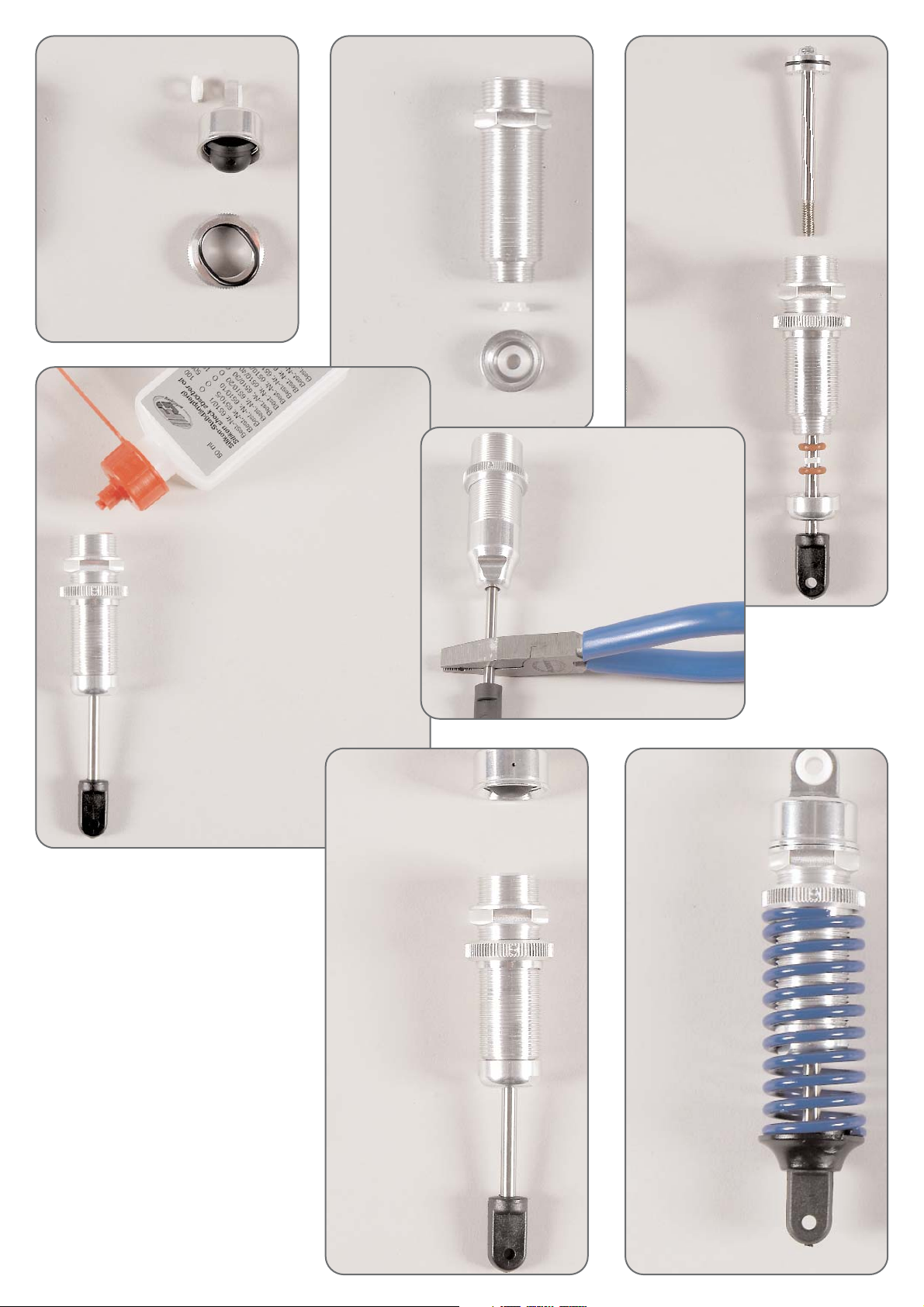
Position 8
Parts are in
bag E
Position 8a
Parts are in
bag E
Position 8b
Parts are in
bag E
Position 8e
Parts are in
bag E
Position 8c
Parts are in
bag E
Position 8d
Parts are in
bag E
Disk
Ø 4,3
Disk Ø
4,3
Rear alloy
baffle
Screw
5x25
Disk
Ø 5,3
Ball bearing
7x11x3
Headless
pin 4x20
Headless
pin 4x20
Nut
M4
Alloy damper
reversing
Alloy dam-
per rever-
sing
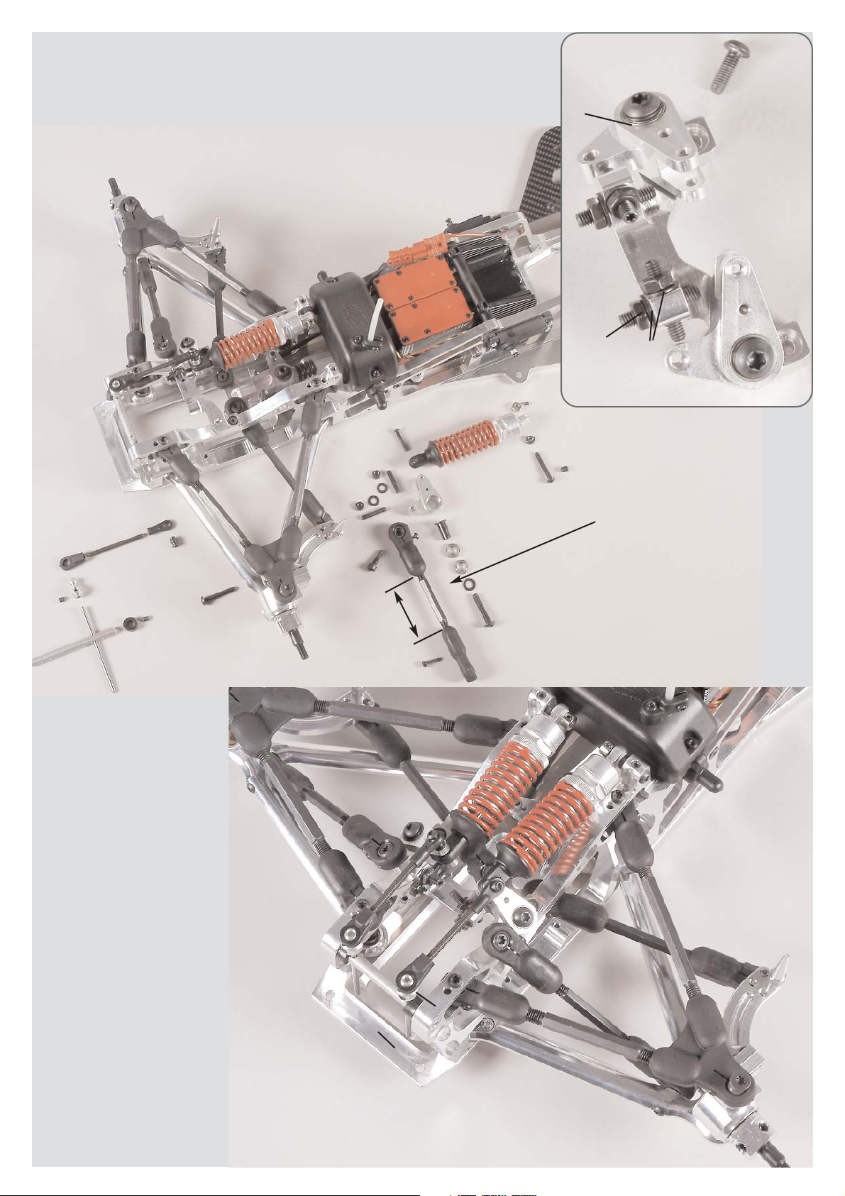
Screw the ball-and-socket joints
6mm and 7mm on the rods to the
length of approc. 72mm, then
press the steel balls 6mm and ball
collets 7mm in the same direc-
tion into the ball-and-socket jo-
ints 6mm and 7mm.
Mount the stabilizer into the ball
collets 7mm with an excess
length of approx. 8mm by using a
headless pin M4x4.
Press the stabilizer shaft with
shim rings 6x12x1 between the
alloy rear axle mounts, insert the
two stabilizer rods in the stabilizer
shaft, connect the stabilizer rods
with the shim rings between the
alloy rear axle mounts and mount
them using headless pins M4x4.
Mount the ball-and-socket joint
with steel ball 6mm to the inside
of the damper reversings using
pan-head screws M3x16. Pay at-
tention to position 10a.
Screw
5x25
Push-Rod
mounted
Screw
2,9x13
approx.
53mm
Position 9
Parts are in
bag F
Position 10
Parts are in
bag F
Stabilizer
Stabilizer shaft
Ball collet
7mm
Ball joint
7mm
Linkage
Headless
pin 4x4
Shim ring
6x12x1
Screw
3x16
Stop
nut M4
Damper fixing
brace
Disk
Ø 4,3
Screw
4x12
Rear alloy
baffle
Screw
4x14
Disk
Ø 5,3
Screw
5x25
Ball bearing
7x11x3
Ball joint
6mm
Steel ball
6mm
Screw
4x20
Nut
M4
Screw
3x12
Bearing
bush
Nut
M4 Disk Ø
4,3
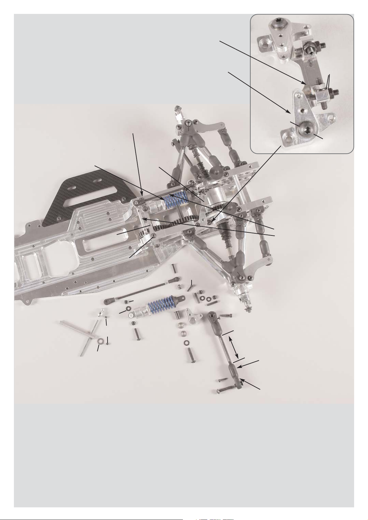
Assemble the M4x20 pan-head screws into
the damper fixing brace and secure them
with M4 nuts. Now mount the fixing brace
to the alloy rear axle mounts by using M4x12
pan-head screws and Ø4,3 disks.
Screw the M4x20 headless pins into the alloy baffle as pic-
tured and secure them by using Ø4,3 disks and M4 nuts.
Mount the alloy baffle to the alloy rear axle mounts using
M4x12 pan-head screws.
Press the ball bearing 7x11x3 into the alloy damper rever-
sing, insert the bearing bushes through the alloy damper re-
versings which are equipped with ball bearings and mount
them to the alloy baffle using M5x25 pan-head screws and
Ø5,3 disks.
Fix the rear dampers to the damper fixing bra-
ce by using Ø4,3 disks and M4 stop nuts.
Fix the front dampers from the outside at the
alloy damper reversings with M3x12 pan-head
screws.
Mount the 2,9x13 pan-head screws in-
to the plastic ball joints of the push-rods.
Fix the pre-assembled lower push-rod
with the collar of the steel ball to the re-
ar lower alloy wishbones by using
M5x25 pan-head screws.
Mount the pre-assembled upper push-
rod to the alloy damper reversings by
using M4x14 cylinder screws.
Hint: Left and right push-rods are diffe-
rent, pay attention to the balls in the ball
joints, mount the ball with lowering with
the cylinder screw. An arising clearance
in the ball joints can be adjusted with
the 2,9x13 screws.
All metric screws need to be secured with thread lock fluid.

Alloy servo saver A 04
ball-beared
Alloy servo saver B 04
ball-beared
Flange sleeve for
alloy servo saver
Servo saver spring
Servo saver axle
Countersunk screw M5x25
Securing disk 6mm
Shim ring 7x13x0,3
O-rings
Ball bearing 7x14x5
Ball bearing
7x11x3
Position 12
Parts are in
bag H
approx. 8mm
approx. 72mm
Screw
4x14
Screw
4x14
Stop nut
M5
Screw
3x6
Screw
3x6
Bevel
disk
Bevel
disk
Front axle
carrier right
Alloy chassis
Alloy front
chassis
Position 11
Parts are in bags
G+A+H
Front lower alloy
wishbone left
Ball-type
nipple
Screw
5x25
Screw
5x25
Body mount
Screw
4,2x19
Position 10a
Parts are in
bag F
The stabilizer rod should be mounted pa-
rallel to the shock absorber.
Make sure the stabilizer 3mm projects ap-
prox. 8mm at the top. Please check if the
stabilizer does not contact any other parts
when deflecting.
Secure the ball-type nip-
ples which are moulded
in the alloy wishbones
using the binding head
screws M3x6.
Mount the front lower alloy wishbone with the shorter side facing the front to the
alloy chassis and the alloy front chassis by using M5x25 countersunk screws, be-
vel disks and M5 stop nuts. Mount bevel disks always with the thinner side facing
the ball-type nipple.
Fix the body mounts to the left and right front axle carriers using 4,2x19 countersunk
screws. Mount the right front axle carrier to alloy chassis and alloy front chassis
with M4x14 countersunk screws.
Push the ball bearing in the alloy servo saver parts A and B. Mount the
servo saver spring on the alloy servo saver part A, then mould the flan-
ge sleeve in the alloy servo saver part A. Press the servo saver axle
through the flange sleeve into the two servo saver parts and secure it
using the shim rings and the securing ring 6mm. Check if the servo sa-
ver is running smoothly, mount the o-rings on the servo saver.
Hint: You can adjust the effect of the servo saver with the number of the
used o-rings. The more o-rings, the harder is the effect of the servo sa-
ver.
All metric screws need to be secured
with thread lock fluid.
Servohebel
Screw
3x18
Screw
4x20
Screw
2,9x13
Ball joint
Ball joint
6mm
Alloy joint
ball
Track rod
mounted
Steering rods
mounted
Stop nut
M4
Stop nut
M3
Steel ball
6mm
Servo saver
mounted
Position 13
Parts are in
bag H
approx. 45mm
Front axle
carrier right
Screw
3x18
Screw
4,2x16
Screw
5x25
Distance
disk
Distance
bolt
Stop nut
M3
Steering servo
Steering servo
Servo fixing
brace
Steering rods
mounted
Disk Ø
5,3
Screw
4,2x19
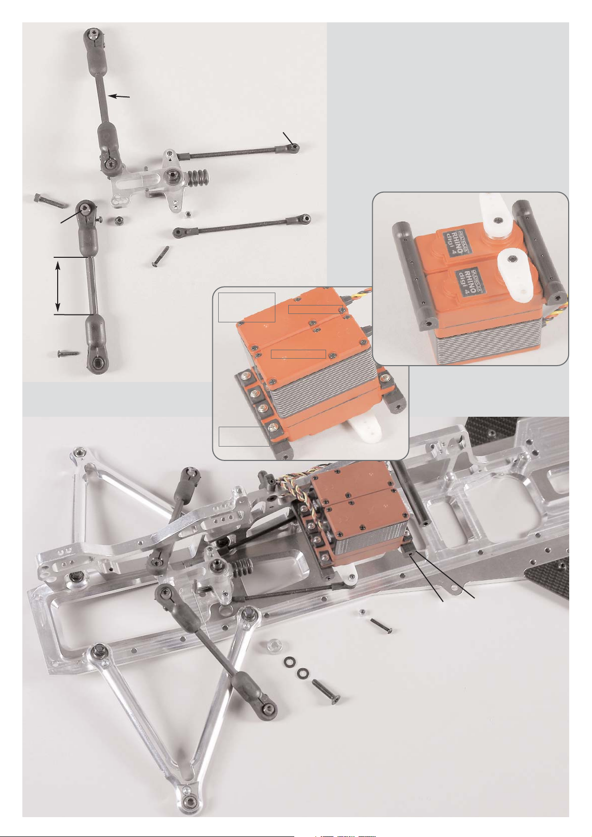
Mount the assembled steering rods through the steel balls 6mm with
the collar facing the servo saver into the outer thread holes of the al-
loy servo saver by usin g M3x18 pan-head screws and secure them
with M3 stop nuts. Screw 2,9x13 pan-head screws into the plastic
ball-and-scket joints of the track rods.
Fix the mounted track rod into the front outer hole of the servo saver
by using M4x20 cylinder screws. The cylinder screw must go through
the alloy joint ball, the collar must face the alloy servo saver. Fasten
it all with M4 stop nuts.
Hint: The ball clearance can be adjusted with the 2,9x13 screws in the
ball-and-socket joints.
Steering servo
Steering servo
Servo fixing
brace
Position 14
Parts are in
bag H
Mount the steering servos with the enclosed fi-
xing rubber bushings and screws to the servo fi-
xing braces as described in position 14. Switch on
your RCS and bring the steering servos in neu-
tral position. The servo arms have to be shortened
slightly corresponding the type. For competition
we recommend to use alloy servo arms. Press the
servo arms on the servos as pictured and fix them
with the enclosed screws. Preferably the servo
arms should be in a 90° position to the servo.
Mount the servo fixing braces on the right front axle carrier by
using 4,2x16 countersunk screws.
Mount the distance bolt with a 4,2x19 countersunk screw to
the right front axle carrier.
Mount the servo saver with a M5x25 countersunk screw, Ø 5,3
disk and distance disk between servo saver and alloy chas-
sis in the rear hole of the alloy chassis.
Switch on the RCS, bring the trim of the steering into central
position. Align servo saver in centre of the chassis. First mount
one servo rod using M3x18 pan-head screw and M3 stop nut,
then the second in the same way. Adjust both servo rods in
the same length. You should be able to fix the servo rods ea-
sily and without any resistance on the servo arms of the stee-
ring servos.
Hint: Adjust both steering rods in the same length by turning
the ball-and-socket joints. Servo saver and servo arm should
be parallel.
Servo arm
Steering servo
Servo fixing
brace
Position 14
Parts are in
bag H
Position 15
Parts are in
bag H
Disk
Ø 4,3
Front axle
carrier left
Screw
4x14
Screw
4x14
Screw
4x14
Alloy battery
fixing brace F1
Drill the alloy battery
fixing brace F1 to
7mm if using the 3rd
receiver fixing.
Alloy
chassis
Screw
2,9x13
Receiver
battery
Body mount
Body clip
Dampening
rubber
Battery/
body bolt
Screw
2,9x9,5
Screw
2,9x19
Screw
2,9x16
Receiver box
Flexible aerial
Mount for flexible aerial
Stop
nut M4
Mount the left front axle carrier to the
alloy chassis and the alloy front chas-
sis using M4x14 countersunk screws .
Mount the servo mounting brace to the
left front axle carrier using 4.2x16
countersunk screws. Mount the dis-
tance bolt to the left front axle carrier
using a 4.2x19 countersunk screw.
Mount the throttle-brake servo and the
brake servo to the front axle carrier
using M2.5x12 pan-head screws.
Drill out the aerial hole by 3mm at the
lid of the receiver box and mount the
aerial mount to the lid of the receiver
box using a 2.9x19 pan-head screw.
Insert the flexible aerial through the fle-
xible aerial mount and clamp it with a
2.9x9.5 pan-head screw.
In order to lead-in the servo cables, cut
out a hole of a diameter of approx.
10mm at an appropriate position bet-
ween the lower and upper part of the
box.
Put the lower part of the box on the
body mounts. Connect all servo ca-
bles and battery cables to the receiver
and check if it is working properly. Le-
ad-in the aerial cable through the ho-
le of the upper part of the box and
through the flexible aerial. Now stow
the cable remnants of the servos in the
receiver box, mount the lower and up-
per part of the receiver box to the bo-
dy mounts using the 2.9x16 pan-head
screws.
Hint: Cover the lower part of the re-
ceiver box with some foam in order to
protect the receiver against vibrations.
Position 16
Parts are in
bag I
Position 17
Parts are in
bag G+H
Track rod
mounted
Alloy
steering
stop
Wheel nut M6
approx. 71mm
approx. 62mm
Retaining
washer Ø 5
Driving
axle
Square
wheel
14mm
Alloy
steering
arm
Bevel
disk
Left alloy
uprights axi-
ally displaced
Distance
bush
Ball bearing
8x22x7
Front upper
wishbone
left mounted
Screw
5x25
Screw
3x10
Screw
4x14
Screw
4x18
Screw
5x20
Screw
2,9x13
Screw
4x25
Screw
4x25
Headless
pin 6x6
Front axle
carrier left
Ball
bush
Position 16a
Parts are in
bag I
Brake servo
Brake servo
Cable clip
Receiver
battery
Throttle-
brake servo
Throttle-
Brake servo
Screw
2,5x12
Push the securing disk in the 2nd groove of the driving axles, then in-
sert it in the alloy uprights equipped with ball bearings according to
the illustration position 17. Then, mount the square wheel driver 14mm
with recess facing the bearing on the flat side of the driving axle by
using M6x6 headless pins. Mount the alloy steering arm to the alloy
uprights using M3x10 pan-head screws. Mount the alloy uprights using
M5x20 countersunk screws and bevel disk (thin side facing the ball-ty-
pe nipple) between the alloy upright and the front lower alloy wishbo-
ne. Mount the pre-assembled upper wishbones to the front axle car-
riers using M4x25 pan-head screws. Mount the upper wishbones to
the outside of the alloy uprights using M5x25 countersunk screws. Fix
the alloy steering stops to the alloy steering arms (front outer thread bo-
ring) by using M4x18 pan-head screws. Mount the track rods to the al-
loy steering arms (rear inner thread boring) using M4x14 cylinder screws.
Hint: Pay attention to the mounting direction of the upper wishbones,
mount the shorter side facing the front. The front alloy uprights are axi-
ally displaced, mount the side with the two threaded holes facing the
top.
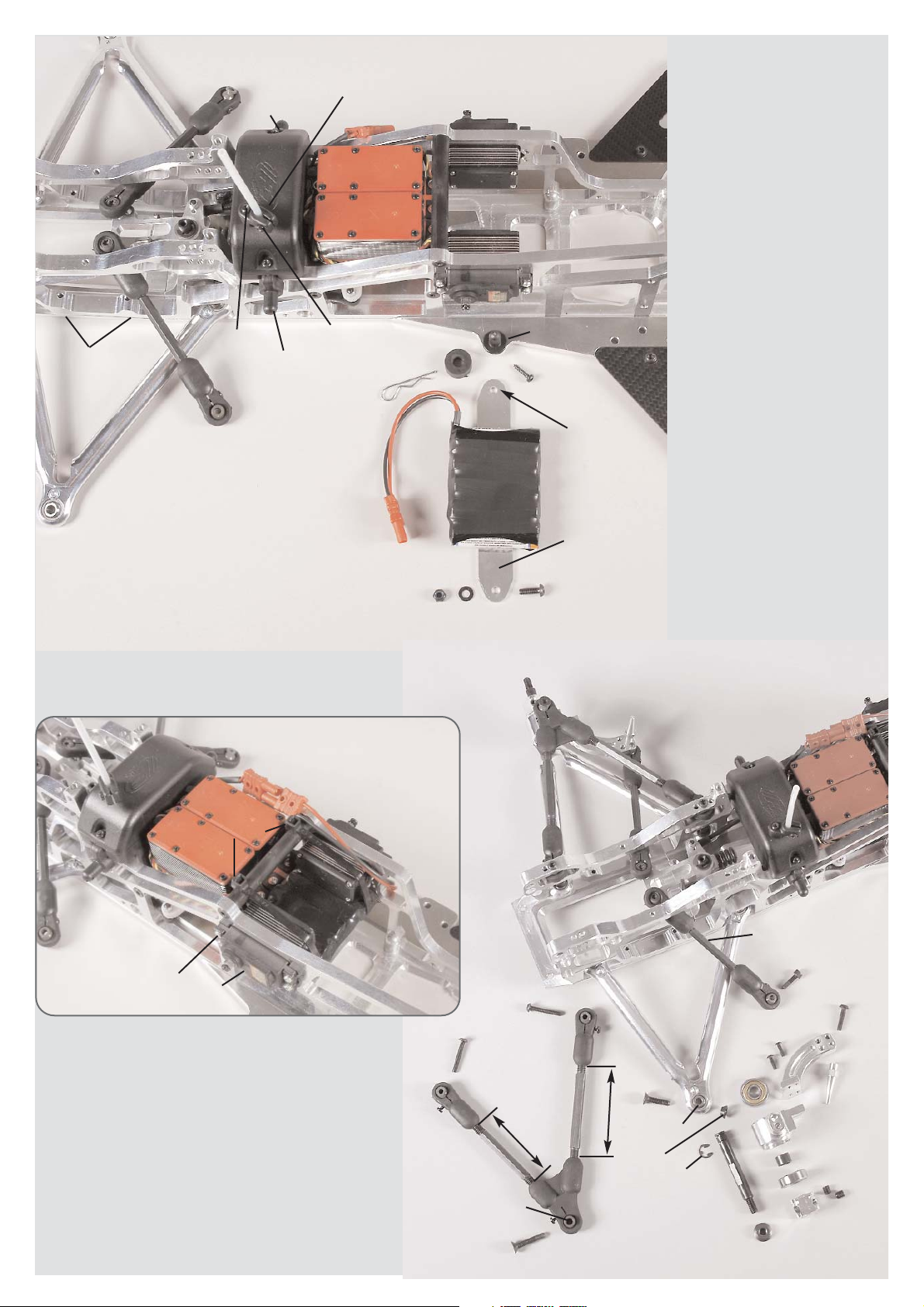
There are 3 possibilities to fasten the receiver battery:
1. Fix the receiver battery from the bottom to the throttle-brake servo
and brake servo using cable clips as illustrated in position 16a.
2. Fix the receiver battery with adhesive tape centred on the alloy bat-
tery fixing brace F1. Now mount the alloy battery fixing brace F1 under
the throttle/brake servo and brake servo on both sides of the alloy chas-
sis by using M4x14 pan-head screws, disks Ø 4,3 and M4 stop nuts.
3. Drill the fixing holes of the alloy battery fixing brace F1 on both sides
to 7mm and fix the receiver battery with adhesive tape centred on the
F1 fixing brace. Mount the battery/body bolts on both sides of the al-
loy chassis using 2,9x13 pan-head screws. Fix the alloy battery fixing
brace F1 on the battery/body bolts under the throttle/brake servo and
brake servo with dampening rubber and body clip.
Hint: The 3rd mounting version of the receiver battery enables a quick
changing of the receiver battery.
Ball bearing
7x11x3
Alloy dam-
per rever-
sing
Alloy
reversing
plate
Screw
4x12
Screw
5x25
Nut M4
Headless
pin 4x20
Disk
Ø 4,3
Push rod
mounted
ca.30,5mm
Collet
Headless
pin 3x3
Nut M4
Headless
pin
5x5
Screw
4x25
Bearing
bush
Disk Ø 5,3
Screw
5x25
ca. 45mm
Ball bearing
7x11x3
Alloy dam-
per rever-
sing
Screw
4x14
Screw
2,9x13
Screw
4x25
Distance
disk
Screw
3x20
Nut
M4
Disk
Ø 4,3
Headless
pin
4x20
Front axle
carrier right
Front axle
carrier left
Steel
ball
6mm
Ball
joint
6mm
Rods
4x43
Ball
joint
7mm
Ball
collet
7mm
Headless
pin
M4x4
Stabilizer 3mm
Stabilizer
shaft
Headless
pin
M4x4
Position 19
Parts are
bags E+J
Position 19a
Parts are in
bags E+J
Position 18
Parts are in
bags E+J
Mount 2,9x13 pan-head screws into the
plastic ball-and-socket joints of the push
rod. Fix the pre-asssembled push rod
at the bottom to the front lower alloy
wishbones using M4x25 pan-head
screws. Fix the pre-assembled push rod
at the top to the alloy damper reversings
using M4x14 cylinder screws.
Hint: Pay attentin to the balls in the ball-
and-socket joints, mount the ball with
lowering with the cylinder screw. The
clearance of the balls can be adjusted
with the 2,9x13 screws in the ball joints.
Screw M4x20 headless pins centrally in the alloy baffle and se-
cure it with disks Ø4.3 and M4 nuts. Mount the alloy baffle to
the front axle carrier by using M4x12 pan-head screws .
Mould the ball bearings 7x11x3 into the alloy reversing plate,
insert the bearing bushes through the alloy reversing plates
which are equipped with ball bearings and mount it to the al-
loy baffle using M5x25 pan-head screws and disks Ø5.3.
Screw the ball-and-socket joints 6mm and 7mm
on the rods to the length of approx. 30,5mm, then
push the steel balls 6mm and ball collets 7mm in
the same direction into the ball-and-socket joints
6mm and 7mm. Mount the stabilizer flush into
ball collets 7mm using a headless pin M4x4.
Press the stabilizer shaft with distance disks bet-
ween the front axle carriers, insert both stabilizer
rods 3mm in the stabilizer shaft, align the stabi-
lizer rods between the front axle carriers using
the distance disks and mount them with M4x4
headless pins. It may be necessary to grind the
distance disks slightly with an emery cloth. Mount
the ball-and-socket joint with steel balls 6mm,
M3x20 pan-head screws and damper mount of
the shock absorber through the outer hole to the
alloy damper reversing plates. Press M4x25 pan-
head screws into the front axle carriers and se-
cure with M4 nuts and M5x5 headless pins. Press
the shock absorbers onto the protruding threads,
then secure them with collets and M3x3 head-
less pins.
Hint: The stabilizer rods should be mounted pa-
rallel to the shock absorber.

Mount the alloy gear box flange to the alloy rear axle carriers using a
M6x14 pan-head screw and a disk Ø6.4 and mount it to the alloy
chassis using M4x14 countersunk screws and fastening disks. Put on
M4x14 pan-head screws with disks Ø4.3 throughout the front axle
carrier into the alloy gear box flange. Put on a M5x14 screw into the
alloy gear box flange.
Push the clutch bell in the clutch flange bearing which is equipped
with ball-and-socket joints, press on 4 shim rings 10x16x1 and steel
gearwheel with 21 teeth and mount it using M5x5 headless pins.
Mount the clutch flange bearing with M5x30 countersunk screws and
distances 5.1x10x16 between the alloy gear flange and the clutch
flange bearing.
Press 10x19x7 ball bearings on both sides into the alloy bearing bus-
hing, insert a distance bush 13x10x35 in between. Mount the alloy
bearing bush to the alloy gear flange using M5x14 pan-head screws.
Push the alloy gear carrier in the plastic gearwheel with 42 teeth and
press it on to the side of the gear shaft which has the shorter flat sur-
faces. Mount the alloy gear carrier to the surface of the gear shaft
using M5x6 headless pins, secure the plastic gearwheel with 42 teeth
using a spacer washer and a M6x10 pan-head screw.
Impress the gear shaft into the alloy bearing bush equipped with ball
bearings. Mount steel gearwheel 15 teeth using M5x5 headless pins
and secure it in the gear shaft using M6x10 pan-head screws.
Hint: Clutch bell and gear shaft should be almost axially without cle-
arance. Make sure that all gear wheels are correctly geared, check if
the complete unit is running smoothly while turning it.
Position 20a
Parts are in
bag K
Screw
5x30
Screw
5x14
Screw
6x10
Screw
6x10
Centre disk
Clutch bell
Gear shaft
Plastic
gearwheel
42 teeth
Headless
pin 5x5
Headless
pin
5x5
Headless
pin
5x6
Clutch flange
bearing
mounted with
ball bearing
10x22x6
Steel gearwheel
15 teeth
Alloy gear
carrier
Shim rings
10x16x1
Alloy gear
flange
Alloy
bearing
bush
Ball bearing
10x19x7
Distance bush
13x10x35
Distance
5,1x10x16
Steel
gearwheel
21 teeth
Position 20
Parts are in
bag K
Front axle
carrier left
Disk Ø4,3
Screw
4x14
Screw
4x14
Screw
4x14
Fixing disk
Fixing disk
Screw
5x14
Disk
Ø 6,4
Screw
6x14
10531/01
Clutch carrier 05 f. F1, 1 pce.
10530/02
Clutch blocks 05, 4 pcs.
10530/03
Cover disk, 1 pce.
10530/04
Spring guide, 4 pcs. 10530/05
Screw set
10530/05
Screw set
10530/05
Screw set
04416/02
10530/06
Clutch springs, 4 pcs.
To dismount the clutch from the
crankshaft remove the M6x25 coun-
tersunk screw, screw in the M6 he-
adless pin and screw the M8 coun-
tersunk screw against it.
Position 21a
Parts are in
bag L
Position 21
Parts are in
bag L
Fixing disk
11,4x8x5
Alloy engine
flange F1
Headless
pin 4x6
Clutch carrier
Cutout
Screw
5x14
Screw
3x5
Cover disk
Spring
guide
Clutch
spring
Clutch blocks
Screw
6x25
Manifold
Screw
5x16
Silencer gasket
Screw
5x55
Bottom
part inlet
silencer
Screw
5x16
Manifold
Silencer
gasket
Position 22
Parts are in
bag L
Position 22a
Parts are in
bag L
Screw
3x18
Nut M3
Screw
3x4
Fuel pipe
6mm
Carburet
or arm
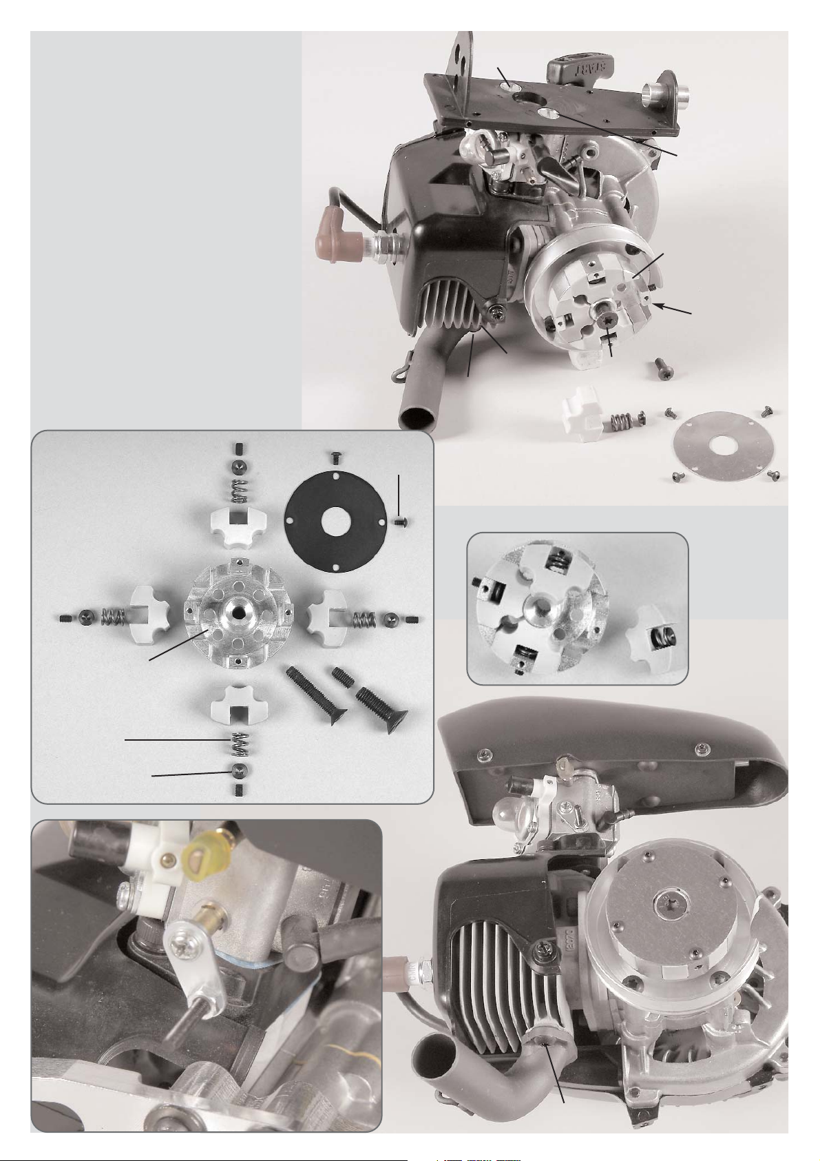
Mount the manifold with silencer gasket and M5x16 pan-head screws
to the engine.
Mount the alloy engine flange to the engine using M5x14 pan-head
screws as illustrated.
In order to mount the clutch, please use the enclosed manual as an aid.
Mount the clutch blocks with clutch springs and spring guides into the
clutch carrier. Screw-in M4x6 headless pins, until they are fitted close-
ly to the spring guide, however, do not pretense the springs. Fasten the
cover disk using M3x5 pan-head screws. Mount the complete clutch to
the engine using an M6x25 countersunk screw.
Disassemble the original air filter and mount the lower part of the inlet
silencer using a fixing disk 11.4x8x5 and M5x55 countersunk screws.
In order to mount the inlet silencer, please use the enclosed manual as
an aid.
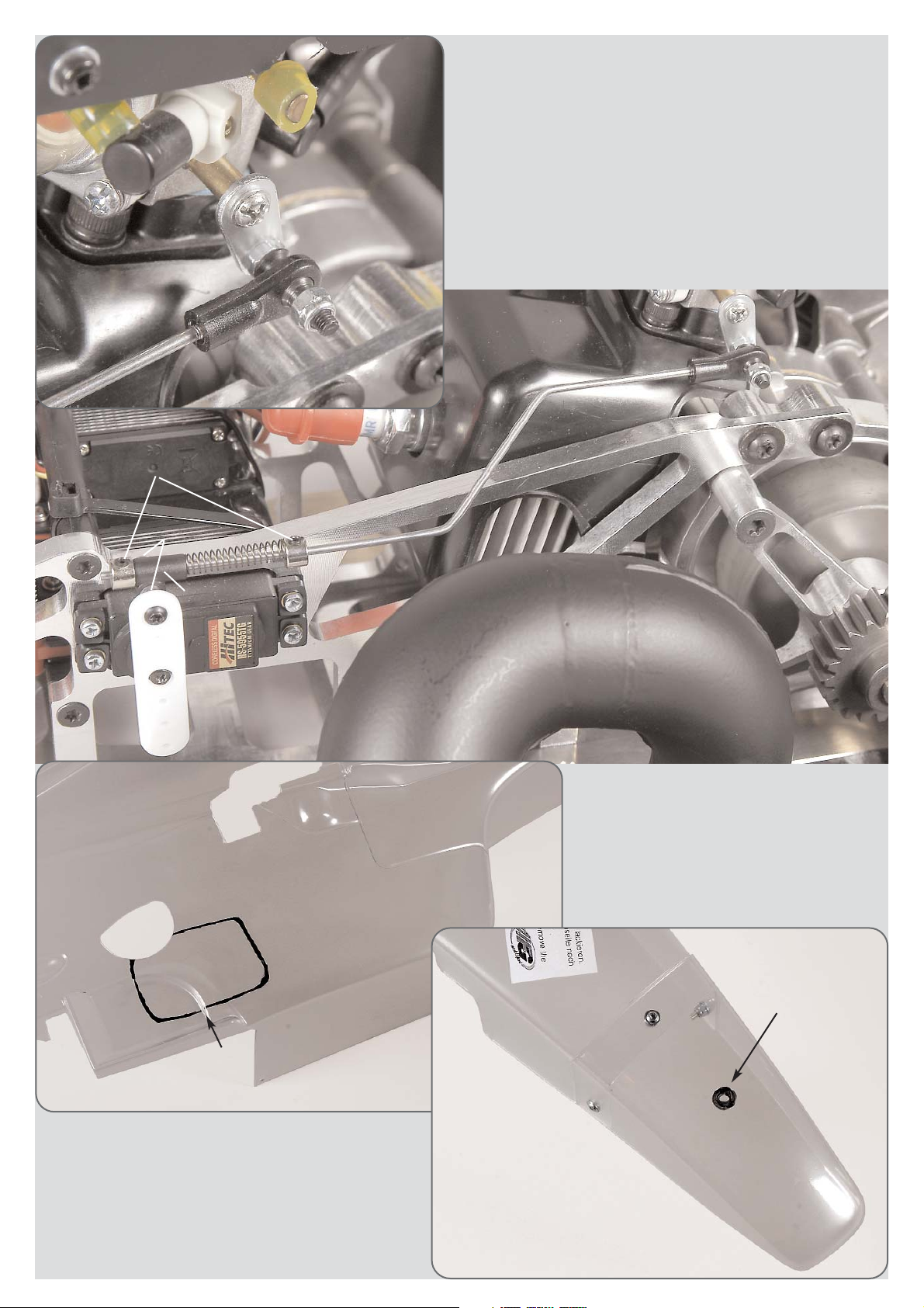
Press M3x18 pan-head screw into the carburetor arm
and secure with M3 nut. Mount the carburetor arm to the
carburetor using an M3x4 pan-head screw, use screw retention and
hold the carburetor arm with a pliers to make sure that the carburetor
arm does not turn the shaft against the stop and bends it.
Pull off the choke lever, cut approx. 6mm off from the yellow fuel pipe
of the tank and press the piece of pipe on the choke shaft instead of the
choke lever.
Hint: Screw-in the headless pin M4x6 with screw retention until it con-
tacts the spring guide. Through an equal screwing-in the spring power
will be increased and the clutch applies later.
Befestigungs-
scheibe
Position 24a
Parts are in
bag L
Position 23
Parts are in
bag L
Disk
Ø 5,3
Screw
5x14
Screw
5x14
Alloy
engine
mount
Screw
5x12
Fixing disk
Fuel hoses
Upper tank
mount
Lower tank
mount
Tank complete
Position 24
Parts are in
bag L
Disk
4,2x16
Tank with mount
assembled
Fixing disk
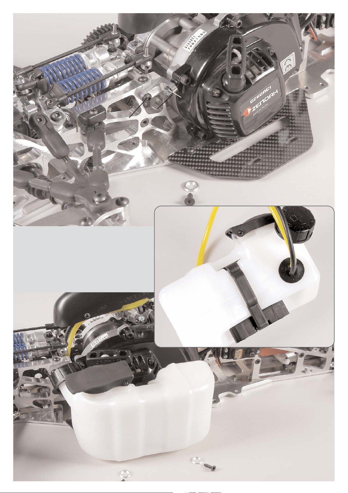
Mount the pre-assembled engine with manifold and air filter in-
to the chassis.Fix the engine with the M5x12 countersunk screws
and engine fixing disks to the chassis.
Mount the alloy engine mount to the engine and the alloy rear
axle carrier using M5x14 pan-head screws, M5x14 hexagon screw
and disks Ø5.3.
Hint: At first, only slightly tighten the engine screws and the
screws for the engine mount. Tighten all screws later when the
complete unit is mounted (in order to avoid warping).
Fix the tank mount complete to the tank as
described in position 24a.
Mount the complete tank at the tank mount
to the CFRP chassis side part using 4,2x16
countersunk screws and fixing disks.
Place the fuel hoses as illustrated on the
following pictures and shorten their length
accordingly. Carefully twist the angle con-
nection at the carburetor for the yellow fuel
hose.
Screw
4x16
Screw
5x14
Screw
4x14
Disk Ø 4,3
Holding strap
Silicone hose
Tension spring
Steel-Power Tuning pipe F1
Steel-Power Tuning pipe F1
Stop nut
M4
Position 25
Parts are in
bag M
Position 25a
Parts are in
bag M
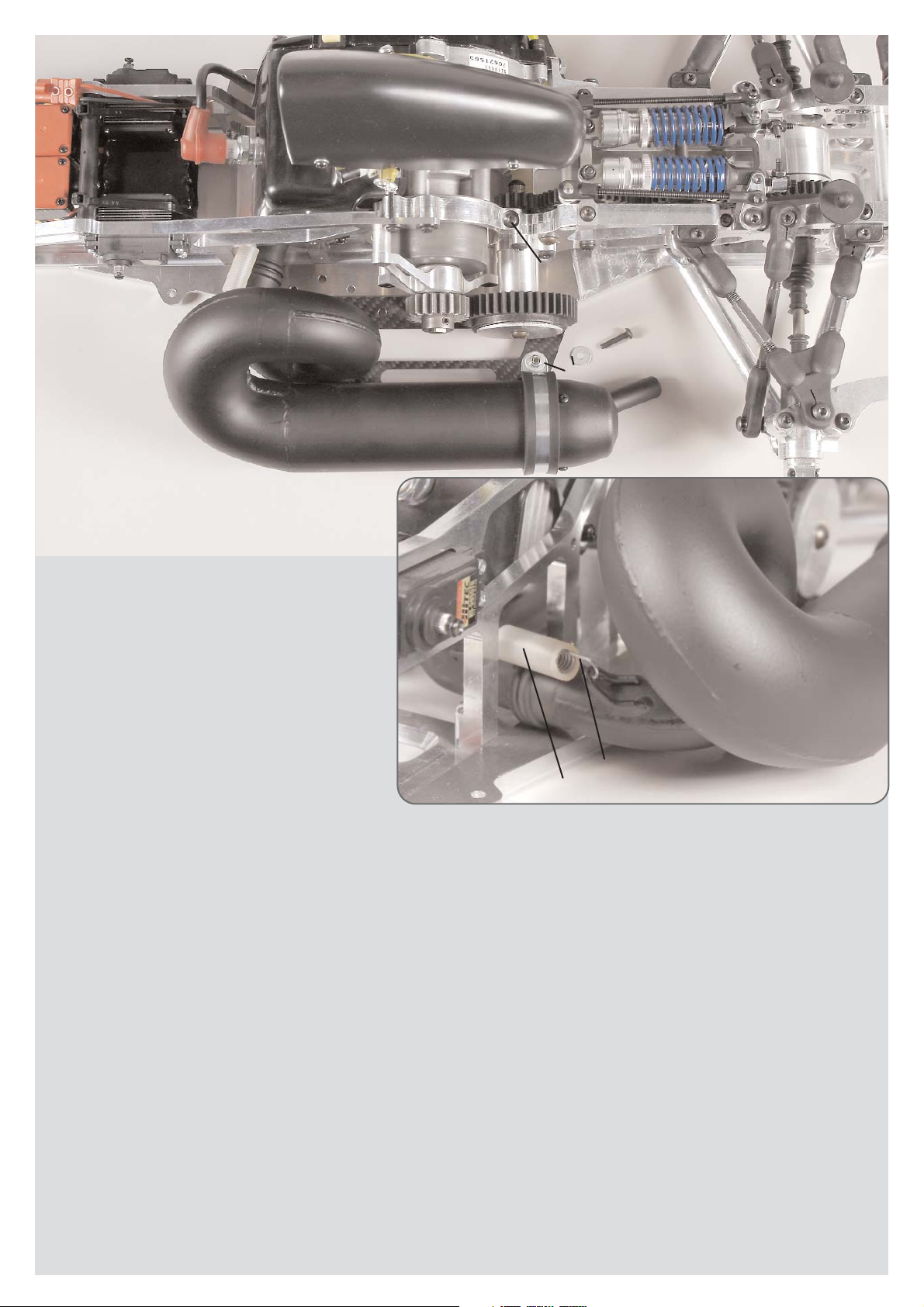
Insert the o-rings into the groove of the Steel-Power Tuning
pipe F1 and moisten them with some 2-stroke oil, then push
the Steel-Power Tuning pipe F1 carefully on the manifold wi-
thout damaging the o-rings.
Press the silicone hose over the tension spring and fasten the
manifold and Steel-Power Tuning pipe F1 with the tension
spring.
Mount the holding strap for the Steel-Power Tuning pipe F1
to the CFRP chassis side part by using the M4x16 pan-head
screw, disks Ø4,3 and M4 stop nuts.
Tighten the M4x14 and M5x14 pan-head screws at the alloy
gear flange.
Position 26a
Parts are in
bag L
Position 26
Parts are in
bag L
Stop nut
M3
Stop nut
M3
Pressure spring
Collet
Collet
Servo
arm
Headless pin
3x3
Throttle pivot
post
Throttle rods
Throttle rods
Screw
3x18
Throttle-brake servo
Mount the ball-and-socket joint of the throttle rods with an M3 stop nut to
the carburetor arm. Make sure the carburetor arm can be moved easily.
Mount the servo arm with the screws which are enclosed in the servos.
Mount the M3x18 screw with the M3 stop nut through the servo arm of the
throttle-brake servos.
Push the collet, pressure spring, throttle pivot post and collet on the thrott-
le rods, press the throttle pivot post on the M3x18 screw in the same time
and mount it in the collets using M3 stop nuts and M3x3 headless pins.
Hint: Do not tighten the M3 stop nut which is on the throttle pivot post,
the throttle pivot post needs to be moved easily. Bend the throttle rods
according to the illustration, they need to run smoothly and should neit-
her touch nor clamp in any position.
Position 27
Position 27a
Cut a sparing for the snap closure of the tank
cap into the bodyshell by using a scissors or
a model knife.
Drill a hole with approx. 8mm
for the adjustable body mount.

Position 28
Parts are in
bag N
Position 29
Parts are in
bag N
Screw
4x18
Disk
Ø 4,3
Stop
nut M4
Screw
2,9x9,5
Screw
2,9x9,5
Screw
4,2x16
Mount for
front spoiler
Polyamide front spoiler
Body clip
Adjustable body
mount
Support for body
mount
CFRP side part
Screw
3x10
Alloy fixing
CFRP wing
top
CFRP wing
bottom
Disk
Ø 5,3
Screw
5x25
Dampening
rubber
Screw
3x10
Assemble the mount for front spoiler to the
polyamide front spoiler using 2.9x9.5 pan-
head screws.
Fix the adjustable body mount to the poly-
amide front spoiler using 4,2x16 countersunk
screws. Mount the support for the body
mount with a body clip.
Mount the polyamide front spoiler to the al-
loy front chassis using M4x18 pan-head
screws, disks Ø4.3 and M4 stop nuts.
Mount the CFRP lower wing to the alloy rear axle carrier with each
2 dampening rubbers between the CFRP lower wing and alloy re-
ar axle carrier using M5x25 pan-head screws and disks Ø5.3.
Mount the CFRP side parts to the lower and upper CFRP wing using
M3x10 pan-head screws and alloy fixings.

Position 30
Parts are in
bag O
Throttle-brake servo
Position 30a
Parts are in
bag O
Position 30b
Parts are in
bag O
Brake pipe
Screw
4x14
Main brake
cylinder
Collet
Headless
pin 3x3
Brake rods
Collet
Headless
pin 3x3
Servo
arm
Collet Throttle pivot
post
Pressure spring
Screw
3x20
Brake pipe
Brake pipe
Cable strap
Brake pipe
Brake disk
Brake caliper
Valve
Protective cap
Screw
3x30
Angle connection
Stop nut
M3
Snap ring for
square wheel
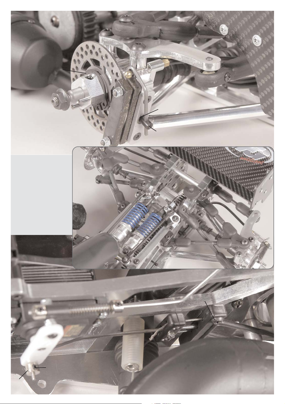
Mount the rear hydraulic brake as described in enclosed
manual. Bend the brake rods corresponding to the illus-
tration and the throttle pivot post. Make sure it is of easy
motion and it does not touch anything. For neutral posi-
tion of the RCS the brake must be released and the gas
must be in neutral gear.
Position 30 - 31 show the Formula 1 Competition 09 Item N°. 10007 with
the FG Magura hydraulic brake system.
007

Position 31
Parts are in
bag O
Brake servo
Servo
arm
Brake pipe
Stop nut
M3
Main brake
cylinder
Screw
4x14
Collet
Headless
pin 3x3
Headless
pin 3x3
Stellring
Brake
rods Pressure spring
Throttle pivot
post
Screw
3x20
Position 31a
Parts are in
bag O
Position 31b
Parts are in
bag O
Angle connection
Brake pipe
Screw
3x30
Protective cap
Valve
Brake caliper
Brake
disk
Snap ring for
square wheel
Mount the front hydraulic brake as described in enclosed
manual. Bend the brake rods corresponding to the illus-
tration and the throttle pivot post. Make sure it is of easy
motion and it does not touch anything. For neutral posi-
tion of the RCS the brake must be released.
Position 32
Parts are in
bag P
Position 32a
Parts are in
bag P
Disk
Ø 2,7
Brake
disk
Pressure spring
Bowden cable
Guiding
plate
Flange
bearing
Stud bolt
Brake shaft
Brake lever
Competition
brake lining
Headless
pin 3x3
Screw
3x10
Stop
nut M3
Alloy bow-
den cable
holder short
Mount the rear Tuning disk bra-
ke as described in enclosed ma-
nual. For neutral position of the
RCS the brake must be released
and the gas must be in neutral
gear.
Bend the servo rods correspon-
ding to the throttle pivot post.
Make sure it is of easy motion
and it does not touch anything.
Snap ring for
square wheel
Position 32b
Parts are in
bag P
Servo
arm
Throttle -
brake servo
Collet
Headless
pin 3x3
Servo rods
Balance
Bowden cable
Brake guide rail
Screw
4x14
Position 32 - 33 show the Formula 1 Competition 09 Item N°. 10008
with a mechanical brake system.
This manual suits for next models
1
Table of contents
Other FG Modellsport Motorized Toy Car manuals


Popular Motorized Toy Car manuals by other brands


MINICRAFT
MINICRAFT 11232 manual

Carson
Carson Stormracer Extreme 103013 RTR instruction manual

Tamiya
Tamiya Blazing Star manual

Fisher-Price
Fisher-Price Power Wheels C3493 Owner's manual with assembly instructions

Associated Electrics
Associated Electrics RC12l4 Kit instruction manual

Jamara
Jamara Mercedes-AMG G63 instructions


