FG Modellsport Competition EVO 08 Chassis User guide

Montageanleitung für/ Mounting instruction for
Competition EVO 08 Chassis 1:5 und EVO 08 Truck-Chassis
Best.-Nr./ Item N°. 904149/01-933070
Gewicht der einzelnen Beutel/ Kartons:
Best.-Nr./ Item N°. 904149/01-918165 (1:5 EVO 08)
Beutel A = 0,230 kg
Beutel A1 = 6 Teile
Beutel B = 0,366 kg
Beutel C = 1,100 kg,
Beutel D = 0,289 kg
Beutel E = 0,110 kg
Beutel F = 0,499 kg
Beutel G = 0,393 kg
Beutel H = 0,844 kg,
Beutel I = 0,092 kg
Beutel J = 0,085 kg
Beutel K = 0,251 kg
Beutel L = 0,027 kg bei hydr. Bremse, 0,041 kg bei mech. Bremse
Beutel M = 0,534 kg, nur bei Best.-Nr. 90...
Beutel N = 0,413 kg, nur bei Best.-Nr. 91...
Beutel O = 0,478 kg
Beutel P = 0,198 kg
Beutel U = 0,092 kg
Die Fernlenkanlage, Akkus und Ladegerät sind im Lieferumfang nicht
enthalten.
Best.-Nr./ Item N°. 923049-933070 (EVO 08 Truck)
Beutel A = 0,230 kg
Beutel A1 = 6 Teile
Beutel B = 0,410 kg
Beutel C = 1,103 kg
Beutel D = 0,289 kg
Beutel E = 0,065 kg (MB Truck)
Beutel E = 2 Teile (MAN, CAT)
Beutel F = 0,499 kg
Beutel G = 0,393 kg
Beutel H = 0,829 kg
Beutel I = 0,092 kg
Beutel J = 0,085 kg
Beutel K = 0,260 kg
Beutel L = 0,027 kg bei hydr. Bremse, 0,041 kg bei mech. Bremse
Beutel M = 0,587 kg, nur bei Best.-Nr. 92...
Beutel N = 0,413 kg, nur bei Best.-Nr. 93...
Beutel O = 0,478 kg
Beutel P = 0,190 kg
Beutel R = 0,188 kg
Die Fernlenkanlage, Akkus und Ladegerät sind im Lieferumfang nicht
enthalten.
E.904149/01-933070-010308
Bitte bewahren Sie diese Bauanleitung für Ersatzteil-Bestellungen sorgfältig auf!
Please thoroughly keep this construction instruction for spare parts’ orders!
FG Modellsport-Vertriebs-GmbH
Spanningerstr. 2
73650 Winterbach-Germany
Phone: +49 7181 9677-0
Fax: +49 7181 9677-20
www.fg-modellsport.de
Wir beglückwünschen Sie zum Kauf dieses FG Competition-Modells. Bitte überprüfen Sie den Inhalt
des Bausatzes bzw. der Beutel. Die einzelnen Beutel wurden bei uns sorgfältig verpackt und auf ihr
Gewicht sowie auf den Inhalt überprüft. Bitte prüfen Sie beim Kauf die einzelnen Beutel auf ihr Gewicht
und auf den Verschluss durch Heftklammern, die nicht entfernt bzw. öfters angewendet sein dürfen.
Eine Abweichung von 5 Gramm einzelner Beutel ist möglich. Bei Beanstandungen aufgrund fehlender
Teile muss immer der Gewichtsaufkleber beim Fachhandel vorgelegt werden. Durch das Überprüfen
des Beutelgewichts kann also ausgeschlossen werden, dass größere bzw. mehrere Teile fehlen.
We congratulate you on buying this FG Competition model. Please check the contents of the construction
set, respectively of the bags. The individual bags had been thoroughly packed by us and their weight and
content had been checked. When purchasing the individual bags, please check their weight and their closure
by staples which must not have been removed or opened and closed several times. It is possible that the
weight of an individual bag deviates by 5 grams. In case of claims due to missing parts, you always need to
present the label indicating the weight at your specialized dealer. By checking the weight of the bag, you may
exclude that larger parts or several parts are missing.
Weight of the individual bags/boxes:
Best.-Nr./ Item N°. 904149/01-918165 (1:5 EVO 08)
Bag A = 0,230 kg
Bag A1 = 6 parts
Bag B = 0,366 kg
Bag C = 1,100 kg,
Bag D = 0,289 kg
Bag E = 0,110 kg
Bag F = 0,499 kg
Bag G = 0,393 kg
Bag H = 0,844 kg,
Bag I = 0,092 kg
Bag J = 0,085 kg
Bag K = 0,251 kg
Bag L = 0,027 kg for hydr. brake, 0,041 kg for mech. brake
Bag M = 0,534 kg, only for Item N°. 90...
Bag N = 0,413 kg, only for Item N°. 91...
Bag O = 0,478 kg
Bag P = 0,198 kg
Bag U = 0,092 kg
The RCS, accumulators and battery charger are not included in the
delivery volume.
Best.-Nr./ Item N°. 923049-933070 (EVO 08 Truck)
Bag A = 0,230 kg
Bag A1 = 6 parts
Bag B = 0,410 kg
Bag C = 1,103 kg
Bag D = 0,289 kg
Bag E = 0,065 kg (MB Truck)
Bag E = 2 parts (MAN, CAT)
Bag F = 0,499 kg
Bag G = 0,393 kg
Bag H = 0,829 kg
Bag I = 0,092 kg
Bag J = 0,085 kg
Bag K = 0,260 kg
Bag L = 0,027 kg for hydr. brake, 0,041 kg for mech. brake
Bag M = 0,587 kg, only for Item N°. 92...
Bag N = 0,413 kg, only for Item N°. 93...
Bag O = 0,478 kg
Bag P = 0,190 kg
Bag R = 0,188 kg
The RCS, accumulators and battery charger are not included in the
delivery volume.

Der Umgang mit Kraftstoffen erfordert vorsichtige und umsichtige
Handlungsweise. Unbedingt Sicherheitshinweise beachten.
Tanken Sie nur bei ausgeschaltetem Motor!
-Karosserie abnehmen.
-Bereich um den Tankstutzen gut säubern.
-Tankverschluss abnehmen und Kraftstoffgemisch vorsichtig einfüllen.
-Rauchen und jegliches offene Feuer ist nicht zulässig.
-Kraftstoffe können lösungsmittelähnliche Substanzen enthalten. Haut
und Augenkontakt vermeiden. Beim Betanken Handschuhe tragen.
Kraftstoffdämpfe nicht einatmen.
-Keinen Kraftstoff verschütten. Wenn Kraftstoff verschüttet wurde,
Motor und Modell sofort säubern.
-Achten, dass kein Kraftstoff ins Erdreich gelangt (Umweltschutz).
Geeignete Unterlage verwenden.
-Nicht in geschlossenen Räumen tanken. Kraftstoffdämpfe sammeln
sich am Boden (Explosionsgefahr).
-Kraftstoff nur in zugelassenen und gekennzeichneten Kanistern trans-
portieren und lagern. Kraftstoff Kindern nicht zugänglich machen.
-Die Bedienungsperson ist im Anwendungsbereich des Modells bzw.
Motors für Schäden gegenüber Dritten verantwortlich, wenn diese per-
sönlich oder in ihrem Eigentum verletzt werden.
-Das Modell darf nur an Personen weitergegeben werden, die mit die-
sem Modell und seiner Handhabung vertraut sind, stets die Bedien-
ungsanleitung mitgeben.
-Personen mit Herzschrittmachern dürfen am laufenden Motor und
beim Starten nicht an stromführenden Teilen der Zündanlage arbeiten.
-Der Motor darf nicht in geschlossenen Räumen (ohne ausreichende
Belüftung) gestartet oder betrieben werden.
-Beim Starten ist das Einatmen der Auspuffgase zu vermeiden.
-Das Modell darf nicht ohne Luftfilter bzw. ohne Auspuffanlage gestar-
tet oder betrieben werden.
-Vor jedem Starten ist eine Funktionsprüfung der sicherheitsrelevanten
Teile durchzuführen.
-Das Gasgestänge muss immer von selbst in die Leerlaufstellung
zurückgehen.
-Reinigungs-, Wartungs- und Reparaturarbeiten dürfen nur bei abge-
stelltem Motor durchgeführt werden. Motor und Schalldämpfer werden
sehr heiß, besonders Schalldämpfer nicht berühren.
Erläuterung zur Bauanleitung:
Bevor Sie mit der Montage beginnen, schauen Sie sich diese Bauan-
leitung etwas durch. Sie verschaffen sich dadurch einen Überblick über
den gesamten Bauablauf.
Überprüfen Sie bitte mit Hilfe der Teile- bzw. der Beutelliste die Voll-
ständigkeit des Baukastens, auch das Gewicht der einzelnen
Baustufenbeutel. Nur so können Sie sicher sein, dass alle Teile, die Sie
zur Montage benötigen, auch vorhanden sind. Sollte ein Teil fehlen, so
wenden Sie sich bitte umgehend an Ihren Fachhändler.
Inhaltsverzeichnis
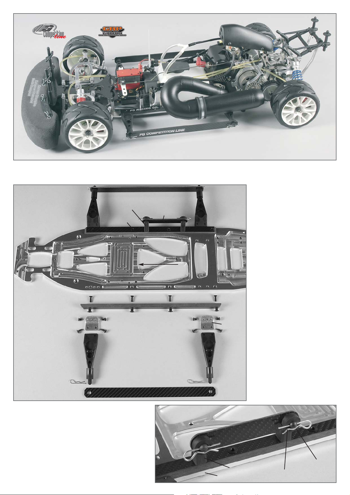
Baustufe 1: Chassisaufbau, Karosseriehalter, Akkuhalter
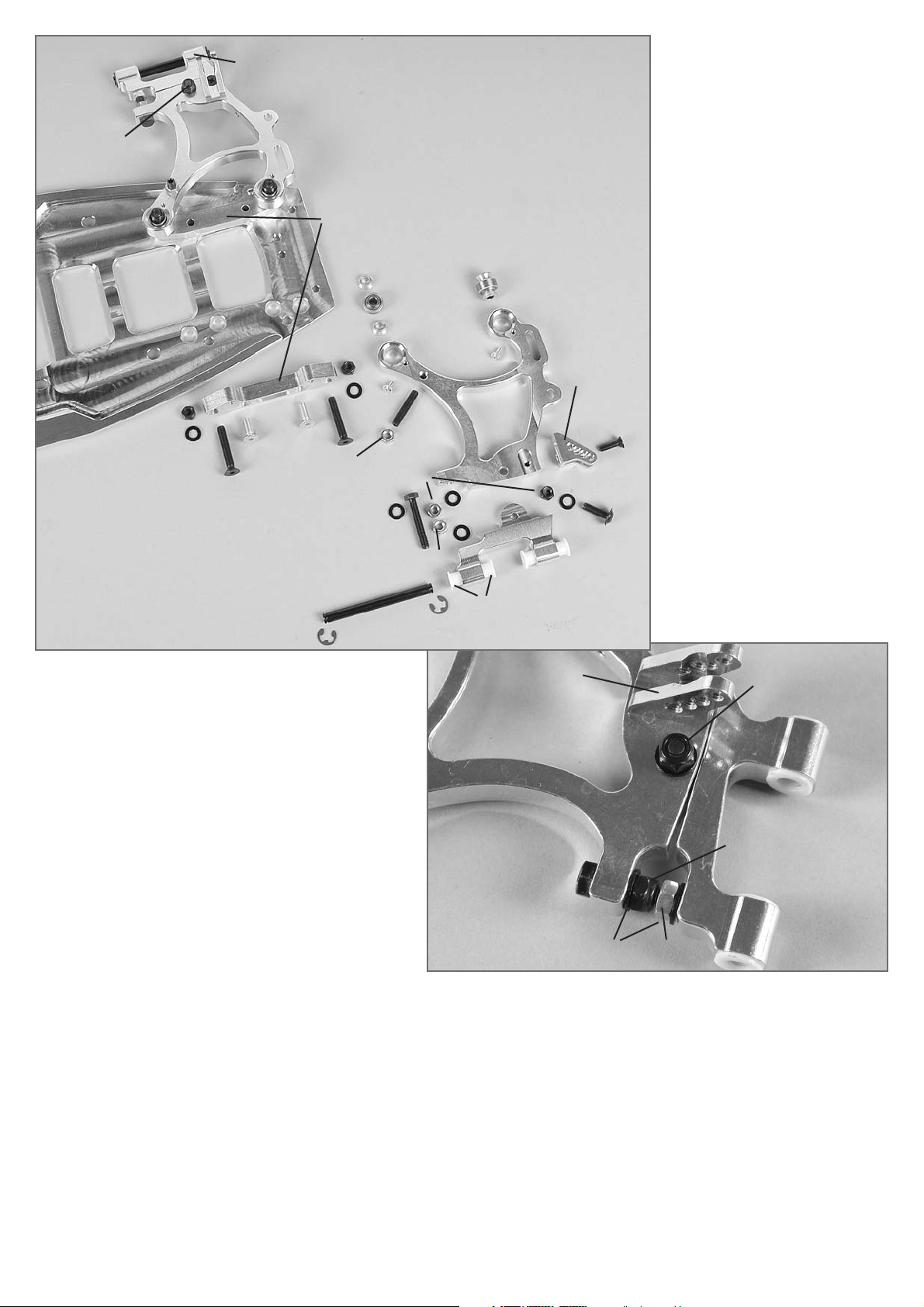
Baustufe 2: Querlenker hinten unten
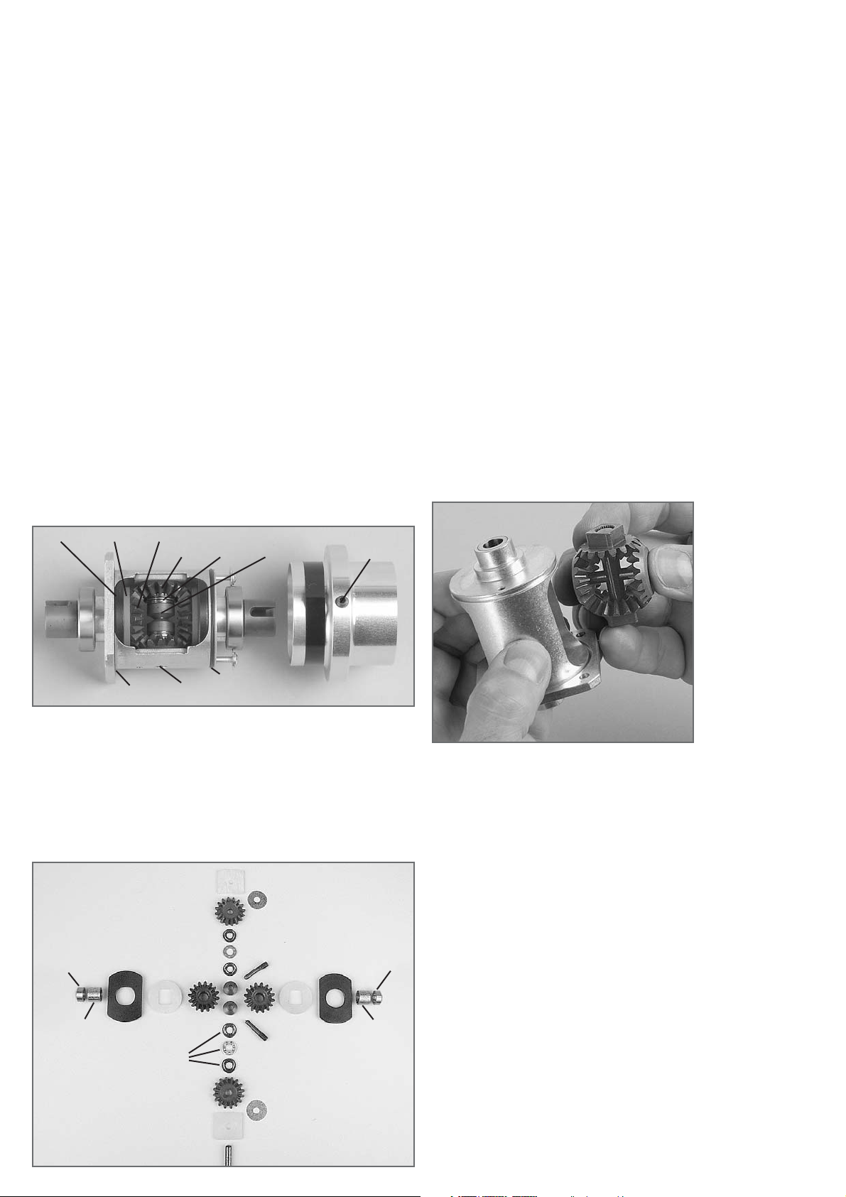
Baustufe 3: Differentialgetriebe
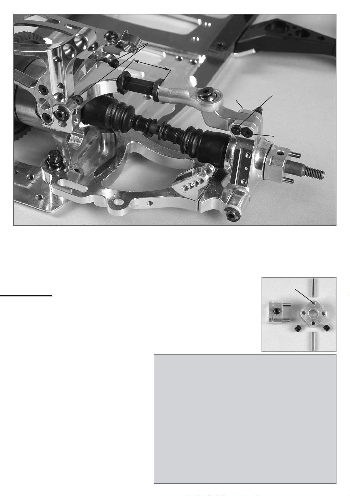
Baustufe 4,5,6: Hinterachse
Baustufe 7: Stoßdämpfer
Baustufe 8,9,10,10a,10b: Hinterachse, Karosseriehalter hinten
Baustufe 11,11a,12,13,14,14a: Motor, Luftfilter, Getriebe,Tank
Baustufe 15,16,17,17a: Vorderachse, Stabilisator vorne
Baustufe 18,19,19a: Servo-Saver, Spurstangen
Baustufe 20,21,22,23,24a: Servo-Empfängermontage, Gasgestänge
Baustufe 25-29: Tuning-Scheibenbremse vorne und hinten
Baustufe 30-33: FG Magura hydr. Bremsanlage
Baustufe 34,35: Schalldämpfermontage
Baustufe 36,37: Frontrammer
The handling with fuels requires circumspective and
careful handling. Imperatively observe the security ad-
vices.
- Refuel only if the engine is switched off!
- Take off the body.
- Thoroughly clean the area around the fuels nipple.
- Remove the fuel filler cap and carefully fill in the fuel mixture.
- Smoking or any kind of open fire is not admitted.
- Fuels might contain solvent-like substances. Avoid contact with skin and
eyes. Wear gloves for refueling. Do not inhale fuel vapors.
- Do not spill any fuel. If you have spilled fuel immediately clean the engine
and the model.
- Make sure that no fuel will get into the soils (environmental protection). Use
an appropriate mat.
- Do not refuel in enclosed rooms. Fuel vapors accumulate at the soil (risk of
explosion).
- Transport and store fuels only in admitted and labeled canisters. Keep fuel
out of the range of children.
- The operator is responsible for any damages caused to third persons in the
operating range of the model, respectively of the engine, if they are injured
or in case of property damage.
- The model must only be passed on to persons who are familiar with this
model and its operation, always provide the operating manual.
- Persons with implanted heart pacemakers must not work on running engines
and on live parts of the ignition system when the engine is being started.
- The engine must neither be started nor operated in enclosed rooms (without
sufficient ventilation).
- When starting the engine, avoid inhaling the exhausts.
- The model must neither be started nor operated without air filter or without
exhaust system.
- Before every start perform a functional check of the safety-relevant parts.
- The throttle rods must always return automatically to the idle position.
- Any cleaning, maintenance and repair works must only be performed with the
engine being switched off. The engine and silencers are getting very hot. In
particular do not touch the silencer.
Comments regarding the construction manual:
Before starting the assembly please see through this construction manual.
This way you will get an overview of the whole execution.
Please check by means of the parts or bag list if the construction kit is com-
plete and also check the weight of the individual bags for the positions. Only
this way you may be sure that all parts which you need for the assembly are
available. If a part is missing, please immediately contact your specialized
dealer.
Table of contents
Position 1: Chassis construction, body mount, battery holder
Position 2: Rear lower wishbone
Position 3: Differential gear
Position 4,5,6: Rear axle
Position 7: Shock absorber
Position 8,9,10,10a, 10b: Rear axle, rear body mount
Position 11,11a,12,13,14,14a: Engine, air filter, gear, tank
Position 15,16,17,17a: Front axle, front stabilizer
Position 18,19,19a: Servo saver, track rods
Position 20,21,22,23,24a: Servo receiver mounting, Throttle rods
Position 25-29: Front and rear tuning disk brake
Position 30-33: Hydraulic brake set FG Magura
Position 34,35: Tuning pipe mounting
Position 36,37: Front bumper

1. Alu-Karosseriehalter mit den M4x8
Senk-Schrauben am Chassis befe-
stigen.
2. Die Kunststoffhalter für die Akku-
Haltestrebe auf die rechte (in Fahrt-
richtung) CFK Chassisversteifung
mittels M4x16 Senk-Schrauben
montieren. CFK Chassisversteifun-
gen mit M4x14 Senk-Schrauben
und den Einpress-muttern
(Einpressmuttern von oben) auf das
Chassis schrauben.
3. Kunststoff-Karosseriehalter mit den
4,2x13 Senk-Schrauben an den
Alu-Karosseriehaltern befestigen.
4. Kohlefaser-Seitenschutzleisten auf
die Karosseriehalter stecken.
Tipp: Durch Weglassen der mittleren 2
Einpressmuttern je Seite kann die
Flexibilität des Chassis beeinflusst
werden (Chassis wird weicher).
Alle metrischen Schrauben sind mit Schraubensicherungslack zu sichern.
All metric screws need to be secured with thread lock fluid.
Baustufe 1
Teile sind in
Beutel A,A1
CFK- Chassis-
versteifung
Einpressmutter
Karosserie-
klammer
M4x8
Schraube/
Screw
M4x14
Schraube/Screw
Alu-Karos-
seriehalter
Kunststoff-
Karosseriehalter
4,2x13
Schraube/Screw
Kohlefaser-Seiten-
schutzleisten
Kunststoffhalter
Plastic body mount
M4x16
Dämpfungsgummi
Dampening rubber
Karosserieklammer
Body clip
CFK-Akkuhaltestrebe
CFK-Akkuhaltestrebe
Fahrtrichtung
1. Fix the alloy body mount on the chassis using the M4x8
countersunk screws.
2. Mount the plastic mount for the battery holder brace on
the right (in direction of motion) CFK chassis stiffening by
means of M4x16 countersunk screws. Screw the CFK
chassis stiffenings with M4x14 countersunk screws and
insert nuts (insert nuts from the top) on the chassis.
3. Fix the plastic body mount with the 4.2x13 countersunk
screws on the alloy body mounts.
4. Put the carbon fiber side guard strips on the body mounts.
Tip: By omitting the 2 center insert nuts on each side you can
influence the flexibility of the chassis (chassis becomes more
smooth).
Direction of motion
CFK battery holder brace
Position 1
The parts are in
the bags A, A1
CFK chassis
stiffening
Insert nut
Einpressmutter
Insert nut
Alloy body
mount
Kunststoffhalter
Plastic mount
Body clip
Plastic body mount
Carbon fiber side
guard strips
CFK battery holder brace
World Champion 2007
European Champion 2007
German Champion 2007

1073/5
Querlenker hint. rechts/
Rear wishbone right
1072/5
Querlenker hint. links/
Rear wishbone left
1072/5
Querlenker hint. links/
Rear wishbone left
1073/1
Schwenkteil hinten
rechts/Rear lower
swivel part right
Hinterachse
Sicherungsscheibe/
Retaining washer Ø 5
Kegelscheibe/
Taper disk
M3x6
Stopp-Mutter/
Stop nut M5
Stopp-Mutter/
Stop nut M5
Stopp-Mutter/
Stop nut M5
Mutter/
Nut M5
Mutter/
Nut M5
Scheibe/
Disk Ø 5,3
Schraube/Screw
M5x30
Schraube/
Screw M5x16
Schraube/
Screw M5x16
Schraube/
Screw M5x16
Scheibe/
Disk Ø 5,3
Scheibe/
Disk Ø 5,3
Gleitbuchse
Bund-Gleitbuchse/
Collar guide bush
Kugelbüchse/
Ball-type
nipple
M4x14
Schraube/
Screw
Alu-Hinterachs-
unterlage
Querlenkerstift/
Wishbone pin 6x65mm
1072/1
Schwenkteil
hint. links/Rear
swivel part left
1072/1
Schwenkteil
hint. links/Rear
swivel part left
Stoßdämpfer-
befestigung
Stoßdämpferbefestigung
Damper mount
Baustufe 2
Teile sind
in Beutel B
M5x30
Gewindestift
Headless pin
M5x25
M5x30 Truck
M5x14
M5x20 Truck
Position 2
The parts are
in the bag B
Rear axle
Alloy support
for rear axle
Damper
mount
Guide bush
Mutter M5
Stopp-
Mutter M5
Scheibe/Disk
Ø 5,3
Schraube/
Screw
M5x30
Stop nut M5
Nut M5
1. Die Kugelbüchsen in die Querlenker
einpressen. Die eingepressten Ku-
gelbüchsen mit den M3x6 Linsen-
Flachkopfschrauben sichern.
2. Bund-Gleitbuchsen nach Abb. in
die Schwenkteile eindrücken.
3. Schwenkteil mit M5x16 Linsen-
Flachkopfschraube (von unten),
Ø 5,3 Scheibe und M5 Mutter (von
oben) nach Abb. am Querlenker be-
festigen, M5 Mutter nur leicht an-
ziehen. M5x30 Sechskantschraube,
Ø 5,3 Scheiben und M5 Muttern
nach Abb. montieren.
4. Alu-Stoßdämpferbefestigung mit
M4x14 Senk-Schraube am Quer-
lenker befestigen.
5. M5x25 (M5x30 bei Truck)
Gewindestift und M5 Mutter nach
Abb. in den Querlenker schrauben.
6. Vormontierten Querlenker mit M5x30
Senk-Schrauben, Ø 5,3 Scheiben und
M5 Muttern auf die Hinterachsunter-
lage schrauben. Dabei je eine Ke-
gelscheibe wie abgebildet ober- und
unterhalb der Kugelbüchse mitmon-
tieren.
7. Komplette Einheit mit M5x14
(M5x20 bei Truck) Senk-Schrauben
auf dem Chassis befestigen.
Tipp: Hinterachsunterlagen links und
rechts sind unterschiedlich. Vor der
Montage bitte darauf achten, dass die
Bohrungen mit dem Chassis überein-
stimmen. Kegelscheibe immer mit der
dünnen Seite zur Kugelbüchse montie-
ren.
1. Mould the ball-type nipples in the wishbone. Secure the
moulded in ball-type nipples with M3x6 lenticular flange head
screw.
2. Push the flange guide bushes into the swivel part according
to the illustration.
3. Fix the swivel part with M5x16 lenticular flange head screw
(from the bottom), Ø 5.3 disk and M5 nut (from the top) on
the wishbone according to the illustration, tighten screw only
slightly. Mount M5x30 hexagon head screw, Ø 5.3 disks and
M5 nuts according to the illustration.
4. Fix the alloy shock absorber fastening with M4x14 counter-
sunk screw on the wishbone.
5. Screw M5x25 (M5x30 for Truck) thread pin and M5 nut in the
wishbone according to the illustration.
6. Screw the premounted wishbone with M5x30 countersunk
screws, Ø 5.3 disks and M5 nuts on the support for rear axle.
In doing so, mount one taper disk each above and below the
ball-type nipples as illustrated.
7. Fix the complete unit with M5x14 (M5x20 for Truck) counter-
sunk screws on the chassis.
Tip: The supports for rear axle on the left and on the right are dif-
ferent. Before assembling, please make sure that the borings
match the chassis. Always mount the taper disk with the thin
side towards the ball-type nipple.

6067 8491 8496/1
Alu-Differentialgetriebe
4-fach selbstsperrend
Alloy differential gear
4-fold self-locking
Alu-Differentialgetriebe
4-fach selbstsperrend
8496/2
8487
6917/8
8486/2
8500/1 8500/3
8500/2
8493/5
O-Ring groß/big O-Ring
klein/small
6068
6067
6067
8491
8491
8496/1
8500/3
8500/2 8500/2
8496/2
8501/2
8501/2
8500/1 8500/1 8600/58600/5
8499/1 8499/1
6743
6743
8496/3
6068
8490
Montage
Kugellager 8493/05 auf das Alu-Differentialgehäuse aufdrücken.
Nach Abb. die Diff.-Kegelzahnräder 8500/3 und 6067 mit den Reibscheiben
8500/2 und den Anlaufplatten (im Paket) in das Alu-Differentialgehäuse 8486
bzw. 8486/2 einführen. Jetzt beide Diff.-Antriebsachsen 6069/1 bzw. 6069/2
und die Kegelrad- achse 6068 bzw. 8490 eindrücken. Die Bohrungen des
Diff.-Gehäuses müssen mit den Bohrungen der Diff.-Kegelzahnräder fluchten.
Bei einem Versatz der Bohrungen muss das komplette Zahnradpaket aus
dem Diff.-Gehäuse entnommen und die Diff.-Kegelzahnräder um 1 Zahn zu-
einander versetzt werden. Danach das komplette Paket wieder in das Diff.-
Gehäuse einführen. Bei Verwendung des FG Montagewerkzeuges Best.-Nr.
8505 wird das Einsetzen der Diff.-Kegelzahnräder bzw. des kompletten Pa-
ketes wesentlich erleichert.
4-fach selbstsperrend: Kegelradachse etwas herausdrücken und eine An-
laufscheibe zwischen Kegelzahnrad B und Alu-Differentialgehäuse schieben.
Zweite Anlaufscheibe auf die gleiche Weise montieren.
Jetzt die Diff.-Kegelradachse 6068 bzw. 8490 etwa zur Hälfte herausdrücken.
Nachfolgend 1x Axiallager 8491, danach beide Druckscheiben 8496/1 mit
Konus gegeneinander zur Mitte und zuletzt das zweite Axiallager 8491 mon-
tieren. Diff.-Kegelradachse 8490 wieder vollständig in das Diff.-Gehäuse 8486
eindrücken. Diff.-Antriebsachsen 6069/1 bzw. 6069/2 drehen und prüfen, ob
das Diff.-Getriebe leichtgängig läuft. Zuviel Zahnradspiel kann mit beilie-
genden Passscheiben 6743 (5x17x0,1) ausgeglichen werden.
Etwa eine halbe Tube FG Klüber Allzweckfett 6501 auf die Diff.-Kegelzahn-
räder geben und die O-Ringe 8489 in die vorgesehene Nut des Alu-Diff.-Ge-
häuse einlegen.
Schrumpfschlauch 8496/3 nach Abb. auf die Differentialhülse mittels Haar-
föhn aufschrumpfen.
Jetzt das Stahl-Zahnrad groß 48 Zähne mittels den Senkschrauben M4x8
montieren. Alu-Hülse 8487 nach Abb. auf das Diff.-Gehäuse aufschieben.
Danach die Einstellschrauben 8496/2 in die M5 Bohrungen der Alu-Hülse ein-
drehen, bis diese zwischen den Druckscheiben 8496/1 anliegen, etwas Schrau-
bensicherungslack verwenden. Alu-Hülse mittels den M3 Schrauben fixie-
ren.
Erläuterung
Die Sperrwirkung bei einem selbstsperrenden Differentialgetriebe entsteht
durch das entstehende Drehmoment, in dem die Kegelzahnräder 8500/3 bzw.
6067 auf die Reibscheibe bzw. Anlaufscheibe drücken und durch erhöhte
Reibung abgebremst werden. Zusätzlich können diese Differentialgetriebe
durch die Einstellschrauben in der Alu-Hülse noch mechanisch gesperrt wer-
den, indem diese im Uhrzeigersinn eingeschraubt werden. Um das Differen-
tial mechanisch zu sperren, beide Einstellschrauben gleichmäßig im Uhrzei-
gersinn eindrehen. Durch gleichmäßiges Herausdrehen (gegen den Uhrzei-
gersinn) erhalten Sie weniger Sperrwirkung.
Ersatzteile/ Spare parts
6067 Diff.-Kegelzahnrad B, 2St./ Differential gearwheel B, 2pcs.
6068 Diff.-Kegelradachse, 1St./ Bevel differential gear axle, 1pce.
6717/8 Linsen-Flanschkopfschr. M3x8, 5St./ Lenticular flange head
screw M3x8, 5pcs.
6743 Passscheiben 5x17x0,1, 10St./ Shim rings 5x17x0,1, 10pcs.
8486 Alu-Differentialgehäuse, 1St./ Alloy differential housing, 1pce.
8486/2 Alu-Differentialgeh. 4-fach selbstsp., 1St./ Alloy diff.housing,four
fold, self-lock., 1pce.
8487 Alu-Hülse, 1St./ Alloy socket, 1pce.
8489 O-Ringe, 2St./ O-rings, 2pcs.
8490 Kegelradachse, 1St./ Bevel wheel axle ,1pce.
8491 Axialkugellager 5x12x4, 1St./ Thrust ball bearing 5x12x4, 1pce.
8493 Kugellager 15x28x7, 2St./ Ball bearing 15x28x7, 2pcs.
8496/1 Druckscheibe, 2St./ Pressure disk, 2pcs.
8496/2 Einstellschraube, 2St./ Adjusting screw, 2pcs.
8496/3 Schrumpfschlauch, 2St./ Heat shrink tube, 2pcs.
8499/1 Nadellager für Diff., 2St./ Needle bearing for differential, 2pcs.
8600/5 Bronzebuchse 8x12x5, 2St./ Bronze bushes 8x12x5, 2pcs.
8500/1 Anlaufplatte, 2St./ Stop plate, 2pcs.
8500/2 Reibscheibe, 2St./ Friction disk, 2pcs.
8500/3 Diff-Kegelzahnr. selbstsperr., 2St./ Diff. gearwh., self-lock., 2pcs.
8501/2 Anlaufscheibe, 2St./ Stop disk, 2pcs.
Bei Verwendung des
FG Montagewerkzeu-
ges Best.-Nr. 8505
wird das Einsetzen
der Diff.-Kegelzahn-
räder bzw. des kom-
pletten Paketes we-
sentlich erleichert.
Mounting
Press ball bearing 8493 on the alloy diff. housing.
Insert the diff. bevel gear wheels 8500/3 and 6067 together with the friction
disks 8500/2 and the stop plates (in the set) into the alloy differential housing
8486 or 8486/2 as shown on the picture. Now press in both differential driv-
ing axles 6069/1 or 6069/2 and also the bevel wheel axles 8490 or 6068. The
borings of the differential housing must be in true alignment with the borings
of the differential bevel gear wheels. If you notice a misalignment of the bor-
ings, take the complete package out of the differential housing and replace
the diff. bevel gear wheels one tooth offset. Then mount the complete pack-
age back in the diff. housing.
Quadruple self-locking: Squeeze out the bevel wheel axle a little and push
a stop disk between bevel gear wheel B and alloy diff. housing. Mount the sec-
ond stop disk in the same way.
Now pull out the differential bevel wheel axle 6068/8490 half. Then mount
one thrust ball bearing 8491, afterwards both pressure disks 8496/1 with the
cones opposed to the middle and last the second thrust ball bearing 8491.
Press the differential bevel wheel axle 8490 completely into the differential
housing 8486 again. Turn the differential driving axles 6069/1 or 6069/2 and
check if the differential gear runs easy. Too much tooth clearance can be bal-
anced with the enclosed shim rings 6743 (5x17x0,1).
Apply about half a tube of FG Klüber grease 6501 on the differential bevel gear
wheels and insert the o-rings 8489 in the provided groove of the alloy differ-
ential housing 8486.
Shrink the shrinkdown plastic tubing 8496/3 on to the differential socket with
a hair dryer.
Now mount the big steel gearwheel 48 teeth with the countersunk screws
M4x8. Push the alloy socket 8487 on to the differential housing as shown on
the picture. At the same time screw the adjusting screws 8496/2 into the M5
borings of the alloy socket until they lay firm between the pressure disks
8496/1, use some securing lacquer. Fix the alloy socket with the M3 screws.
Explanation
The valve effect of a self-locking differential gear is caused by the torque
which is developed when the bevel gear wheels 8500/3 or 6067 press on the
friction disk or stop plate and the higher friction causes a brake effect. Addi-
tional these differential gears can be locked mechanically through adjusting
screws in the alloy socket if you screw these in in clockwise direction. To lock
this differential mechanically, turn in both adjusting screw symmetrically in
clockwise direction. You achieve less valve effect if you unscrew them anti-
clockwise.
Inserting of the diff.
bevel gear wheels or
of the complete
package becomes
much easier if you
use the FG mounting
tool 8505.

Baustufe 5
Teile sind
in Beutel C
Hinterachse
Gewindestift/
Headless pin
M5x5
Schutzbalg
Kugel-
antriebswelle
Kugelan-
triebsachse
Gewindestift/
Headless pin
M4x4
Gewindestift/
Headless pin
M3x3
Sicherungs-
scheibe/Retain-
ing washer Ø3,2
Mutter/Nut M4
Gleitbuchsen
Schraube/
Screw
M4x25
Schraube/Screw
M5x20
Alu-
Kugelgelenk
Einstellschraube/Ad-
justing screw 53mm
Muttern/Nuts R/L
Sicherungsscheibe/
Retaining washer Ø5
Sicherungs-
scheibe Ø5
Querlenker-
stift 6x65mm
Querlenkerstift 6x65
Wishbone pin 6x65
Einstellclipse
Achsschenkel-
stift
Baustufe 4
Teile sind in
Beutel C Hinterachse
Getriebeplatine
Abstützung Motor-
Getriebeplatine
M4x12
Schraube/
Screw
Alu-Dämpfer-
platine
Alu-Hinter-
achsbock M4x16
Schraube/Screw
M4x8
Schraube/Screw
M4x16
Schraube/Screw M4x8
M4x20 Truck
Scheibe/Disk Ø4,3
1. Stahl-Zahnrad 48 Zähne nach Abb.
auf das Diff.-Gehäuse aufschieben
und mit den Senk-Schrauben M4x8
festschrauben.
2. Alu-Hinterachsböcke nach Baustufe 4
auf die Kugellager des Differential-
getriebes aufdrücken und mit der
Alu-Dämpferplatine mit M4x12 Zylin-
der-Schrauben sowie die Getriebe-
platine mit M4x8 Linsen-Schrauben
(bei Truck mit M4x20 und Alu-
Hinterachsunterlage) und Ø 4,3
Scheiben montieren.
3. Abstützung Motor-Getriebeplatine
mit einer M4x8 (M4x20 bei Truck)
Linsen-Schraube (und Alu-Distanz
bei Truck) und 4,3 Scheibe nach
Abb. montieren.
4. Komplette Einheit mit M4x16 Senk-
Schrauben zuerst auf die Alu-
Hinterachsunterlagen, dann auf
dem Chassis montieren.
Schraube/Screw
M4x8
Scheibe/Disk
Ø4,3
1. Gleitbuchsen in den Alu-Querlenker hinten oben einpressen.
2. Sechskantmutter M8 Linksgewinde auf die Einstellschraube 39mm drehen. Diese in den Alu-
Querlenker eindrehen, danach Sechskantmutter M8 Rechtsgewinde und das Alu-Kugelgelenk auf
das Rechtsgewinde der Einstellschraube so aufdrehen, dass der Sechskant der Einstellschraube mit-
tig sitzt
3. Alu-Querlenker nach Abb. mit dem Querlenkerstift Ø6x65mm montieren und mit Ø5
Sicherungsscheiben befestigen.
4. Die Querlenkerstifte mit Gewindestift M4x4 klemmen.
5. Kugel-Antriebsachse in die mit Kugellagern bestückten Achsschenkel drücken und Felgen-
Vierkantmitnehmer mit dem Absatz zum Lager zeigend mit M5x5 Gewindestiften befestigen.
6. Kugel-Antriebsset nach beiliegender Anleitung montieren.
7. Alu-Achsschenkel und Quer-
lenkerstift 6x65 nach Abb.
einbauen und mit M3x3 Ge-
windestiften und Ø 5 Sicher-
ungsscheiben befestigen.
8. Die Distanzscheiben aus
Gummi in die runde Ausspar-
ung der Kugelantriebsachse
und Kugel-Diff.-Achse ein-
drücken. Schutzbalg nach
Abb. montieren.
9. Kugeln einfetten und in die
Kugelantriebswelle eindrücken.
Kugelantrieb nach beiliegen-
der Anleitung montieren.
Alu-Dist. Truck
Stahl-Zahnrad 48 Z.
Steel gear 48 teeth
1. Push steel gearwheel 48 teeth on
the diff. housing and screw it tight
with the countersunk screws M4x8.
2. Press on the alloy rear axle mounts
on the ball bearings of the differen-
tial gear according to the position 4
and mount them with the alloy dam-
per plate with M4x12 socket cap
screws as well as the gear plate
with M4x8 pan-head screws (M4x20
and alloy rear axle base for Trucks)
and Ø 4.3 disks.
3. Mount the support engine gear
plate with a M4x8 (M4x20 for Truck)
pan-head screw (and alloy distance
for Truck) and 4.3 disk according to
the illustration.
4. First mount the complete unit with
M4x16 countersunk screws on the
alloy supports for rear axle, then on
the chassis.
Position 4
The parts are
in bag C
Gear plate
Support engine-
gear plate
Alloy
damper
plate
Rear axle
Alloy rear
axle mount
Position 5
The parts are
in bag C
Rear axle
Ball driving
axle
Protecting
expansion bend
Ball driving
shaft
Upright pin
Guide bushes
Wishbone
pin 6x65mm
Adjusting clips
Alloy ball-
and-socket
joint

1. Press the guide bush in the alloy wishbone at the
rear top.
2. Screw the hexagon socket nut M8 with left-han-
ded thread on the adjusting screw 39mm. Turn it
in the alloy wishbone, then unscrew the hexagon
nut M8 with right-handed thread and the alloy
ball-and-socket joint on the right-handed screw
of the adjusting screw in a way that the hexagon
of the adjusting screw is centered.
3. Mount the alloy wishbone with the wishbone pin
Ø6x65mm according to the illustration and fix it
with Ø5 retaining washers.
4. Clamp the wishbone pins with the headless pin
M4x4.
5. Press the ball driving axle into the uprights
equipped with ball bearings and fix the square
wheel driver with its offset towards the bearing
using M5x5 headless pins.
6. Mount the ball driving set according to the
enclosed instruction.
7. Fix the alloy upright and the wishbone pin
according to the illustration and fix them using
M3x3 headless pins and Ø 5 retaining washers.
8. Push the distance disks made off rubber in the
round slot of the ball driving axle and the ball
diff. axle. Mount the protecting expansion bend
according to the illustration.
9. Grease the balls and inpress them into the ball
driving shaft. Mount the ball driving according to
the enclosed instruction.
Stifte in das Sack-
loch eindrücken.
Impress the pins
into the pocket
hole.
Schraube/
Screw
M5x20
Schraube/Screw
M4x25
29mm
Querlenker mittels Einstellclipse
ausdistanzieren./ Align the
wishbone with adjusting clips.
Achsschenkelverlängerung/
Upright lengthening
Hinterachse
Sicherungs-
scheibe Ø 3,2
Achsschenkelstift
Stopp-Mutter/
Stop nut M4
Baustufe 6
Teile sind
in Beutel C
Position 6
The parts are
in bag C
Upright pin
Rear axle
Retaining
washer Ø 3.2
1. Alu-Achsschenkelverlängerung nach Abb. montieren und mit
Achsschenkelstift, Ø 3,2 Sicherungsscheibe, Senk-Schraube
M4x25 und M4 Stopp-Mutter befestigen.
2. Kugelgelenk mit Alu-Gelenkkugel mit Senk-Schraube M5x20 auf
die Achsschenkelverlängerung schrauben.
Tipp: Entsprechend der Einstellung der Vorspur muss der obere
Querlenker mittels den Einstellclipsen ausdistanziert werden.
1. Mount the alloy upright lengthening according to the illustration and
fix it with the upright pin, Ø 3.2 retaining washer, countersunk screw
M4x25 and M4 stop nut.
2. Screw the ball-and-socket joint with alloy joint ball using the coun-
tersunk screw M5x20 on the upright lengthening.
Tip: The upper wishbone needs to be aligned according to the setting
of the toe-in by means of adjusting clips.

1. Je 2 Führungen mit Bund in den Dämpferverschluss 04 oben einpressen,
Volumenausgleich in den Dämpferverschluss einlegen. O-Ringe in die
Verstellringe einlegen und auf das Stoßdämpfergehäuse schrauben (flache Seite
in Richtung Sechskant).
2. Je 1 Führung mit Bund in den Dämpferverschluss 04 unten mit dem Bund zum
Innengewinde zeigend einpressen.
3. Je 1 Führung mit Bund ins Stoßdämpfergehäuse mit dem Bund zum kleinen
Gewinde zeigend einpressen.
4. Dämpferkolben mit der kleineren Vertiefung zur Kolbenstange zeigend montieren
und mit Scheibe 3,2mm und Stopp-Mutter M3 festziehen.
5. Kolbenstange nun in das Stoßdämpfergehäuse stecken in folgender
Reihenfolge: O-Ring/ Führung o. Bund/ O-Ring, die leicht eingeölt sein sollten,
dann auf die Kolbenstange schieben.
6. Stoßdämpferverschluss 04 unten auf die Kolbenstange schieben und mit dem
Stoßdämpfergehäuse verschrauben. Dämpferbefestigung kurz auf das Gewinde
der Kolbenstange schrauben, bis kein Gewinde mehr zu sehen ist. Die
Kolbenstange darf hierbei nicht beschädigt werden. Wir empfehlen deshalb die
Haltezange Best.-Nr. 6854 zu verwenden.
7. Stoßdämpfer bis zur Markierung mit Öl befüllen.
8. Kolbenstange mehrmals langsam ins Stoßdämpfergehäuse schieben und her-
ausziehen, damit die Luftblasen im Öl nach oben steigen. Wenn keine
Luftblasen mehr aufsteigen, Dämpferverschluss oben ca. 2 Umdrehungen auf-
schrauben. Kolbenstange langsam ins Stoßdämpfergehäuse schieben, bis ca.
5mm von der Kolbenstange noch zu sehen sind, nun den Dämpferverschluss
oben festschrauben.
9. Das überschüssige Öl tritt an der Querbohrung des Dämpferverschlusses aus.
10.Nun die blauen Federn auf die hinteren Stoßdämpfer montieren und mit dem
Federteller sichern. Bei den vorderen Stoßdämpfern ist mit den roten Federn
gleich zu verfahren.
Dämpferver-
schluss oben
Dämpferverschluss
unten/Lower shock
absorber seal
Dämpferbe-
festigung kurz
Stoßdämpfer-
gehäuse
Federteller
Führung
mit Bund
Führung mit
Bund/Guiding
with waistband
Volumenausgleich
Verstellring
O-Ring
O-Ring
Mutter/Nut M3
Scheibe/Disk
Ø3,2
O-Ring
O-Ring
Führung o.
Bund/Guiding
w/o waistband
Kolben/
Piston
Kolbenstange kurz
Baustufe 7
Teile sind
in Beutel D
1. Mould 2 guides each with collar into the shock plug 04 at the top, insert the volume compensation into the shock absorber seal. Insert O-rings
into the adjustable rings and screw them on the shock absorber housing (flat side in direction of the hexagon).
2. Mould 1 guide with collar each in the shock absorber seal 04 at the bottom with the collar towards the internal thread.
3. Mould 1 guide with collar each into the shock absorber housing with the collar showing towards the smaller thread. Mount the securing rings
3.2mm in the first chamfer of the short piston rod.
4. Mount the shock piston with the recess towards the securing ring and fix it with disk Ø 3.2mm and stop nut M3.
5. Now put the piston shaft in the shock absorber housing in the following order: O-ring/ guiding w/o collar/ O-ring, which should be slightly
oiled, then push it on the piston shaft.
6. Push the shock absorber locking 04 bottom on the piston shaft and screw it with the shock absorber housing. Screw the shock fastening short
on the thread of the piston shaft until you cannot see anymore of the thread. Make sure the piston rod is not damaged, we therefore recom-
mend to use the pliers Item N°. 6854.
7. Fill the shock absorber with oil up to the marking.
8. Push the piston shaft several times slowly into the shock absorber housing and pull it out again, in a way that the air bubbles in the oil can rise.
If no more air bubbles are rising unscrew the shock absorber seal top by about 2 turns. Shift the piston shaft slowly into the shock absorber
housing until you can only see about 5mm of the piston shaft, now firmly bolt the shock absorber seal.
9. The excessive oil will escape at the cross hole of the shock absorber seal.
10.Now mount the blue springs on the rear shock absorbers and secure them with the spring plate. Proceed in the same way with the front shock
absorbers using the red springs.
Position 7
The parts are
in bag D
Guiding
with
waistband
Upper shock
absorber seal
Volume compensation
Shock absorb.
housing
Spring plate
Piston shaft short
Shock fastening
short

Schrauben/Screws
4,2x22
Schraube/Screw
4,2x9,5
Schraube/Screw
2,9x9,5
Schraube/Screw
4,2x13
Dämpferplatine/
Shock absorber plate
Schraube/Screw M4x14
Schraube/
Screw M4x14
Karosseriestütze/
Ext. rear body mount
Karosserieauflage/
Body mount
Baustufe 8
Teile sind
in Beutel E
1. Karosseriestütze mit M4x14 Zylinder-Schrauben an Dämpferplatine
montieren. Für die Kunststoffteile sind die Blechschrauben 4,2x22/
4,2x9,5/ 2,9x9,5 sowie 4,2x13 zu verwenden. Kunststoffteile der
Heckstütze mit Ø 2mm Bohrer vorbohren, um die Montage der
2,9x9,5 Blechschrauben zu erleichtern.
2. Karosserieauflage zu einem späteren Zeitpunkt je nach Karosserietyp
in der Höhe einstellen.
3. Vormontierte hintere Stoßdämpfer mit M4x25 Senk-Schrauben und
M4 Stopp-Muttern, unten M4x14 Linsen-Schrauben befestigen.
1. Mount the body support on the shock absorber plate using M4x14
socket cap screws. Use the sheet metal screws 4.2x22/ 4.2x9.5/
2.9x9.5 as well as 4.2x13 for the plastic parts. Predrill plastic parts of
the rear support with Ø 2mm drill in order to facilitate the assembly of
the 2.9x9.5 sheet metal screws.
2. Adjust the height of the body mount front depending on the body
type later.
3. Fix the premounted rear shock absorbers using the M4x25 counter-
sunk screws and M4 stop nuts, at the bottomM4x14 pan-head
screws.
Position 8
The parts are
in bag E
Baustufe 9
Teile sind
in Beutel J
Entlüftungsnippel
Stabi.-Draht
mit Kugelpfanne
Stabi.-Draht
mit Kugelführung
Klemmbolzen
M5 bzw. M6
Scheibe
5,3 o. 6,4
Stopp-Mutter
M5 oder M6
Gewinde-
stift M5x5
Baustufe/
Position 9a
Klemm-
bolzen M6 Klemm-
bolzen M5
Kugelführung
Kugelpfanne
1. Entlüftungsnippel ins Chassis schrauben.
2. Je eine M5 bzw. M6 Mutter auf die Klemmbolzen
aufschrauben. Danach eine Scheibe 5,3 bzw.6,3
ansetzen und die Klemmbolzen nach Abb. in den
Querlenker montieren.
3. Von unten eine Scheibe 5,3/ 6,4 ansetzen und die
M5 bzw. M6 Stopp-Mutter auf den Klemmbolzen-
schrauben – Muttern noch nicht festziehen.
4. Den Stabi.-Draht mit Kugelführung in die Klemm-
bolzen drücken und mit den M5x5 Gewindestiften
klemmen. Die Kugelführung muss sich genau in
der Mitte des Chassis befinden. Die Muttern nun
festschrauben.
5. Mit dem Stabi.-Draht der Kugelpfanne genauso
verfahren. Die Kugelführung nicht zu tief in die
Kugelpfanne montieren, so dass beim Ausfedern
bzw. Einfedern die Kugelführung nicht auf den
Rand der Kugelpfanne drückt.
1. Screw the vent nipple in the chassis.
2. Screw each one M5 or M6 nut on the clamp bolt. Then affix a disk 5.3 or.6.3 and mount the
clamp bolts on the wishbone according to the illustration.
3. Affix a disk 5.3/ 6.4 from the bottom and screw the M5 or M6 stop nut on the clamp bolt –
do not fasten the nuts yet.
4. Press the fixing wire with ball bearing in the clamp bolt and clamp it using the M5x5 headless
pins. The ball guide needs to be positioned exactly in the center of the chassis.
5. Now firmly tighten the nuts. Proceed in the same way with the fixing wire of the ball guide.
There must be enough clearance between the ball guide and the ball socket in a way that the
vehicle does not block when deflecting and rebounding.
Position9
The parts are
in the bag J Ball bearing traveler
Ball work pan
Fixing wire
with ball work pan Vent nipple Clamp bolt
M6
Clamp bolt
M5
Fixing wire with
ball bearing
traveler
Headless
pin M5x5 Clamp bolt
M5 or M6
Disk
5,3 o. 6,4
Stop nut M5
or M6
Schraube/Screw M4x25
Mutter/ Nut M4

Schraube/Screw
2,9x22
Schraube/Screw
2,9x16
Karosseriebolzen/
Body bolt
Karosseriebolzen/
Body bolt
Karosserieklammer/
Body clip
Alu-Dämpferplatine
Alloy damper plate
Alu-Dämpferplatine
Alloy damper plate
Karosserieklammer/
Body clip
Abbildungen 10/ 10a/ 10b nur bei Renn-Trucks!
Entsprechend der verwendeten Renn-Truck Karosserie
Karosseriehalter an die Dämpferplatine montieren.
Karosseriehalter für Renn-Truck
Karosserie Best.-Nr. 3070 MAN-Truck
Body mount for Race Truck body
Item N°. 3070 MAN-Truck
Karosseriehalter für Renn-Truck
Karosserie Best.-Nr. 3049 CAT-Truck
Body mount for Truck Body
Item N°. 3049 CAT-Truck
Baustufe 10a
Teile sind
in Beutel E
Baustufe 10
Teile sind
in Beutel E
Position 10
The parts are
in bag E
Position 10a
The parts are
in bag E
Illustrations 10/ 10a/ 10b only for Race Trucks!
Mount the body mount on the shock mount according to the used
Race Truck body.

Karosserieauflage/
Rear body mount
Schraube/ Screw M4x14
Schrauben/Screws
4,2x22
Schraube/
Screw
4,2x9,5
Alu-Dämpferplatine
Alloy damper plate
Karosseriehalter für Renn-Truck Karosserie
Best.-Nr. 3053 MB-Truck 1834 und Best.-Nr. 3064 Atego-Truck
Body mount for Race Truck body
Item N°. 3053 MB-Truck 1834 and Item N°. 3064 Atego-Truck
Karosserieauflage zu einem späteren Zeitpunkt einstellen.
Adjust body mount later.
Baustufe 10b
Teile sind
in Beutel E
Position 10b
The parts are
in bag E

1. Krümmer und Dichtung an den Motor mit den
M5x16 Linsen-Schrauben nach Abb. montieren.
2. Die 4 Gewindestifte M5x20 mit
Schraubensicherungslack versehen und in das
Motorgehäuse eindrehen, bis diese noch ca.
9mm aus dem Gehäuse ragen.
3. Motorflansch mit der Ausfräsung zum Zylinder
zeigend auf das Gehäuse bzw. Gewindestifte
drücken und mit den M5 Stopp-Muttern befesti-
gen.
4. FG 4-Backen-Kupplung lt. beiliegender
Montageanleitung montieren.
5. FG Ansaug-Geräuschfilter lt. beiliegender
Montageanleitung montieren.
Gewindestift M4x6 mit Schraubensicherung bis zum Kontakt zur Federführung eindrehen. Durch
gleichmäßiges Eindrehen wird die Federkraft erhöht und die Kupplung greift später ein.
Screw the headless pin M4x6 with screw locks until it contacts the spring guide. By uniform screwing
the spring force will be increased and the clutch will cam in later on.
Baustufe 11
Teile sind
in Beutel G
Gewindestift
M5x20
Stopp-
Mutter M5
Krümmer
Ausfräsung
Motorflansch/
Engine flange
Kupplungs-
mitnehmer/
Clutch carrier
Kupplungsbacken
Kupplungsfeder
Kupplungsfeder
Deckscheibe
Schraube/
Screw
M6x35
Schraube/
Screw M5x16
Gewindestift/
Headless pin
M4x6
Schrauben
M3x5
Federführung
Federführung
FG Ansaug-Geräuschfilter
Baustufe 11a
Teile sind
in Beutel G
1. Mount the manifold and the gasket on the engine
using M5x16 pan-head screws according to the
illustration.
2. Provide the 4 headless pins M5x20 with thread-
lock fluid and screw them into the engine hou-
sing until they will only protrude the housing by
about 9mm.
3. Press the engine flange with the milling groove
directed towards the cylinder on the housing or
on the headless pins and fix them using the M5
stop nuts.
4. Mount the FG 4-block clutch according to the
enclosed assembly instruction.
5. Mount the FG inlet silencer according to the
enclosed assembly instruction.
FG inlet silencer
Manifold
Headless pin
M5x20
Stop nut M5
Clutch blocks
Spring guide
Clutch spring
Screws
M3x5
Cover disk
Position 11
The parts are
in bag G
Position 11a
The parts are
in bag G
Clutch spring
Spring guide

Schraube/Screw
M5x14
Schraube/
Screw
M5x14
Schraube/
Screw M5x12
Getriebeflansch-
Motorbock
Alu-Getriebeplatte/
Alloy gear plate
Alu-Getriebeplatte/
Alloy gear plate
Schraube/
Screw
M4x12
Schraube/Screw
M6x10
Schraube/
Screw
M6x10
Schraube/
Screw
M6x10
Schraube/
Screw
M6x10
Schraube/
Screw
M6x10
Schraube/
Screw
M6x10
Alu-Zahnradmitnehmer/
Alloy gear carrier
Motorbefestigungs-
Scheibe/ Engine
fastening disk
Scheibe/Disk
10x16x1
Scheiben/
Disks
10x16x1
Scheiben/
Disks
10x16x1
Scheiben/Disks
10x16x1
Kupplungsglocke/
Clutch bell
Stahl-Zahnrad16 Zähne/
Steel gearwheel 16 teeth
Stahl-Zahnrad16 Zähne/
Steel gearwheel 16 teeth
Stahl-Zahnrad/
Steel gearwheel
Stahl-Zahnrad/
Steel gearwheel
Kunststoff-Zahnrad/
Plastic gearwheel
Kunststoff-Zahnrad/
Plastic gearwheel
Getriebeachse
Distanzbuchse/
Distance bush 13x43
Gewindestift/
Headless pin M5x6
Gewindestift/
Headless pin
M5x6
Gewinde-
stift M5x5
Baustufe12
Teile sind
in Beutel F
1. Distanzbuchse 13x43 in Getriebeflansch-Motor-
bock eindrücken, Alu-Getriebeplatte auf den Alu-
Getriebeflansch-Motorbock mittels den M4x12
Zylinder-Schrauben befestigen.
2. Kupplungsglocke nach Abb. montieren. Die 5
Scheiben 10x16x1 nach Abb. zwischen
Kugellager und 23Z. (20Z. Truck) Stahl-Zahnrad
einlegen und Zahnrad nach Abb. mit den M5x6
Gewindestiften auf den Flächen der
Kupplungsglocke befestigen.
3. Getriebeachse mit der längeren Flachstelle zum
Kunststoffzahnrad zeigend einbauen. Alu-Zahn-
radmitnehmer, 41Zähne (44Zähne bei Renn-Truck)
Kunststoff-Zahnrad und Alu-Scheibe nach Abb.
auf die Getriebeachse stecken und mit M5x6
Gewindestiften auf den Flächen der Getriebe-
achse befestigen, dass die Getriebeachse und
der Alu-Zahnradmitnehmer bündig sind.
Linsenschraube M6x10 zur Sicherung in die Ge-
triebeachse schrauben.
4. Komplette Getriebeachse durch die Kugellager
der Getriebeplatine und den Getriebeflansch-
Motorbock schieben und auf das andere Ende
der Getriebeachse nach Abb. Scheiben 10x16x1
und das 16 Zähne Stahl-Zahnrad montieren. Mit
M5x5 Gewindestiften auf den Flächen der Getrie-
beachse befestigen. Ebenfalls wieder Linsen-
schraube M6x10 zur Sicherung in die Getriebe-
achse schrauben.
5. Komplette Getriebeeinheit auf den Motorflansch
montieren, Schraube M 5x14 vom Getriebe-
flansch noch nicht festziehen.
1. Press the distance bush 13x43 into the gear box flange engine
mount, fix the alloy gear plate onto the alloy gear box flange engine
mount by means of the M4x12 cylinder screws.
2. Mount the clutch bell according to the illustration. Insert 5 disks
10x16x1 between the ball bearing and 23-teeth (20-teeth truck) steel
gearwheel and fix the gearwheel using the M5x6 headless pins on the
faces of the clutch bell according to the illustration.
3. Build in the gear axle with the longer wheel flat directed towards the
plastic gearwheel. Put the alloy gear carrier, 41 teeth (44 teeth for race
trucks) plastic gearwheel and alloy disk on the gear axle according to
the illustration and fix it on the surface of the gear axle using M5x6
headless pins, in a way that the gear axle and the alloy gear carrier are
aligned. Screw the pan-head screw M6x10 to secure the gear axle.
4. Shift the complete gear axle to the ball bearing of the gear plate and
mount the disks 10x16x1 and the 16-teeth steel gearwheel on the oth-
er side of the gear axle according to the illustration. Fix it on the other
surfaces of the gear axle using the M5x5 headless pins. Also screw the
pan-head screws M6x10 to secure the gear axle.
5. Mount the complete gear unit on the engine flange, don’t tighten
screw M5 x14 yet.
Position 12
The parts are
in bag F
Baustufe13
Teile sind
in Beutel F
Position 13
The parts are
in bag F
Pinion shaft
Headless
pin M5x5
Gear flange
engine mount
Getriebeflansch-
Motorbock
Gear flange
engine mount
Zentrierscheibe/
centric disk
längere Flachstelle/
longer flat spot

Tank
Motorbefestigungsscheibe/
Engine fastening disk
Schraube M4x6
zur Tankmontage
Abstützung Motor-
Getriebeplatte
Schraube/Screw
M5x14
Schraube M5x14
Schraube M5x20
für Truck mit
Distanzbuchse
Scheibe Ø5,3
Schraube M4x8
Schraube M4x20
für Truck mit
Distanzbuchse
Scheibe Ø4,3
Schraube/
Screw
M5x12
Schraube/Screw
M5x14
Baustufe14
Teile sind
in Beutel G
Baustufe14a
Teile sind
in Beutel C
1. Motor mit Getriebeeinheit, Krümmer und Luftfilter nach Abb. in das
Chassis montieren, mit den M5x12 Schrauben und den Motorbefesti-
gungsscheiben am Chassis befestigen. Vor dem Festziehen der
Schrauben sollte das Zahnflankenspiel zwischen Stahl-Zahnrad groß
48Z. und Stahl-Zahnrad 16Z. eingestellt werden.
2. M5x14 Schraube am Alu-Getriebeflansch festziehen.
3. Den Kraftstofftank mit den M4x6 Senk-Schrauben auf dem Chassis
befestigen. Diese Schrauben nur mit mittelfestem Schraubensicherungs-
lack sichern, um eine Beschädigung beim späteren Lösen der
Schrauben zu vermeiden.
4. Kraftstoffschläuche nach Abb. am Vergaser montieren.
5. Motor mit M5x14 Schraube (M5x20 bei Truck und Distanz) an der
Abstützung Motor-Getriebeplatine befestigen.
Tipp: Bei der Montage des Motors einen 10mm breiten Papierstreifen zwi-
schen die Zahnräder legen, Zahnräder gegeneinanderdrücken und ein
wenig drehen. Dann die Motorschrauben M5x12 festziehen. Papier entfer-
nen und Getriebe durchdrehen, das Getriebe muss sich leicht drehen las-
sen. 1. Mount the engine with the gear unit, manifold and air filter in the
chassis according to the illustration, fix it with M5x12 screws and
the engine fixing disks on the chassis. Before fastening the
screws, you should adjust the clearance of the toothed flanges
between the steel gearwheel large 48 teeth and the steel gearw-
heel 16 teeth.
2. Fasten the M5x14 screw on the alloy gear flange.
3. Fix the fuel tank on the chassis using the M4x6 countersunk
screws. Secure these screws only with medium thread lock fluid in
order to avoid damages when loosening the screws later on.
4. Mount the fuel hose on the carburator according to the illustration.
5. Fix the engine to the support engine gear plate using M5x14
screws (M5x20 for Truck and distance).
Tip: When assembling the engine, put a paper strip with a width of
10mm between the gearwheels, press the gearwheels against one
another and turn them a little. The fasten the engine screws M5x12.
Remove the paper and spin the gear, the gear has to move smoothly.
Position 14
The parts are
in bag G
Screw M5x14
Screw M5x20
for Truck with
distance bush
Disk Ø5.3
Screw M4x6
for tank mounting
Position 14a
The parts are
in bag C Screw M4x8
Screw M4x20
for Truck with
distance bush
Disk Ø4.3
Support engine
gear plate

Bei der Montage der Vorderachse auch Baustufe 16 zur Hilfe nehmen.
1. Gleitbuchsen mit Bund zur Innenseite zeigend in die Bohrungen der
Alu-Vorderachsböcke 06 einpressen. Die länglichen Gleitbuchsen in
die Langlöcher oben der Vorderachsböcke einsetzen. Die Bohrung
in den länglichen Gleitbuchsen kann in 3 unterschiedlichen
Positionen eingesetzt werden. Darauf achten, dass alle in der glei-
chen Position montiert werden.
2. Die eingepressten Kugelbüchsen in den Alu-Querlenkern unten mit
M3x6 Linsen-Flanschkopfschrauben sichern. Die M5x25 (M5x30 bei
Truck) Gewindestifte und M5 Muttern nach Abb. montieren.
3. Die Sechskantmuttern mit Linksgewinde auf die Einstellschrauben
40mm aufdrehen, dann die Einstellschraube mit aufgedrehtem Alu-
Kugelgelenk in den oberen Alu-Querlenker eindrehen.
4. Vorderachse mit Bund in den deachsierten Alu-Achsschenkel mit
den vormontierten Kugellagern drücken und von der Innenseite
Gewindestift M5x20, Scheibe 5,3mm und mit einer M5 Stopp-
Mutter sichern. den Felgen-Vierkantmitnehmer 14mm (9mm bei
Truck) mit der Ausdrehung zum Kugellager zeigend montieren. Mit
den M4x4 Gewindestiften befestigen, nur leicht anziehen.
5. Alu-Lenkhebel mit M3x10 Schrauben am Alu-Achsschenkel vorne
nach Abb. befestigen.
6. Die vormontierten Alu-Querlenker nach Abb. an die Alu-
Vorderachsböcke montieren und mit Einstellclipsen und ggf.
Passscheiben ausdistanzieren. Die Querlenkerstifte mit
Sicherungsringen 5mm sichern. Die Querlenkerstifte mit M5x5
Gewindestifte klemmen. Die vormontierten Achsschenkel nach Abb.
mit M5x25 Senkschraube befestigen. Hierbei die Kegelscheiben und
5,3mm U-Scheiben zum oberen und unteren Querlenker montieren(
siehe Baustufe 16). Darauf achten, dass der kleinere Durchmesser der
Kegelscheibe zum Kugelgelenk zeigt.
Tipp: Auf richtigen Einbau der deachsierten Alu-Achsschenkel achten.
Die Gewinde-Aufnahme des Kugelgelenkes muss oben weiter innen
sein als unten.
For the installation of the front axle also pay attention to position 16.
1. Mould in the guide bushes with collar showing towards the inside
into the boring of the alloy front axle mounts 06. Insert the oblong
guide bushes into the oblong holes at the top of the front axle mounts.
It is possible to insert the boring into the oblong guide bushes in 3
different ways. Please make sure that all of them are mounted in the
same way.
2. Secure the pressed in ball-type nipples in the alloy
wishbones at the bottom with M3x6 lenticular flange head screws.
Mount the M5x25 (M5x30 for truck) headless pins and M5 nuts
according to the illustration.
3. Screw the hexagon socket nuts with left-handed threads on the
adjusting screws 40mm, then fasten the adjustment screw with
cranked up alloy ball-and-socket joint into the top alloy wishbone.
4. Press the front axle with collar in the axially displaced alloy upright
with premounted ball bearings and mount the square wheel driver
14mm (for truck 9mm) with collar showing towards the ball bearing.
Fix it with M4x4 headless pins on the surface.
5. Fix the alloy steering lever to the front alloy upright using M3x10
screws according to the illustration.
6. Mount the premounted alloy wishbone to the alloy front axle mounts
according to the illustration and align with adjusting clips and shim
rings, if necessary. Secure the wishbone pins with securing rings
5mm. Clamp the wishbone pins with M5x5 headless pins. Fix the pre-
mounted upright using M5x20 countersunk screws according to the
illustration. In doing so, mount the taper disks and 5,3mm washers
on the topand bottom wishbone (see position 16). Make sure that the
smaller diameter of the taper disk is showing to the ball-and-socket
joint.
Tip: Make sure that the axially displaced alloy upright is
correctly installed. The thread receiver of the ball-and-socket joint
needs to be further inside at the top than at the bottom.
Baustufe15
Teile sind
in Beutel H
Alu-Vorderachsbock 06
Gleitbuchse
mit Bund oben
Einstellclipse
Alu-Lenkhebel
Querlenkerstift
vorne 6x87/
Front wishbone pin
6x87
Vorderachse
mit Bund/ Front
axle w. collar
Alu-Kugel-
gelenk
Felgen-Vierkantmitneh-
mer 14mm (Truck 9mm)
Schraube/
Screw
M3x10
18mm
M5 Mutter
Passscheibe
Ø 6x12x0,5
Gewindestift M5x25
Truck M5x30
Gewindestift M5x25
Truck M5x30
Gewindestift M5x5
Headless pin M5x5
Gewindestift
M4x4
Gewindestift
M4x4
Sicherungsring Ø5
Alu-Querlenker
vorne oben
Alu-Achsschenkel
deachsiert
Einstellschr.
40mm
R/L-Sechs-
kantmutter
Schraube/
Screw
M5x25
Alu-Querlenker
vorne unten
Schraube M4x8
Kegelscheibe
oben
Gleitbuchse mit
Bund unten
Position 15
The parts are
in the bag H
Alloy front axle mount 06
Alu-Vorderachsbock 06
Alloy front axle mount 06
Shim ring
Ø 6x12x0,5
Adjusting
clips
M5 Nut
Adjusting screw.
40mm
Upper front
alloy wishbone
Alloy ball-and
socket joint
Hexagon nut
R/L
Upper taper
disk
Square wheel driver
14mm (Truck 9mm)
Headless pin
M4x4
Alloy steering lever
Alloy upright
axially displaced
Securing ring Ø5
Lower guide
bush with collar
Screw M4x8
Lower front
alloy wishbone
Upper Guide
bush with collar
Headless pin
M4x4

Klemm-
bolzen M5
bzw. M6
Scheibe 5,3
Scheibe 6,4
Stopp-
Mutter M5
Stopp-
Mutter M6
Kegelscheibe/
Taper disk
Kegelscheibe/
Taper disk
Baustufe 16a
Kugelführung
Kugelpfanne
Klemmbolzen M6
Klemmbolzen M5
M5x5 Gewindestift
M5x5
Gewindestift
Baustufe 16
Teile sind in Beutel I
1. Je eine M5 bzw. M6 Mutter auf die
Klemmbolzen aufdrehen. Danach eine
Scheibe 5,3 bzw. 6,3 ansetzen und die
Klemmbolzen nach Abb. in die Quer-
lenker montieren.
2. Von unten eine Scheibe 5,3/ 6,4
ansetzen und die M5- bzw. M6 Stopp-
Mutter auf den Klemmbolzen schrau-
ben – Muttern jedoch noch nicht fest-
schrauben.
3. Den Stabidraht nach Abb. mit Kugelführung bzw. Kugelpfanne in die
Bohrung der Klemmbolzen drücken. Jetzt die kompl. Stabi-Einheit
nach Abb. montieren. Die Kugelführung/ Kugelpfanne muss sich
genau in der Mitte des Chassis befinden.
4. Muttern M5 bzw. M6 nun festschrauben. Den Stabidraht der
Kugelführung/ Kugelpfanne mittels den M5x5 Gewindestiften klem-
men. Zwischen Kugelführung und Kugelpfanne muss genügend
Spiel vorhanden sein, damit diese sich beim Ein- und Ausfedern des
Fahrzeugs nicht blockieren.
Stabi.-Draht m. Kugelpfanne/
Fixing wire w. ball work pan Stabi.-Draht m. Kug.führung/
Fixing wire w. ball bear. traveler
1. Screw each one M5 or M6 nut on the
clamp bolt. Then affix one disk 5.3 or
6.3 and mount the clamp bolt on the
wishbone according to the illustration.
2. Affix a disk 5.3/ 6.4 from the bottom
and screw the M5 or M6 stop nut on
the clamp bolt - but do not tighten the
nuts.
3. Press the fixing wire with ball bearing traveler or ball socket into the
boring of the clamp bolts. Now mount the complete stabilizer unit
according to the illustration. The ball guide/ball socket needs to be
located exactly in the center of the chassis.
4. Now firmly tighten the nuts M5 or M6. Clamp the fixing wire of the
ball guide/ball socket by means of the M5x5 headless pins. There
needs to be enough clearance between the ball guide and the ball
socket in order that they do not block the vehicle when the vehicle is
deflecting and rebounding.
Position 16
The parts are in bag I
Ball bearing traveler
Ball work pan
Position 16a
Stop
nut M5
Stop nut M6
Disk 5.3
Disk 6.4
Clamp
bolt M5
or M6
Headless
pin M5x5
Clamp bolt M6
Clamp bolt M5
Headless pin
Vorderachse
mit Bund/
Front axle
with collar Gewindestift
M4x4
Headless pin
M4x4
Gewindestift M5x20,
Scheibe 5,3mm
M5 Stopp-Mutter/
Headless pin M5x20, disk
5,3mm, M5 stop nut
Bei deachsierter Verwendung Schraube 5x20
ohne die Scheiben 5,3mm verwenden.
For axially displaced usage please use screw
5x20 without 5,3mm disks.

CFK-Vorderachs-
versteifung 06
CFK-Vorderachs-
versteifung 06 Truck
Baustufe 17
Teile sind
in Beutel H
Baustufe 17a
Teile sind
in Beutel H
CFK-Karos-
seriehalter
Alu-Dämpferbrücke 06
Schraube/Screw M4x8
Scheibe/Disk Ø4,3
Schraube/
Screw 4,2x16
Schraube/Screw M4x14
Scheibe/Disk Ø4,3
Schraube M4x12
Scheibe Ø4,3
Schraube/Screw
M4x25
Schraube/Screw
M4x25
Schraube/Screw
M5x25
Schraube/Screw M4x8
Scheibe/Disk Ø4,3
Schraube/Screw M4x8
Scheibe/Disk Ø4,3
Schraube/Screw
M4x18
Alu-Vorderachsunterlage Truck/
Alloy support f. front axle Truck
Renn-Truck
1. Alu-Dämpferbrücke 06 nach Abb. auf
die CFK-Vorderachsversteifung mit den
M4x12 Linsen-Schrauben und Scheiben
4,3 montieren.
2. Kunststoff-Karosseriehalter verstellbar
(nicht bei Truck) mit den Linsen-Blech-
schrauben 4,2x16 auf dem CFK-Karos-
seriehalter vorne befestigen.
3. Diesen mit der Vorderachsversteifung und
Linsen-Schrauben M4x14 bzw. M4x8 auf
Alu-Vorderachsbock A und B montieren.
4. Die vormontierten Stoßdämpfer vorne
nach Abb. mit Senk-Schrauben M4x25
und M4 Stopp-Muttern befestigen.
5. Die komplett montierte Vorderachse mit
den Senk-Schrauben M4x8 (M4x18 und
Alu-Vorderachsunterlage bei Truck)
auf das Chassis montieren.
Tipp: Beim Verstellen des Nachlaufes sollte
auch die Alu-Dämpferbrücke mitverscho-
ben werden, damit die Stoßdämpfer immer
90° zur Befestigungsschraube M4x25 ste-
hen und dadurch nicht verkanten können.
1. Mount the alloy shock mount 06 on the
CFK front axle stiffening using M4x12
pan-head screws and disks 4.3 accor-
ding to the illustration.
2. Adjustable plastic body mounts (not for
truck) fixed with the pan-head tapping
screws 4.2x16 on the front CFK body
mount.
3. Mount it on the alloy front axle mount A
and B with the front axle stiffening and
the pan-head screws M4x14 or M4x8.
4. Fix the premounted front shock absor-
bers using countersunk screws M4x25
and M4 stop nuts according to the illu-
stration.
5. Mount the complete mounted front axle
using countersunk screws M4x8 (M4x18
and alloy support for front axle for truck)
on the chassis.
Tip: When adjusting the coasting, the alloy
shock mount should also be shifted in a
way that the shock absorber is always
positioned 90° to the fixing screw M4x25
and cannot twist thereby.
Race Truck
Position 17a
The parts are
in bag H
CFK front axle
stiffening 06 Truck
Position 17
The parts are
in bag H
CFK body
mount
CFK front axle
stiffening 06
Alloy shock mount 06
Screw M4x12
Disk Ø4.3

Spurstange
Spurstange
Schraube
M4x20
Schraube
M4x20
Stopp-
Mutter M4
Stopp-
Mutter M4
Schraube
M3x18
M4 Gestänge
41mm
46mm
ca.28mm
ca.28mm
M4 Gestänge
Alu-
Gelenkkugel
Alu-
Gelenkkugel
Kugelgelenk
Stahl-Kugel
Stahl-Kugel
Alu-Servo-Saver A 04
kugelgelagert
Alloy servo saver A 04
ball-beared
Alu-Servo-Saver B 04
kugelgelagert
Alloy servo saver B 04
ball-beared
Bundbuchse für
Alu-Servo-Saver
Flange sleeve for
alloy servo saver
Servo-Saver-Feder
Servo saver spring
Servo-Saver-Achse
Servo saver axle
Senkschraube M5x10
Countersunk screw M5x10
Sicherungsscheibe 6mm
Passscheibe 7x13x0,3
Securing disk 6mm
Shim ring 7x13x0,3
O-Ringe
O-rings
Kugellager 7x14x5
Bearing 7x14x5
Kugellager 7x11x3
Bearing 7x11x3
Baustufe 18
Teile sind
in Beutel K
Position 18
Parts are in
bag K
Baustufe 19
Teile sind
in Beutel K
Baustufe 19a
Teile sind
in Beutel K
Renn-Truck
Spurstangen bei den Sport- und Tourenwagen
von unten an Servo-Saver anschrauben
Spurstangen bei den Truck-Modellen von
oben an Servo-Saver anschrauben.
1. Kugellager in die Alu-Servo-Saver Teile A und B eindrücken.
2. Servo-Saver-Feder auf Alu-Servo-Saver Teil A montieren, danach die Bund-
buchse in das Alu-Servo-Saver Teil A eindrücken. Die Kugellager in die
Alu-Servo-Saver Teile A und B eindrücken.
3. Servo-Saver-Achse durch Bundbuchse in beide Servo-Saver Teile drücken
und mit Passscheibe und Sicherungsring 6mm sichern.
4. Servo-Saver auf Leichtgängigkeit prüfen, O-Ringe auf Servo-Saver mon-
tieren.
5. Kugelgelenke auf Spurstangen und Gestänge M4 nach Abb. 19 und 19a
montieren.
6. Alu-Gelenkkugel und Stahlkugel von der Seite ohne Bund in die
Kugelgelenke einpressen und mit M3x10, M4x20 Schrauben und M4 Stopp-
Muttern am Servo-Saver montieren.
Tipp: Die Wirkung des Servo-Savers lässt sich durch die Anzahl der ver-
wendeten O-Ringe verstellen. Je mehr O-Ringe, desto härter ist der Servo-
Saver in seiner Wirkung.
1. Mold the ball bearing in the alloy servo saver parts A and B.
2. Mount the servo saver spring on the alloy servo saver part A, then mould
the flange sleeve in the alloy servo saver part A. Mould the ball bearings in
the alloy servo saver parts A and B.
3. Press the servo saver axle through the flange sleeve into the two servo sa-
ver parts and secure it using the shim rings and the securing ring 6mm
4. Check if the servo saver is running smoothly, mount the O-rings on the
servo saver.
5. Mount the ball-and-socket joint on the track rod and rod M4 according to
illustration 19 and 19a.
6. Mould the alloy joint ball and steel ball from the side without collar into the
ball-and-socket joint and mount it using M3x10, M4x20 screws and M4 stop
nuts on the servo saver.
Tip: You can adjust the effect of the servo saver with the number of the used
O-rings. The more O-rings, the harder is the effect of the servo saver.
Position 19
The parts are
in bag K
Alloy joint
ball
Track rod
Screw
M4x20
Stop nut
M4
Screw
M3x1
M4 steering rods
Steel ball
Screw the track rods for sports and touring
cars from the bottom to the servo saver.
Position 19a
The parts are
in bag K
Race Truck
Screw
M4x20
Track rod
Alloy joint
ball
Stop nut
M4 Ball-and-socket joint
Steel ball
M4 Steering rods
Screw the track rods for truck models from
the top to the servo saver.

CFK-RC-Platte
Schraube
M4x8
Scheibe
Ø4,3
Schraube M4x14
Scheibe Ø4,3
Empfängerbox
Antennenhalter
Schraube
2,9x13
Schraube
M4x8
Stehbolzen
Bohrung mit ca. 10mm
bohren oder ausschneiden
Servo für Gas/
Hinterbremse
Servo für die
Vorderbremse
Servo für die
Lenkung
Servo for the
guidance
Baustufe 20
Teile sind
in Beutel K
Baustufe 21
Teile sind
in Beutel K
1. Stehbolzen für die CFK-RC-Platte mit M4x8 Linsen-
Schrauben und Scheiben Ø4,3 nach Abb. an der
CFK-RC-Platte befestigen.
2. Je nach verwendeten Servo-Typen und Schrauben
die Befestigungsbohrungen für die Servos bohren
und Servos nach Abb. auf der CFK-RC-Platte mon-
tieren.
3. Antennenbohrung im Deckel der Empfängerbox mit
3mm aufbohren und Antennenhalter mit Schraube
2,9x19 am Empfängerboxdeckel montieren.
Antennenrohr nach Abbildung montieren und mit
Linsen-Schraube 2,9x9,5 klemmen.
4. An einer geeigneten Stelle zwischen Box-Unterteil
und Oberteil ein Loch mit ca. Ø10mm ausschnei-
den.
5. Box-Unterteil auf die RC-Platte legen. Servos,
Schalter oder Akkukabel an den Empfänger
anschließen und auf Funktion überprüfen.
Antennenkabel in das Antennenrohr einführen und die
Kabelreste der Servos in der Empfängerbox verstau-
en, Empfängerbox-Unterteil und Oberteil mit den
Linsen-Schrauben 2,9x13 montieren.
Tipp: Empfängerbox-Unterteil etwas mit Schaumstoff
auslegen, um den Empfänger vor Erschütterungen zu
schützen.
M4 Gestänge
Schraube M3x18
Stopp-Mutter M3
1. Zur Erleichterung der Montage und exakten Einstellung der
Gestängeteile den kompletten Servo-Saver mit einer M4x8
Linsen-Schraube an die CFK-RC-Platte montieren.
2. Gestänge M4 auf Länge einstellen und mit den M3x18 Schrauben und
M3 Stopp-Muttern am Servohebel nach Abb. befestigen.
3. Komplette CFK-RC-Platte mit Servo-Saver mit Senk-Schrauben
M4x8 und Schraube M5x10 für Servo-Saver auf dem Chassis montieren.
4. Alu-Vorderachsversteifung, Servo-Saver und CFK-RC-Platte
mit Schrauben M4x14 und Scheiben Ø4,3 montieren.
1. Fix stud bolts for the CFK-RC plate using M4x8
pan-head screws and disks Ø4.3 on the CFK-RC
plate according to the illustration.
2. Drill the fastening bores for the servos and mount
the servos on the CFK-RC plate according to the
illustration, depending on the used servo types and
screws.
3. Drill out the aerial boring in the lid of the receiver
box with 3mm and mount the aerial holder on the
receiver box lid using the screw 2.9x19. Mount the
flexible aerial according to the illustration and clamp
it using a pan-head screw 2.9x9.5.
4. Cut out a hole of about Ø10mm at an appropriate
position between the bottom and top of the box.
5. Put the bottom of the box on the RC plate.
Connect the servos, switches or battery cable to
the receiver and check if it is working properly.
Insert the aerial cable into the flexible aerial and stow
the cable remnants of the servo in the receiver box,
mount the bottom and the top of the receiver box using
the pan-head screws 2.9x13.
Tip: Line the bottom of the receiver box with some
foam material in order to protect the receiver from
shocks.
1. In order to facilitate the assembly and to exactly adjust the
rod parts, mount the complete servo saver to the CFK-RC plate
using an M4x8 pan-head screw.
2. Adjust the steering rods M4 to appropriate length and fix it on the
servo lever using the M3x18 screws and the M3 stop nuts according
to the illustration.
3. Mount the complete CFK-RC plate with servo saver on the chas
sis using countersunk screws M4x8 and screw M5x10 for servo
saver.
4. Mount the alloy front axle stiffening, servo saver and CFK-RC
plate using screws M4x14 and disks Ø4.3.
Position 20
The parts are
in the bag K
Screw
M4x8
Disk Ø4.3
Boring with about 10mm
bore or cut out
Servo for the
front brake
Screw M4x14
Disk Ø4.3
Screw
M4x8
Stud bolt
CFK-RC plate
Servo for gas and
rear brake
Screw
2.9x13
Receiver box
Aerial holder
Position 21
The parts are
in the bag K
M4 steering rods
Screw M3x18
Stop nut M3
Baustufe 20 und 21 gilt für die 1:5 Modelle.
Position 20 and 21 are valid for 1:5 models.
Schraube M4x8
Scheibe Ø4,3
Screw M4x8
Disk Ø4.3

Renn-Truck
CFK-RC-Platte
Schraube
M4x8
Scheibe
Ø4,3
Schraube M4x8
Scheibe Ø4,3
Empfängerbox
Antennenhalter
Aerial holder
Schraube
2,9x13
Stehbolzen für
CFK-RC-Platte
Bohrung mit ca.
10mm bohren oder
ausschneiden
Servo für Gas/
Hinterbremse
Servo für die
Vorderbremse Servo für die
Lenkung
Servo for the
guidance
Baustufe 22
Teile sind
in Beutel K
Baustufe 23
Teile sind
in Beutel K
Schraube M3x18
Stopp-Mutter M3
M4 Gestänge
1. Stehbolzen für die CFK-RC-Platte mit M4x8 Linsen-
Schrau-ben und Scheiben Ø4,3 nach Abb. an der
CFK-RC-Platte befestigen.
2. Je nach verwendeten Servo-Typen und Schrauben
die Befestigungsbohrungen für die Servos bohren
und Servos nach Abb. auf der CFK-RC-Platte mon-
tieren.
3. Antennenbohrung im Deckel der Empfängerbox mit
3mm aufbohren und Antennenhalter mit Schraube
2,9x19 am Empfängerboxdeckel montieren.
Antennenrohr nach Abbildung montieren und mit
Linsen-Schraube 2,9x9,5 klemmen.
4. An einer geeigneten Stelle zwischen Box-Unterteil
und Oberteil ein Loch mit ca. Ø10mm ausschneiden.
5. Box-Unterteil auf die RC-Platte legen. Servos,
Schalter oder Akkukabel an den Empfänger
anschließen und auf Funktion überprüfen.
Antennenkabel in das Antennenrohr einführen und die
Kabelreste der Servos in der Empfängerbox verstauen,
Empfängerbox-Unterteil und Oberteil mit den Linsen-
Schrauben 2,9x13 montieren.
Tipp: Empfängerbox-Unterteil etwas mit Schaumstoff
auslegen, um den Empfänger vor Erschütterungen zu
schützen.
1. Fix stud bolts for the CFK-RC plate using M4x8
pan-head screws and disks Ø4.3 on the CFK-RC
plate according to the illustration.
2. Drill the fastening bores for the servos and mount
the servos on the CFK-RC plate according to the
illustration, depending on the used servo types and
screws.
3. Drill out the aerial boring in the lid of the receiver
box with 3mm and mount the aerial holder on the
receiver box lid using the screw 2.9x19. Mount the
flexible aerial according to the illustration and clamp
it using a pan-head screw 2.9x9.5.
4. Cut out a hole of about Ø10mm at an appropriate
position between the bottom and top of the box.
5. Put the bottom of the box on the RC plate. Connect
the servos, switches or battery cable to the receiver
and check if it is working properly. Insert the aerial
cable into the flexible aerial and stow the cable rem-
nants of the servo in the receiver box, mount the bot-
tom and the top of the receiver box using the pan-head
screws 2.9x13.
Tip: Line the bottom of the receiver box with some
foam material in order to protect the receiver from
shocks.
Screw M4x8
Disk Ø4.3
Boring with about
10mm bore or cut out
Servo for the
front brake
Race Truck
Renn-Truck
Race Truck
Stud bolt for
CFK-RC plate CFK-RC plate
Servo for gas/
rear brake
Screw M4x8
Disk Ø4.3
Screw
2.9x13
Receiver box
Position 22
The parts are
in the bag K
Position 23
The parts are
in the bag K
M4 Steering rods
Screw M3x18
Stop nut M3
1. Zur Erleichterung der Montage und exakten Einstellung der
Gestängeteile den kompletten Servo-Saver mit einer M4x8
Linsen-Schraube an die CFK-RC-Platte montieren.
2. Gestänge M4 auf Länge einstellen und mit den M3x18 Schrauben und
M3 Stopp-Muttern am Servohebel nach Abb. befestigen.
3. Komplette CFK-RC-Platte mit Servo-Saver mit Senk- Schrauben
M4x8 und Schraube M5x10 für Servo-Saver auf dem Chassis montieren.
4. Alu-Vorderachsversteifung, Servo-Saver und CFK-RC-Platte
M4x22 und Distanzen und Scheiben Ø4,3 montieren.
1. In order to facilitate the assembly and to exactly adjust the
rod parts, mount the complete servo saver to the CFK-RC plate
using an M4x8 pan-head screw.
2. Adjust the steering rods M4 to appropriate length and fix it on the
servo lever using the M3x18 screws and the M3 stop nuts according
to the illustration.
3. Mount the complete CFK-RC plate with servo saver on the chas
sis using countersunk screws M4x8 and screw M5x10 for servo
saver.
4. Mount the alloy front axle stiffening, servo saver and CFK-RC
plate using screws M4x22 and distances and disks Ø4.3.
Baustufe 22 und 23 gilt für die Renn-Truck-
Modelle.
Position 22 and 23 are valid for Race Truck
models.
This manual suits for next models
1
Table of contents
Other FG Modellsport Motorized Toy Car manuals
Popular Motorized Toy Car manuals by other brands

Hobbytech
Hobbytech BX8SL Runner instruction manual

REVELL
REVELL Mercedes-Benz Bank AMG Mercedes C-Class DTM 2011 Bruno... Assembly manual

Associated Electrics
Associated Electrics Reflex 14B manual

Pilsan
Pilsan ACTIVE TRACTOR manual

HPI Racing
HPI Racing jumpshot st instruction manual

Duratrax
Duratrax Evader BX Assembly and operation manual