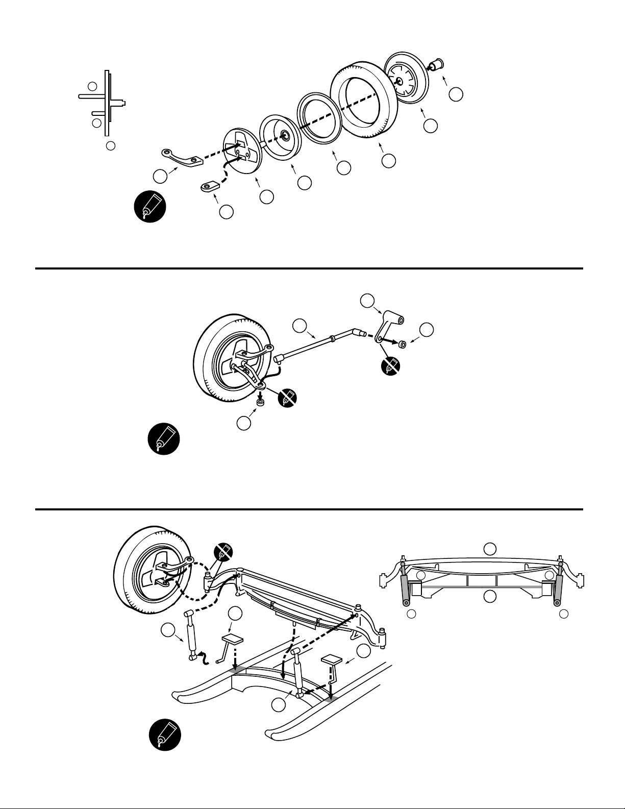
17
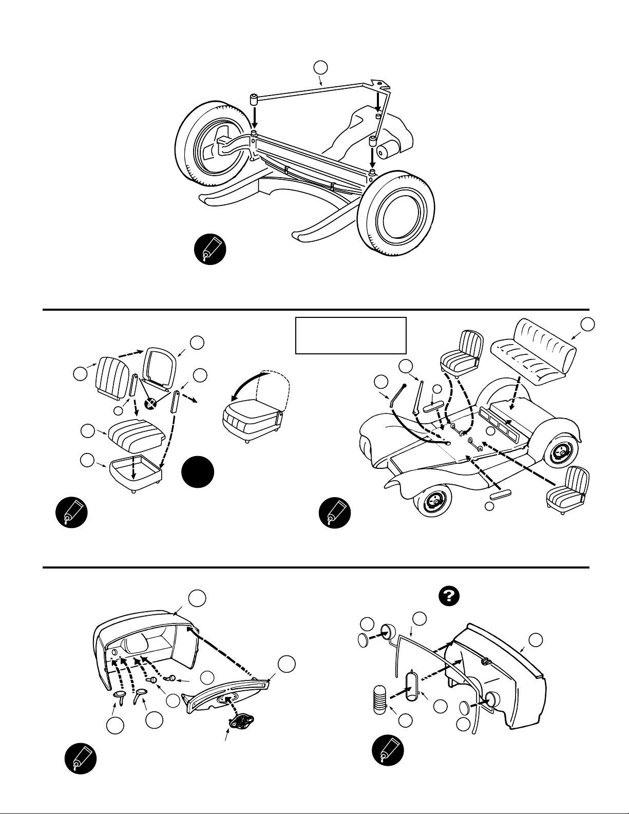
NOTE: All parts shown upside down.
Snap wheel assembly onto stubs.
18
NOTE: All parts shown upside down. Front suspension parts not shown
for clarity. Pass end stubs of tie rod (33) through holes in steering arms
and glue caps (71) on ends.
71
Q
33
Q
71
Q
Be sure to test the fit
of parts Q(33/35) in the
respective holes in mating parts.
Non-glued parts should move
easily for proper movement
of operable features.
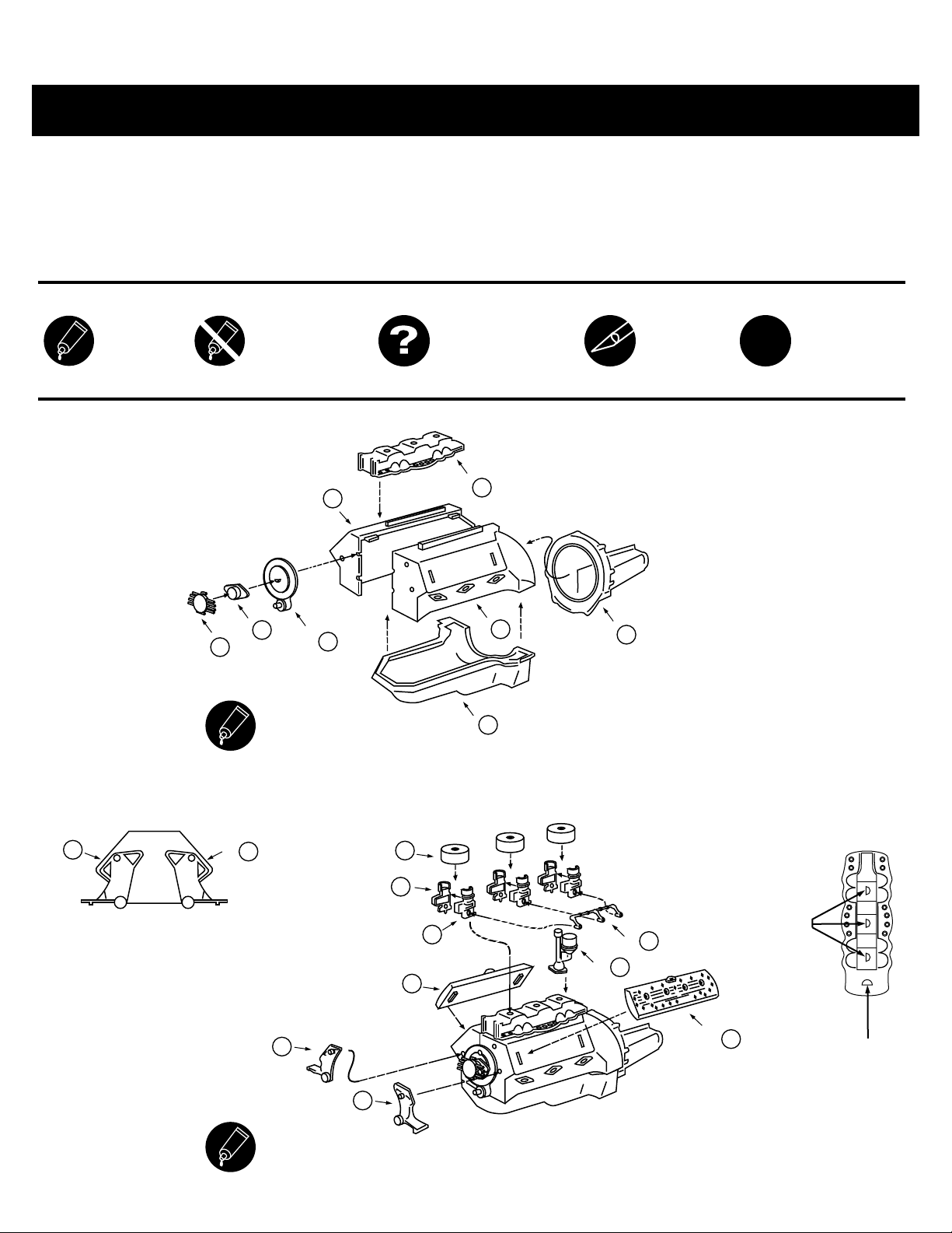
PLEASE NOTE
NOTE
If exhausts are installed in
upper position (exiting sides of engine compartment),
steering shaft must go between second &
third exhaust pipes on left side.
If installed in the downward
position (exiting under engine compartment)
some trimming of exhausts
may be required to clear
steering linkage.
Press fit
20
Turn model over.
Glue together steering box parts (47/48).
Press fit steering box to frame.
Press fit the steering link onto the shaft of part 47.
47
Q
48
Q
19
Cement floorboard D(1) to B (1). Cement fender B(3) in place.
NOTE
Some parts not shown
for clarity.
1
D
2
B
1
B
19
G
18
G
NOTE
Some parts not shown
for clarity.
Parts are shown upside down.
21
Cement battery parts F(22/26) together and glue to frame in position shown.
Cement fenders and floorboard assembly to frame. Cement engine
assembly in position, connecting to driveshaft. Glue exhausts in
your preferred position, then glue steering linkage in place.
26
F
22
F