FG Modellsport Leopard 4 Competition User manual

E.67000_e_011210
Please thoroughly keep this construction manual for spare parts orders!
FG Modellsport GmbH
Spanningerstr. 2
73650 Winterbach-Germany
Phone: +49 7181 9677-0
Fax: +49 7181 9677-20
www.fg-modellsport.de
We congratulate you on buying this FG Competition model. Please check the contents of the construction set,
respectively of the bags. The individual bags have been thoroughly packed by us and their weight and content
has been checked. When purchasing the individual bags, please check their weight and their closure by staples
which must not have been removed or opened and closed several times. It is possible that the weight of an in-
dividual bag deviates by 5 grams. In case of claims due to missing parts, you always need to present the label
indicating the weight at your specialized dealer. By checking the weight of the bag, you may exclude that larger
parts or several parts are missing.
Mounting instruction for 4WD Off-Road Buggy
Leopard 4 Competition, Item N°. 67000
Weight of the individual bags/ boxes:
Item N°. 67000
Bag A = 0,158 kg
Bag B = 1,265 kg
Bag C = 0,791 kg
Bag D = 0,685 kg
Bag E = 0,743 kg
Bag F = 0,887 kg
Bag G = 0,210 kg
Bag H = 0,442 kg
Bag I = 0,388 kg
Bag J = 0,078 kg
Bag K = 0,332 kg
Bag L = 0,362 kg
Bag M = 0,303 kg
Bag N = 0,029 kg
Bag O = 0,390 - 0,400 kg
Bag Q = 0,382 kg
The RCS, accumulators and battery charger are not included in the
delivery volume.

The handling with fuels requires circumspective and ca-
reful handling. Imperatively observe the security advices.
- Refuel only if the engine is switched off!
- Take off the body.
- Thoroughly clean the area around the fuels nipple.
- Remove the fuel filler cap and carefully fill in the fuel mixture.
- Smoking or any kind of open fire is not admitted.
- Fuels might contain solvent-like substances. Avoid contact with skin and
eyes. Wear gloves for refueling. Do not inhale fuel vapors.
- Do not spill any fuel. If you have spilled fuel immediately clean the engi-
ne and the model.
- Make sure that no fuel will get into the soils (environmental protection).
Use an appropriate mat.
- Do not refuel in enclosed rooms. Fuel vapors accumulate at the soil (risk
of explosion).
- Transport and store fuels only in admitted and labeled canisters. Keep
fuel out of the range of children.
- The operator is responsible for any damages caused to third persons in
the operating range of the model, respectively of the engine, if they are
injured or in case of property damage.
- The model must only be passed on to persons who are familiar with this
model and its operation, always provide the operating manual.
- Persons with implanted heart pacemakers must not work on running en-
gines and on live parts of the ignition system when the engine is being
started.
- The engine must neither be started nor operated in enclosed rooms (wi-
thout sufficient ventilation).
- When starting the engine, avoid inhaling the exhausts.
- The model must neither be started nor operated without air filter or wi-
thout exhaust system.
- Before every start perform a functional check of the safety-relevant parts.
- The throttle rods must always return automatically to the idle position.
- Any cleaning, maintenance and repair works must only be performed
with the engine being switched off. The engine and silencers are getting
very hot. In particular do not touch the silencer.
Comments regarding the construction manual:
Before starting the assembly please see through this construction manu-
al. This way you will get an overview of the whole execution.
Please check by means of the parts or bag list if the construction kit is com-
plete and also check the weight of the individual bags for the positions.
Only this way you may be sure that all parts which you need for the as-
sembly are available. If a part is missing, please immediately contact your
specialized dealer.
Table of contents
Position 1-3: Front and rear differential gear
Position 4-8: Belt drive, belt tensioner
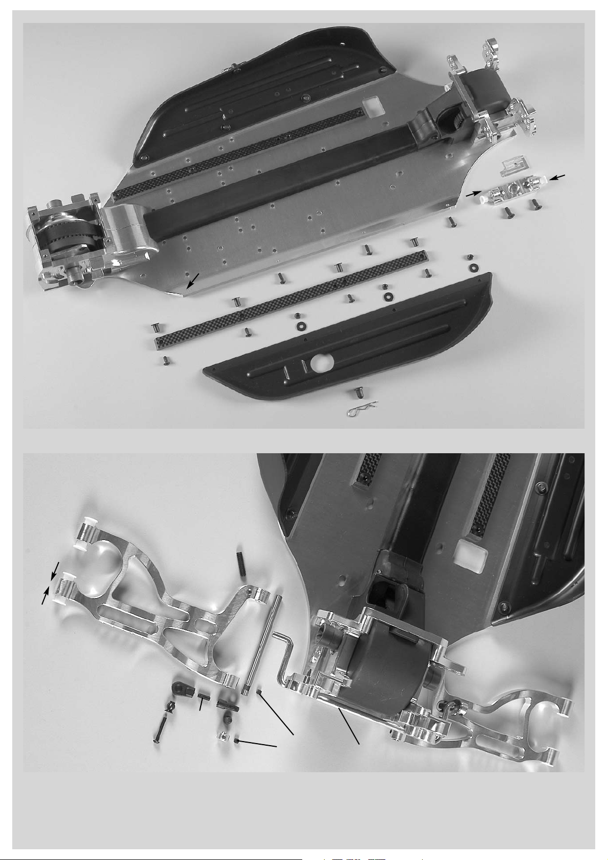
Position 9: CFRP chassis stiffening, ABS splash guards
Position 10-13: Rear axle
Position 14: Shock absorbers
Position 15: Shock mount, spoiler mount, rear damper protection
Position 16-21: Engine, air filter, gear, fuel tank
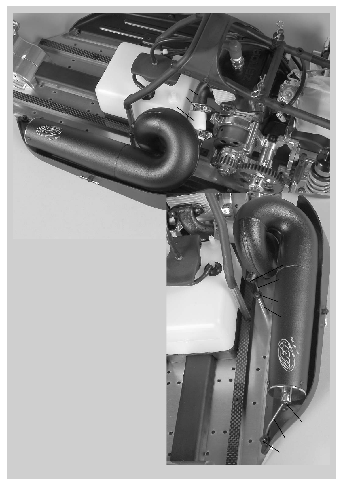
Position 22-25: Starter rope ,roll bar, tuning pipe
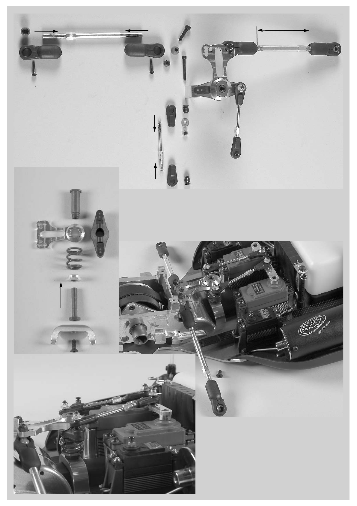
Position 26-32: Servos, receiver box, servo saver
Position 33-35: Wishbones, stabilizer, front uprights
Position 36-37: Front axle plate, front bumper
Position 38-39: Throttle rods
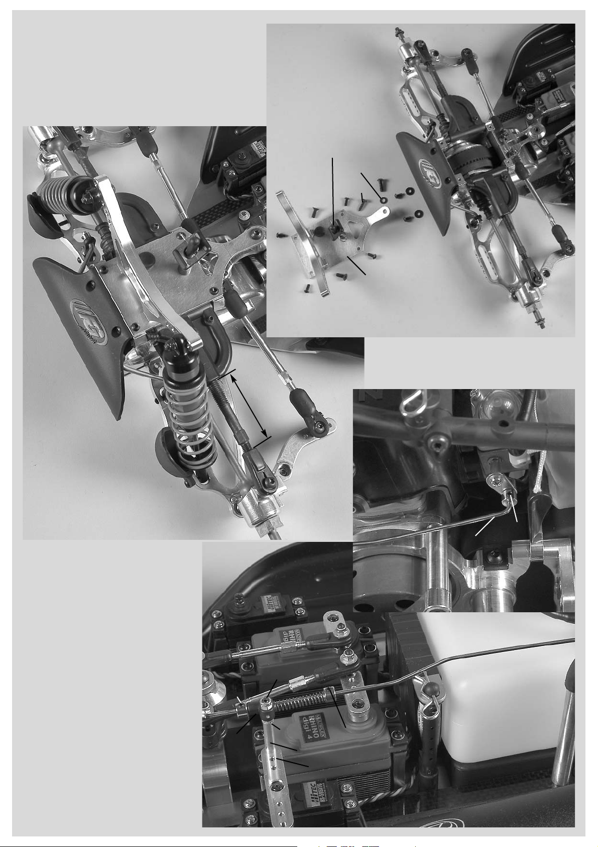
Position 40-45: Hydraulic brake system
Warranty conditions for engines:
FG Modellsport assumes no liability for defects if the engine has been modified by installation of parts of foreign
origin or if engine parts for tuning purposes were worked on or were modified and the damage stands in causal
interrelationship with the modification. Further the liability for defects of power-increased engines is excluded. In
this case also the compensation liability is excluded.

All metric screws need to be secured with thread lock fluid.
Inserting of the diff.
bevel gear wheels or
of the complete pack-
age becomes much
easier if you use the
FG mounting tool Item
N°. 08505.
Alum. differential gear 4-fold self-locking
Diff. bevel
gear B
Axial bearing
5x12x4
Pressure
disk
Diff. bevel gear
self-locking
Friction
disk
Adjusting
screw for self-
locking diff.
Spacer
disk
Buffer
plate
Steel
bush
8x12x5
Needle
bearing
Shim ring
5x17x0,1
Diff. bevel
wheel axle
Position 1
Parts are in
bag C
Position 2
Parts are in
bag C
1. Insert diff. bevel gears B and self-locking bevel gears together with
friction disks and buffer plates in the alum. differential housing as shown
in position 1. Now lubricate both ball diff. driving axles and diff. bevel
wheel axle slightly with some grease and impress them into the alum.
differential housing. The borings of the differential housing must be in
true alignment with the borings of the diff. bevel gears. If you notice a
misalignment of the borings, take the complete package out of the diffe-
rential housing and replace the diff. bevel gears one tooth offset. Then
mount the complete package back into the diff. housing.
2. Press out the diff. bevel wheel axle slightly and push a spacer disk
between diff. bevel gear B and alum. diff. housing. Mount the second
spacer disk in the same way.
3. Press out the diff. bevel wheel axle approx. to the half. Now mount 1x
axial bearing, then both pressure disks with cone against each other to
the centre and finally the second axial bearing. Impress the diff. bevel
wheel axle completely back into the alum. diff. housing. Turn the ball diff.
driving axles and check the differential gear on smooth running. Too
much tooth clearance can be balanced with the enclosed shim rings
5x17x0,1, fix them between alum. diff. housing and spacer disks.
4. Mount the spacer disks to the alum. diff. housing using M4x8 coun-
tersunk screws, use screw retention lacquer.
5. Apply some multi-purpose grease (f.e. Item N°. 06501) on the diffe-
rential bevel gears and insert the o-ring small and large in the provided
groove of the alum. differential housing.
6. Press the front left plastic spacer disk, the front plastic toothed belt
wheel 42 teeth and right alum. spacer disk on the alum. diff. housing as
described in position 1. Fix the complete unit with the M4x40 counter-
sunk screws, use high-strength screw retention lacquer.
7. Screw the adjusting screws for the self-locking differential equally into
the right alum. spacer disk until they touch the pressure disks, use
medium screw retention lacquer.
8. Impress the bearing shafts
6x50mm into the guide pulley
16mm and centric into the too-
thed belt wheel 12 teeth.
Screw
M4x40
Screw
M4x40
Right alum.
spacer disk
Adjusting screw for self-
locking differential
Alum.
differential
housing
Screw buffer plates to
the alum. differential hou-
sing using M4x8 counter-
sunk screws.
Toothed belt
wheel 12 teeth
Bearing
shaft 6x50
Bearing shaft
6x50
Guide pulley
16mm
Front left plastic
spacer disk
Plastic toothed
belt wheel front
42 teeth
Ball diff. dri-
ving axle
Ball diff.
driving axle
Ball bearing
15x28x7
O-ring
small
O-ring
large
Front drive
Hint: The barrier effect of a self-locking differential gear is caused by the torque which is generated when the bevel gears press on the friction
disk respectively the spacer disk and are slowed down by the higher friction. This differential gear can be additionally locked mechanically
through the adjusting screws in the right alum. spacer disk, therefore screw them in in clockwise direction. To lock this differential mechanically,
turn in both adjusting screws symmetrically in clockwise direction. You achieve a lower barrier effect if you unscrew them anticlockwise.

Position 3
Parts are in
bag B
Rear differential
Ball diff.
driving axle
Ball bearing
15x28x7
Screw
M4x40
Needle bea-
ring f. Diff.
Bronze
bush
Alum. differential
housing
Diff. bevel
wheel axle
O-rings
Shim ring
5x17x0,1
Shim rings
8x20x0,1
Diff. bevel gear B
Diff. bevel gear A
Steel gearwheel
48 teeth
Rear plastic tooth
wheel 42 teeth
Right alum.
spacer disk
Rear drive
Slope to the inside
Ball diff. driving
axle
Ball bearing
15x28x7
Screw
M4x40
Alum. differential
housing
Steel gearwheel 48
teeth
Rear plastic tooth
wheel 42 teeth
Right alum.
spacer disk
1. Insert the diff. bevel gears A and B in the alum. diff. housing as des-
cribed in position 3.
2. Lubricate the ball diff. driving axles slightly with some grease and
push it in the diff. housing.
3. Mount the diff. bevel gear axle. If the bevel gear axle respectively the
driving axles can only be pushed in severely or if it cannot be pushed in
at any position, you have to dismantle the bevel gearwheels again. Then
insert them again.
4. If the gearwheels have too much clearance, correct it using the enclo-
sed shim rings. Please make sure that the gearwheel clearance had not
been set too close.
5. Lubricate the diff. bevel gears slightly with multipurpose grease, e.g. Item
N°. 06501.
6. Press the parts on the alum. diff. housing as described in position 3
and in the given sequence: O-ring large, O-ring small, steel gearwheel
48 teeth, rear plastic gear disk 42 teeth, right alum. spacer disk. Fasten
the complete unit using the M4x40 countersunk screws (use the screw
retention high-strength).
Inserting of the diff.
bevel gear wheels or of
the complete package
becomes much easier
if you use the FG
mounting tool Item N°.
08505.
Toothed belt wheel
12 teeth
Left alum.
front axle
housing
Ball bearing
6x16x6
Toothed belt
Guide pulley
16mm
Front differential
mounted
1. Press the front differential gear, 16mm
guide pulley, toothed belt wheel 12 teeth into
the left alum. front axle housing as described
in position 4.
2. Now place the toothed belt as illustrated
on the front differential gear, 16mm guide
pulley, toothed belt wheel 12 teeth as shown
in position 4.
Position 4
Parts are in
bag B+C

Belt pulley
housing right
Plastic bearing seat
1. Press the right alum. front axle
housing on the front differential
gear, guide pulley 16mm, toothed
belt wheel 12 t (as pictured in
position 4).
2. Place the complete alum. front
axle housing on the alum. chassis
and fix it using M4x14 counter-
sunk screws.
Position 5
Parts are in
bag C
Position 6
Parts are in
bag B
Position 7
Parts are in
bag B
Position 8
Parts are in
bag B
All metric screws need to be secured with thread lock fluid.
Alum. front
axle hou-
sing left
Alum. front
axle hou-
sing right
Toothed belt
Alum. chassis
Front
differential
gear
Screw
M4x14
Toothed belt
Alum. chassis
Rear
differential
gear
Alum. rear axle
mount left
Alum. rear
axle mount
right
Top part
belt channel
Bottom part
belt channel
Screw
M5x14
Screw
4,2x16
Screw
4,2x16
1. Place the toothed belt on the rear differential gear as
pictured in position 6.
2. Press the left and right alum. rear axle mounts on
the ball bearing of the rear differential gear as shown in
position 6.
3. Place the left and right alum. rear axle mounts on
the alum. chassis and fix them using M5x14 counter-
sunk screws.
4. Lay the bottom part of the belt channel on the bot-
tom part of the toothed belt as described in position 6.
Now press the top part into the bottom part of the belt
channel. Push the complete belt channel into the ope-
ning of the alum. front axle housing. Make sure the
toothed belt is running smoothly.
5. Fix the belt channel from
underneath to the alum. chassis
using the 4,2x16 countersunk
screws.
Mount the closed side of the lower belt chan-
nel facing upwards. The teeth of the toothed
belt are not allowed to touch each other.
Screw
M4x14
Disk Ø4,3
Belt pulley
housing left
Mounting position
for toothed belt
wheel 42 teeth
Mounting posi-
tion toothed belt
wheel 40 teeth
Collar
Ball bearing
10x19x7
Bearing shaft
for belt pulley
housing
1. Impress the plastic bearing
seat with inbound collar (pay
attention to fitting position) in
the left and right belt pulley
housing as described in posi-
tion 7.
2. Push the bearing shaft for the belt pulley hou-
sing centrically in the 3 ball bearings 10x19x7.
3. Impress the bearing shaft which is equipped with
ball bearings in the bearing seat of the left and
right belt pulley housing and fix it with M4x14
pan-head screws and Ø4,3 disks.
Hint: The position of the front bearing seat is made for
the front plastic toothed belt wheel with 42 teeth. The
position of the rear bearing seat is made for the front
plastic toothed belt wheel with 40 teeth.
1. Place the mounted belt pulley housing on toothed
belt and belt channel as described in position 8 and fix
it on the alum. chassis using the 4,2x16 countersunk
screws. For this purpose, slightly move the belt.
2. When the assembly is performed, turn the belt in run-
ning direction. Make sure the belt is easily rotatable.
Rear axle cover
3. Press the rear axle cover
between the alum. rear axle
mounts and fix it with alum.
connecting brace, M4x20 pan-
head screw and Ø4,3 disk.
Screw
M4x20
Disk Ø4,3
Alum.
connection
brace
Alum. rear
axle mount
right
Alum. rear
axle mount
left
Alum. chassis
Position 9
Parts are in
bag A+B
Position 10
Parts are in
bag B+D
Alum. rear
axle mount
right
Alum. rear
axle mount
left
Alum. chassis
Screw
M5x14
Alum. adju-
sting key 2°
Alum. wish-
bone fixing
2°, left
Guide bush
with collar
Impress
guide bushes
Screw
M4x10
Screw
M4x10
Body clip
Body bolt
Screw
M4x12
Screw
M4x12
ABS splash guard
CFRP chas-
sis stiffening
Insert bush for
chassis stiffening
Disk Ø4,3
Stop
nut M4
1. Press the M4x12 pan head screws from underneath into the
alum. chassis and fix the le/ri ABS splash guard using Ø4,3 disks
and stop nuts M4. Do not fasten the front left ABS splash guard.
2. Press the body bolts from the inside into the ABS
splash guard and fix with some superglue, then
clip on the body clip.
Do not fasten the front
left ABS splash guard.
3. Press the insert bushes for the chassis stiffening
from the top into the CFRP chassis stiffenings, then
mount them from below to the alum. chassis using M4x10
countersunk screws. Left and right CFRP chassis stiffenings are dif-
ferent, pay attention to the borings.
4. Impress the guide bushes with col-
lar into the le/ri alum. wishbone
fixings 2° and mount them together
with alum. adjusting key 2° and
M5x14 countersunk screws to the left
and right rear axle mounts.
Screw
M3x20
Guide bush
with collar
Rear lower
alum. wish-
bone
Headless
pin M5x20
Headless
pin M4x4
Headless
pin M4x14
Impress
guide bushes
Stabilizer
5mm
Steel ball
7mm
Ball
joint
7mm
Steel ball
Ø7 x 5mm
Alum.
collet
5mm
1. Press the guide bushes
with collar from the inside
and outside into the rear
lower alum. wishbones.
All metric screws need to be secured with thread lock fluid.
4. Screw the 7mm ball joints on the M4x14 headless pins until they are in contact and until they are 90° twisted. Impress a steel ball 7mm and
steel ball Ø7x5mm each one side of the ball joints 7mm.
5. Press the ball joints 7mm with the side of the steel ball Ø7x5mm on each side of the 5mm stabilizer and fix them using the 5mm alum. retai-
ning collar (collar facing the ball joint) and the headless pin M4x4.
6. Mount the ball joints 7mm with the side of the steel ball 7mm to the rear lower alum. wishbones (with the collar of the steel ball facing bak-
kwards) using M3x20 pan head screws. Impress the 5mm stabilizer into the alum. rear axle mounts.
2. Screw the headless pin
M5x20 centrically using screw
retention from the top into the
rear lower alum. wishbones.
3. Fix the rear lower alum. wishbones with wishbone pins
6x85mm to the alum. wishbone fixings 2° left/right, groove
and thread must face backwards. Make sure the mounted
wishbones can be moved easily up and down.
Hint: To withdraw the rear
lower wishbone pins
6x85mm screw an M4
screw into the tap hole
of the wishbone pins
6x85mm and pull them out.
Wishbone pin 6x85

Apply lubri-
cating grease
Slightly lubricate the
ball driving shaft
Protection bellow
Protection bellow
Ball diff. axle
Ball driving
axle
Distance
disks
Balls for
driving shaft
Position 11
Parts are in
bag D
Position 12
Parts are in
bag D
Position 13
Parts are in
bag D
All metric screws need to be secured with thread lock fluid.
Mounting of the ball driving shafts
Stick the distance disks into the round recess of the ball
driving axles as well as in the ball diff. axle using some
multipurpose grease. Mount the protection bellows to the
ball driving shafts according to the illustration. Slightly gre-
ase the ball area when mounting the protection bellow.
Apply some lubricating grease on the ball holes of the dri-
ving shafts and impress the balls. The balls will be held by
the lubricating grease and this way the driving shaft can be
mounted more easily. Now push the complete ball driving
shaft into the differential axle and driving axle. Push the
protection bellows over the ball diff. axles and driving
axles.
Adjusting clips
Use high-strength
screw retention
Adjust rear upper wishbo-
nes to approx. 72 mm
Rear lower
alum. wish-
bone
Headless
pin M4x4
Alum. square
wheel driver
9,5mm/M6
Balls
for
driving
shaft
Adjusting clips
Securing
disk Ø5
Securing
disk Ø5
Wishbone
pin 6x65
Wishbone
pin 6x63
Ball driving
axle
Ball driving
shaft
Distance
disk
Wheel nut
Headless
pin M6x6
Headless
pin M3x3
Alum.
upright
left
Screw
M5x25 Screw
2,9x13
Screw
2,9x13
Adjusting screw
ri./le. M7x110
Ball joint
10mm M7
Alum. ball
retaining
collar
Ø10x15
Alum. joint
ball Ø10x13
Ball diff.
driving axle
1. Press the ball driving axles of the premounted ball driving set
(position 11) into the alum. uprights equipped with ball bearings and
fix the alum. square wheel driver 9,5mm/M6 (shoulder facing the ball
bearing) on the areas of the ball driving axles (use high-strength
screw retention).
2. Push the alum. uprights and wishbone pins 6x65mm into the rear
lower alum. wishbones as shown in position 12. Secure the wishbo-
ne pins with Ø5 securing disks.
3. Press each one adjusting clip front and rear between the alum.
uprights and rear lower alum. wishbones on the wishbone pins,
secure the alum. uprights with M3x3 headless pins. Check the alum.
uprights on free movement.
4. Screw the ball joints 10mm M7 on the adjusting screws ri/le M7x110mm, impress alum. joint ball Ø10x13 and alum. ball retaining collar
Ø10x15 each one side of the ball joint 10mm M7, then screw the 2,9x13 pan head screws into the ball joints 10mm M7 and adjust the ball clea-
rance (position 12).
5. Mount the wishbone pins 6x63mm (with the side of the alum. ball retaining collar Ø10x15, collar in driving direction) through the premounted
upper wishbones, now mount the alum. rear axle mounts ri/le into the lower inside boring and secure them using Ø5 securing disks and M4x4
headless pin.
6. Fix the premounted upper wishbones through the alum. joint ball Ø10x13 (collar facing the alum. upright) using M5x25 pan head screws to the
alum. uprights le/ri.

Position 14
Parts are
in bag E
Position 14a
Parts are in
bag E
O-ring
Ø22x1,5
Plastic bush
Ø5/Ø7x6,5
Plastic
bush
Ø4,5/Ø7x4
Plastic guiding
disk
Volume
control
Ø20 Plastic damper
piston
Upper alum.
shock absor-
ber seal
Plastic
adjusting
ring
Lower alum.
shock absor-
ber seal
Lower alum.
shock absor-
ber seal
Lower alum.
shock absor-
ber seal, pre-
mounted
Gasket Ø4,5
Lower shock
fastening,
reinforced
Threaded
piston rod,
short + long Threaded
piston rod,
short + long
Pliers Item N°.
06854
O-ring
Ø24x1,5
O-ring
Ø20x1,5
Position 14d
Parts are in
bag E
Position 14c
Parts are in
bag E
Position 14b
Parts are in
bag E
Upper alum.
shock absor-
ber seal
Disk
Ø3,2
Stop nut
M3
Lower alum.
shock absor-
ber seal, pre-
mounted,
short + long
Alum. shock
absorber
housing
short + long
Shock absor-
ber oil 1000
Shock absorber
long, mounted
Shock absorber
short, mounted
Plastic adju-
sting ring
Plastic
adjusting
ring
Plastic spring
guide
Damper
pressure
spring
orange
2,4x40
Damper
pressure
spring
orange
2,4x10⁵
Damper
pressure
spring red
2,4x10⁵
Alum. spring
plate
1. Press plastic bush Ø5/Ø7x6,5 into the upper alum. shock absorber seals as shown in position 14 and insert the o-ring Ø22x1,5 in the groove.
2. Insert o-ring Ø24x1,5 in the groove of the plastic adjusting rings.
3. Mount the o-ring Ø20x1,5 into the groove of the lower alum. shock absorber seals.
4. Screw the lower reinforced shock fastenings on the thread of the threaded piston rods short and long until the thread can not be seen anymo-
re. Make sure you do not damage the piston rod. Therefore we recommend to use the pliers Item N°. 06854.
5. Impress the plastic bushes Ø4,5/Ø7x4 and gaskets Ø4,5 into the lower alum. shock absorber seals, then press the volume control Ø20 on the
plastic guiding disks and impress into the lower alum. shock absorber seals (see position 14a).
6. Push the threaded piston rods short and long carefully and with some shock absorber oil through the premounted alum. shock absorber seals
as shown in position 14b, then mount the plastic damper piston with disk Ø3,2 and stop nut M3. Do not tighten the stop nuts M3 too firm, make
sure the plastic damper pistons can still be moved.
7. Screw the plastic adjusting
rings with some oil on the alum.
shock absorber housing short and
long as shown in position 14c.
8. Fix the assembled alum. shock
absorber seals with short piston
rod into the short shock absorber
housing.
Fix the assembled alum. shock
absorber seals with long piston
rod into the long shock absorber
housing.
9. Fill the shock absorbers with
shock absorber oil up to the top
and move the piston rod carefully
several times in and out so that
the air bubbles in the oil come
upwards. As soon as no air bub-
bles appear anymore, pull the
piston rod completely out and lock
the shock absorbers with the
upper alum. shock absorber seals.
10. Mount the orange damper
pressure spring 2,4x40, the plastic
spring guide and red damper pres-
sure spring 2,4x10⁵ on the long
rear shock absorbers and secure
them with the alum. spring plates
as shown in position 14d. Fix the
orange damper pressure spring
2,4x10⁵ on the short front shock
absorbers and secure it using the
alum. spring plates.

Screw
M5x40
Engine
Alum. engine
mount small
Stop
nut M5
Stop
nut M5
Headless
pin M5x20
Screw for carrier
M6x14 with disk
Carrier for
clutch shoes
Engine flan-
ge for engine
quick
fastening
1. Mount the small alum. engine mount to the engine using
M5x40 pan head screws and counter with M5 stop nuts.
For this purpose the original screws of the engine have to
be removed.
2. Apply screw retention lacquer on the four headless pins
M5x20 and screw them into the engine housing until they
poke out of the housing approx. 9mm.
3. Press the engine flange for the engine quick fastening
(with the cutout facing the cylinder) on the housing or
respectively the headless pins and fix it using M5 stop
nuts.
4. Fix the carrier for the clutch shoes to the engine using
an M6x14 hexagon screw with pressed on disk.
Hint: If the FG piston stop pin Item N°. 08542 is used, the
assembling of the clutch shoe carrier will be considerably
simplified.
Position 15
Parts are in
bag B,E+M
Position 16
Parts are in
bag H
All metric screws need to be secured with thread lock fluid.
Screw
M4x20
Screw
M5x25
Screw
M4x14
Screw
M5x10
Screw
4,2x32
Mount for
pull start
Rear shock
absorber
mounted
Rear CFRP
damper pro-
tection
Screw
M4x18
Disk Ø4,3
Disk Ø5,3
Stop nut
M5
Body clip
Plastic brace
Ø10x80
Adjusting part
spoiler mount
Spoiler
mount
1. Fix the rear alum. damper plate
to the le/ri alum. rear axle mounts
using M4x18 pan head screws
and disks Ø4,3 ( Mount the cut-
out of the alum. shock mount in
driving direction).
2. Mount the rear assembled lower
shock absorbers to the rear lower
alum. wishbones (medium threa-
ded hole) using M4x20 pan head
screws. Screw M5x25 pan head
screws in the outer threaded holes
of the alum. damper plate rear,
then fix the shock absorbers at the
top using disks Ø5,3 and stop
nuts M5.
3. Mount the rear CFRP damper
protection to the le/ri alum. rear
axle mount using M4x18 pan head
screws and disks Ø4,3 on both
sides of the rear CFRP damper
protection.
4. Fix the spoiler mount at the rear
alum. damper plate using M4x14
cylinder head screws, mount the
plastic brace Ø10x80mm and the
adjusting parts spoiler mount in
between using 4,2x32 pan head
screws as shown in position 15.
Clip the body clips on the adju-
sting parts spoiler mount.
5. Assemble the mount for the pull
start to the rear alum. damper
plate using M5x10 pan head
screws as shown in position 15.
Rear alum.
damper
plate

Position 17
Parts are in
bag H+J
Position 18
Parts are in
bag I
Screw
M5x16
Screw
4,2x13
Screw
4,2x13
Screw
4,2x16
Engine
Manifold
Silencer gasket
O-ring for
air filter
adapter
Air filter
adapter
Filter cover
Foam filter
Basic
body
Clutch
shoes
Clutch spring
Set screw for clutch shoes
Shaft washer
Driving direction
Disk
6x15x1
Screw
M6x10
Screw
M5x14
Screw
M4x14
Screw
M4x14
Screw
M6x10
Screw
M6x16
Screw
M4x10
Screw
M5x10
Steel gearwheel
14 teeth
Headless
pin M5x5
Headless
pin M5x5
Headless pin
M6x6
Tuning gear
shaft
Pre-filter
for intake
air filter
longer
shaft flats
Steel
gearwheel
46 teeth
Set screw
10x16x1
Alum.
gear
plate
Alum.
gear flange
engine mount
Set screw
10x16x1
Steel
gearwheel
18 teeth
Alum.
gearwheel
adapter
Tuning
clutch bell
Engine flange
for engine
quick
fastening
2. Press the oiled foam filter on the basic body and fix it with the filter
cover and a 4,2x16 countersunk screw.
3. Mount the manifold to the engine using M5x16 pan head screws and
silencer gasket.
Hint: The enclosed foam filter is ready-to-use and oiled. If at a later point
of time a filter is required which is ready-to-use, please proceed as fol-
lows: in order to oil the foam filter place the filter together with some FG
filter oil for foam filter Item N°. 06441 in a plastic bag and press together
to rub it in.
2. Impress the tuning clutch bell with
two set screws 10x16x1 in the alum.
gear plate as shown in position 18,
now mount set screw 10x16x1 and
steel gearwheel 18 teeth on the flats
of the tuning clutch bell using M5x5
headless pins, secure with M6x10
pan head screw.
3. Assemble the alum. gear plate at
the alum. gear flange-engine mount
using M4x14 cylinder head screws.
Screw M5x14 pan head screw into
the alum. gear flange-engine mount,
but do not tighten yet.
4. Press the tuning gear shaft at the
side with the longer shaft flats flush
into the alum. gearwheel adapter and
secure with M6x6 headless pins and
M6x10 pan head screws.
5. Mount steel gearwheel 46 teeth to
the alum. gearwheel adapter using
M5x10 pan head screws.
6. Press the tuning gear shaft through
the ball bearings of the alum. gear
plate and alum. gear flange-engine
mount.
7. Press the steel gearwheel 14 teeth
on the tuning gear shaft as shown in
position 18 and fix it using M5x5
headless pins on the flats of the
tuning gear shaft, secure with M6x16
countersunk screw. Use high-strength
screw retention.
8. Plug the complete gear unit on the
engine flange for engine quick faste-
ning.
Disk Ø4,3
Gearwheel
cover
Optional accessory
1. Pull the pre-filter for
the intake air filter over
the completely moun-
ted air filter, pull it
together with the lace
and fix it with a tie.
9. Fix the gearwheel
cover to the alum.
gearflange-engine
mount using an
M4x10 pan head
screw and Ø4,3 disk.
4. Kupplungsfeder in die Kupplungsbacken einhängen und Kupplungsbacken nach Abbildung aufeinander schieben (werksseitig vormontiert).
5. Place the shaft washers on the set screws for the clutch shoes and push them from the side with the arrows (running direction of the engine)
into the clutch shoes, then fix it on the clutch shoe carrier using 6x15x1 disks.
Hint: If the FG piston stop pin Item N°. 08542 is used, the assembling of the clutch will be considerably simplified.
1. Insert the o-ring
for the air filter adap-
ter in the basic body
and fix it to the air fil-
ter adapter using
4,2x13 countersunk
screws.

Position 19
Parts are in
bag H+K
Position 20
Parts are in
bag I
All metric screws need to be secured with thread lock fluid.
Screw
M4x14
Screw
4,2x16
Screw
4,2x16
Lower tank mount
Engine
fixing disk
Screw
M4x25
Disk
Ø4,3
Screw
M4x6
1. Insert the premounted engine in the alum. chassis as illustrated in position 13 and fix it
using an M4x25 pan head screw and disk Ø4,3 through the left alum. rear axle mount, also
fix it with the alum. connecting brace at the alum. gear flange-engine mount. Just apply the
M4x25 pan head screw, do not tighten yet (see also position 20).
2. Mount the pre-assembled engine in the alum. chassis using M4x14 countersunk screws
and engine fixing disks.
3. Fix the tank on the lower tank mount using M4x6 countersunk screws as shwon in posi-
tion 19, use medium screw retention.
4. Mount the pre-assembled tank with lower tank mount
on the alum. chassis using 4,2x16 countersunk screws.
Tank complete
Screw
M5x14
Alum. gear flan-
ge-engine mount
2. Tighten the M5x14 pan
head screw at the alum.
gear flange-engine mount.
Screw
M4x25
Disk
Ø4,3
Alum. rear
axle mount
left
Alum. con-
nencting
brace
1. Tighten the M4x25 pan
head screw after tightening
the engine fixing screws.

Position 21
Parts are in
bag K
Position 22
Parts are in
bag B
Position 23
Parts are in
bag M
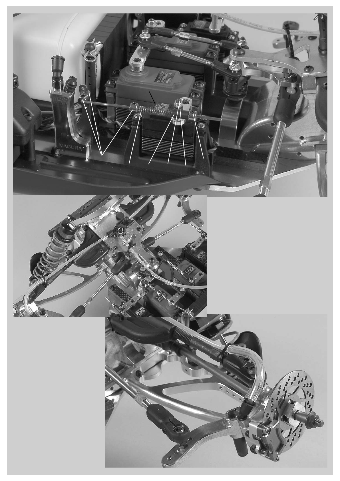
Install fuel hoses as illustrated and
shorten if necessary.
Return
hose
Intake hose
Venting hose
Screw
4,2x22
Screw
4,2x22
Screw
4,2x22
Screw
M4x25
Screw
4,2x13
Screw
4,2x32
Plug pro-
tection
Plastic
brace long
Plastic
brace short
Alum.
distance
Ø10x70
Plastic brace
Ø10x60
Body
mount
Roll bar
short
Headless pin
M5x30
Headless pin
M4x20
Alum.
damper
plate rear
Body clip
Alum. chassis
1. Screw M4x20 headless pins centric into
the short roll bar and screw the alum.
distances Ø10x70mm on top, then mount
the complete roll bar through the CFRP
chassis stiffening to the alum. chassis
using M4x25 countersunk screws.
2. Screw M5x30 headless pins centric into
the plastic braces Ø10x60 as shown in
position 23, then screw on the long plastic
braces.
3. Fix the body mounts from the bottom at
the long plastic braces into the front boring
using 4,2x22 countersunk screws and
press the body clips on. Mount the long
pre-assembled plastic braces to the rear
alum. damper plate and to the short front
roll bar using 4,2x22 and 4,2x32 pan head
screws as shown in position 23.
4. Fix the short plastic brace to the long
plastic brace using 4,2x22 pan head
screws as illustrated in position 23.
5. Assemble the plug protection at the long
plastic braces using 4,2x13 countersunk
screws.
Clip the rope star-
ter in the holder
Position 24
Parts are in
bag O
Position 25
Parts are in
bag O
All metric screws need to be secured with thread lock fluid.
Alum. chassis
Fixing wire
for silencer
Fixing wire
for silencer
Manifold
Exhaust hose
Hose clamp
FG Steel-Power
Tuning pipe
FG Steel-Power
Tuning pipe
Screw M4x14
Disk Ø4,3
Stop nut M4
Screw M4x10
Disk Ø4,3
Alum.
distance
Ø8x37,5
Headless
pin M5x5
Headless
pin M5x5
Heat one end of the exhaust hose slightly
with a lighter and press it on the FG Steel-
Power Tuning pipe as shown in position 24,
then fix it using a hose clamp.
Heat up the exhaust hose once again and
press it with the second hose clamp on the
manifold, then fasten it.
1. Fix the alum. distance Ø8x37,5 to the alum. chassis using M4x14
countersunk screw. Bend the fixing wire for the FG Steel-Power
Tuning pipe as illustrated in position 25 and fasten it at the alum.
distance Ø8x37,5 using M4x10 pan head screw and disk Ø4,3.
2. Bend the second fixing wire for the FG Steel-Power Tuning pipe as
illustrated in position 25 and fix it at the alum. chassis in the front left
side by using M4x14 pan head screw, disk Ø4,3 and stop nut M4.
Clamp the fixing wire using an M5x5 headless pin. Adjust and fix the
Tuning pipe with both fixing wires in a way that the pipe does not
touch other parts.

1. Mount the adjustable body mounts on the alum. chassis
using 4,2x16 countersunk screws. Mount 2,9x9,5 pan head
screws in the second boring from the top of the adjustable
body mounts, press the o-rings Ø6x3 on and secure the
alum. battery holding brace with body clips.
Position 26
Parts are in
bag L
Position 27
Parts are in
bag L
Position 28
Parts are in
bag L
All metric screws need to be secured with thread lock fluid.
Screw
M3x16
Disk Ø3,2
Distanzbolzen
Ø8x28
Before you start mounting the remote control components, please
also thoroughly read the enclosed RC manual and deal with trans-
mitter, receiver and servos. Charge the receiver and transmitter bat-
teries and check the parts on their function.
Alum. servo
mount
Screw
4,2x13 Screw
4,2x13
Screw
4,2x16 Screw
4,2x16
Screw
4,2x16
Screw
M4x10
Screw
M4x10
Disk
Ø4,3
Plastic servo
mount small
Brake
servo
Steering servo
Steering servo
Throttle/brake
servo
Screw
2,9x9,5
Screw
2,9x19
Aerial tubing
Aerial mount
Receiver box
Alum. chassis
2. Mount distance bolts Ø8x28mm to the right ABS
splash guard using 4,2x13 pan head screws and
disks Ø4,3 as shown in position 26.
3. Fix the small plastic servo mount to the alum.
chassis using 4,2x16 countersunk screws. Mount
the throttle/brake servo and brake servo into the
small plastic servo mounts using the enclosed
fixing rubber bushings and screws as shown in
position 26.
4. Fix the alum. servo mount to the alum. chassis
using M4x10 countersunk screws. Mount the stee-
ring servos into the alum. servo mounts using the
enclosed fixing rubber bushings, M3x16 pan head
screws and disks Ø3,2 as shown in position 26.
5. Assemble the receiver battery to the alum. bat-
tery brace using insulating tape as illustrated in
position 27.
6. Fix the aerial mount at the top part of the recei-
ver box using a 2,9x19 pan head screw as shown
in position 28. Press the aerial tubing into the aerial
mount and clamp it using a 2,9x9,5 pan head
screw.
7. Press the bottom part of the receiver box on the
distance bolts Ø8x28mm. Connect the servo cable,
battery cable a.s.o. to the receiver and check on
function.
8. To lead the cables through you have to drill a
hole of approx. Ø8mm at a suitable place of the
receiver box top.
9. Store receiver and the rest of the cables in the
receiver box, push thew aerial cable of the receiver
into the aerial tubing.
10. Place an o-ring between the receiver box bot-
tom and receiver box top for sealing.
11. Screw the receiver box on the distance bolts
Ø8x28mm using 4,2x16 pan head screws.
ABS splash
guard
Alum. bat-
tery holding
brace
Receiver battery
Due to the constricted space
conditions we recommend to
use the FG Mini Racing pack
06543/01 for the receiver/
servo power supply. Additio-
nally the FG receiver cable
Item N°. 06547/02 or FG recei-
ver cable with switch FG/JR
Item N°. 06551 is required.
Hint: Cover the bottom part of the receiver box with some foam in order to protect the
receiver against vibrations.
Screw
4,2x16
Adjustable body
mount
Screw
2,9x9,5
O-ring
Ø6x3
Body clip
Position 29
Parts are in
bag L
Position 30
Parts are in
bag L
Position 31
Parts are in
bag L
Position 32
Parts are in
bag L
Disk Ø3,2
1. Screw the ball joints 10mm M7 on the adjusting screws
ri/le M7x110mm as shown in position 30 and impress the
alum. joint balls in the ball joints 10mm M7, screw 2,9x13
pan head screws into the ball joints 10mm M7 and adjust
the ball clearance. Fix the mounted track rods to the pre-
assembled servo saver (collar of the alum. joint ball must
face the mounted servo saver, see illustration) using M4x16
cylinder head screws and stop nuts M4.
Servo saver
axle
Tension sleeve
for servo saver
Alum. servo
saver strap Alum. servo
saver strap
Alum. servo
saver, Part B
Servo
saver
Part A
Servo
saver
spring
Nut M10 for
servo saver
Screw
M5x16
Alum. joint ball
Alum.
joint
ball
Ball joint
7mm
Ball joint
7mm
Steering rods
ri./le., M4x56
Adjusting screw
ri./le. M7x110
Steel ball
7mm
Steel ball
7mm
Steering rods
mounted
Track rod
mounted
Servo saver
mounted
Screw
M4x16
Screw
M3x25
Screw
2,9x13
Screw
2,9x13 Stop
nut M4
Stop
nut M3
Ball joint
10mm M7
Ball joint
10mm M7
1. Impress the tension sleeve for servo saver from the top through alum. servo saver part B and servo
saver part A as shown in position 29.
2. Mount the servo saver spring with nut M10 for servo saver on the thread of the tension sleeve
for servo saver as shown in position 29 and check servo saver on smooth running.
3. Lubricate the servo saver axle slightly and press it from the bottom into the tension sleeve as
shown in position 29.
4. Fix the alum. servo saver strap at the servo saver axle using an M5x16 countersunk screw.
Adjust track rod to
approx. 71 mm
2. Screw ball joints 7mm on the track
rods ri/le M4x56mm and impress
steel balls 7mm into the ball joints.
3. Screw M3x25 pan head screws
from the bottom into the inner
borings of the mounted servo saver
as shown in position 30. Fix the stee-
ring rods to the mounted servo saver
(the collar of the steel ball 7mm must
face the servo saver) using disks
Ø3,2 and stop nuts M3 on the M3x25
pan head screws
2. First mount an assembled steering rod (collar of the ball
must face towards the servo arm) to the servo arm using
M3x18 pan head screw, disk Ø3,2 and stop nut M3 as shown
in position 32. Press the servo arm on the toothing of the stee-
ring servo as illustrated in position 32 and fix it with enclosed
screw. The servo arm should be mounted in 90° position to the
steering servo, it may be necessary to shorten it depending on
the version. Now fix the second assembled steering rod to the
second servo arm in the same way, both steering rods must
have the identical length, make sure you are able to press the
servo arm easily and without any resistance on the toothing of
the steering servo.
Screw
M4x10
Alum. chassis
Servo arm
Screw M3x18
Disk Ø3,2
Stop nut M3
Steering rods
mounted
Servo saver
mounted
Mount the pre-assembled servo saver
with alum. servo saver strap on the alum.
chassis as illustrated in position 31 using
M4x10 countersunk screws.
1. Switch the remote control
on and set the trimming of the
steering to mid-position.

Screw M4x12
Screw
4,2x22
Alum. stee-
ring lever
Plastic stee-
ring stop
shortened
Alu-Achsschenkel
vorne links
Front right
alum. uprights
Ball bearing
15x28x7
Ball bearing
17x26x7
Mount the alum. steering lever to the front alum.
uprights right/left using M4x12 cylinder head screws as
shown in position 34. Fix the plastic steering stop shor-
tened to the alum. steering levers using 4,2x22 pan
head screws.
Position 33
Parts are in
bag F
Position 34
Parts are in
bag F
Position 35
Parts are in
bag F
All metric screws need to be secured with thread lock fluid.
Screw
M4x16
Screw M3x18
Headless pin
M3x3
Stabilizer
mount front
Collet 4mm
Steel ball Ø7 x5mm, Ø4
Stabilizer
4mm front
Headless pin M4x14
Steel ball 7mm
Ball joint 7mm
Screw
M3x6
Headless
pin M5x16
Wishbone pin 6x10⁶
Ball bush
Front lower
alum.
wishbone
Alum. front
axle housing
Alum. front
axle housing
Guide bush
with collar
1. Secure the impressed ball
bushes in the front lower alum.
wishbones with M3x6 pan head
screws.
2. Press the guide bushes with
collar into the front lower alum.
wishbones.
3. Screw the M5x16 headless
pins centric from below into the
front lower alum. wishbones as
shown in position 33 (use screw
retention).
4. Screw ball joints 7mm on the M4x14 headless pins until they are in contact and 90°
distorted. Impress each one steel ball 7mm and steel ball Ø7x5mm, Ø4 in one side of
the ball joints 7mm.
5. Press the ball joint 7mm (steel ball side Ø7x5mm, Ø4) on each one end of the front
stabilizer 4mm and fasten with collet 4mm and headless pin M3x3.
6. Mount the ball joint 7mm (steel ball side 7mm) to the front lower alum. wishbones
(collar of the steel ball must face forwards) using M3x18 pan head screws.
7. Impress the front stabilizer mount with front stabilizer 4mm into the alum. front axle
carrier as shown in position 33 and fix with M4x16 pan head screws.
Hint: To remove the front lower wishbone pins 6x106mm screw an M4 screw into the
threaded hole of the wishbone pin 6x106mm and pull it out.
Screw
M4x12
Screw
M4x20
Screw
4,2x22
Alum.
steering
lever
Nut M4
Plastic
steering
stop
shortened
Front alum.
upright
Front lower
alum. wishbone
Securing
disk Ø5
Adjusting
clips
Headless
pin M6x6
Headless
pin M5x20
Front upper
plastic
wishbone
Wishbone
thread rod
M10/M8x108
Wishbone pin 6x87
Screw
Ø5,3
Disk
Ø5,3
Screw
M5x25
Screw
M5x25
Wheel nut
Ball
joint
for M8
Cardan
joint for
front axle
Alum.
joint ball
Ø5/10x15mm
Taper
disk
Alum.
square
wheel driver
9,5mm/M6
Hint: Always mount the
taper disks with the thinner
side facing the ball
bush.
Track rod
Place the front lower alum. wishbones in the alum.
front axle housing as shown in position 33 and impress
the wishbone pins 6x106mm (threaded hole must face for-
wards) into the alum. front axle housing and front lower alum. wishbones. Make
sure the wishbones can be moved easily up and down.
Tipp: The front alum. uprights on the right and left
side are the same, according to the position of alum.
steering lever and plastic steering stops they have to
be built differently.
Protection
bellow
Balls for
driving
shaft
Distance
disk
Ball
diff.
driving
axle 6. Impress the cardan joint driving shafts in the pre-
assembled alum. uprights left and right and mount alum.
square wheel driver 9,5mm/M6 (offset facing the bearing)
with M6x6 headless pins on the flats of the cardan joints
for front axle. Use high-strength screw retention.
7. Fix the le/ri alum. uprights to the lower alum. wishbones
with two disks Ø5,3 between taper disk and alum.
uprights by using M5x25 countersunk screws.
8. Mount the alum. le/ri uprights to the assembled upper
plastic wishbones with a disk Ø5,3 between alum. joint
ball Ø5/10x15mm and alum. uprights using M5x25 pan
head screws.
9. Mount the track rods (collar of the alum. joint ball must
face the alum. steering lever) into the second thread hole
from the top using two M4 nuts.
1. Screw the wishbone
thread rods M10/M8x108
into the front upper
plastic wishbone, then
screw the ball joints for
M8 on the wishbone thre-
ad rods M10/M8x108mm
and impress the alum. joint
ball Ø5/10x15mm into the
ball joints for M8.
2. Press the wishbone pins 6x87mm through the pre-assembled front upper
plastic wishbones into the alum. front axle housing as shown in position 35 and
secure with Ø5 securing disks.
3. Press each four adjusting clips in the front between alum. front axle housing
and front upper plastic wishbones on the wishbone pins 6x87mm.
4. Screw M5x25 headless pins from the top into the front upper plastic wishbo-
nes.
5. Mount ball diff. driving axle, protection bellow, distance disk and
balls for driving shaft on the cardan joint for front axle in the same
way as the ball driving shafts at the rear axle (see mounting instruc-
tion, position 11) and impress into the front differential.
Position 36
Parts are in
bag G
Position 38
Parts are in
bag N
Position 39
Parts are in
bag N
Screw
M5x14
Screw
M5x16
Screw
M4x10
Screw
M4x10
Screw
4,2x16
Front
alum.
damper
plate
Reinforcing
plate for front
axle
Adjustable body
mount 54mm,
support for body
mount,
body clip
5. Mount the front bumper to the alum. chassis using M4x8
pan head screws and Ø4,3 disks, also fix the bumper at the
alum. front axle housings using M4x14 pan head screws.
Screw
M4x14
Screw
M4x8
Disk Ø4,3
Disk
Ø5,3
Front damper
protection right
Front bumper
Screw
M5x25
Disk Ø5,3
Stop nut
M5
Front
alum.
damper
plate
Mount
the front
assembled
shock absor-
bers at the bottom
with M4x22 pan
head screws and
le/ri damper protection
into the outer thread
holes to the front lower
alum. wishbones as
illustrated in position 37.
Fix the le/ri damper
protection at the inner thread holes
to the front lower alum. wishbones.
Screw M5x25 pan head screws
into the second thread hole
from the outside of the front
alum. damper plate, then fasten
the top of the shock absorbers with Ø5,3 disks and
stop nuts M5.
1. Mount the support for body mount with body clip to the adjustable body mount 54mm and
fix it to the reinforcing plate for front axle as shown in position 36.
2. Fix the front alum. damper plate to the reinforcing plate for front axle using M5x14 counter-
sunk screws (see position 36).
3. Mount the assembled reinforcing plate for front axle on the alum. front axle housings using
M4x10 pan head screws.
4. Now fix the reinforcing plate for front axle to the servo saver axle using M5x16 pan head
screw and disk Ø5,3.
Front
lower alum.
wishbone
Screw
M4x22
Front damper
protection
left
Adjust the front upper
wishbone to approx. 61mm
Throttle rods
Collet
Headless
pin M3x3
Carburetor
arm
Mount the throttle rods to the carburetor arm using
collets and M3x3 headless pins. Leave a slight clea-
rance between collets and carburetor arm. Pay atten-
tion that the carburetor arm is free movable.
Servo
arm
Nut
M3
Throttle/brake
servo
Throttle rods
Collet
Headless pin
M3x3
Collet
Headless pin
M3x3
Pressure spring
Push rod
grommet
Headless pin
M3x20
Stop nut M3
Distance
bush Ø5x20
Screw
M3x10
1. Mount the distance bush Ø5x20 to the
servo arm using an M3x10 pan head screw
as shown in position 39. Screw nut M3 on
the headless pin M3x20 and turn it into the
distance bush Ø5x20 until approx. 12mm are
left visible, now counter with M3 nut.
2. Push the collet, pressure spring, push rod
grommet and collet on the throttle rods, the-
reby press the push rod grommet on the
headless pin M3x20 and secure with an M3
stop nut. Fix the collets with M3x3 headless
pins. Switch on the remote control system.
Adjust servo for throttle/brake in neutral posi-
tion. Now clamp the collet at the push rod
grommet with an M3x3 headless pin. Adjust
transmitter at full throttle position and check
if the carburetor arm is set at full throttle
position, too.
Hint: Do not tighten the stop nut M3 at the
push rod grommet. Push rod grommet and
throttle rods must be free-moving, easy
movable and mustn’t touch or jam.
Position 37
Parts are in
bag E+G
Position 40
Parts are in
bag Q
Position 41
Parts are in
bag Q
Position 42
Parts are in
bag Q
Front disk brake
The brake tube at the front
respectively the rear axle
must not be squeezed or
pulled by chassis compo-
nents during deflecting or
steering.
Brake disk
Cable clamp
Protective hose
Brake caliper Screw
M3x30
Brake tube
Brake tube
Angle
connection
T-piece
Front disk brake
Front disk brake
Protection
cap
Main brake
cylinder Pressure
spring
Push rod
grommet
Collet Collet
Brake rods
Brake servo Servo
arm
Screw
M3x18
Stop
nut M3
Brake tube to the
front wheels
Angle
connection
All metric screws need to be secured with screw
retention lacquer, pay attention to enclosed brake
manual.
1. Mount each one angle connection and one valve
each main brake cylinder as described in position 40
and 43. Do not tighten the valves too firm, otherwise
the valve seat might be damaged.
2. Mount the main brake cylinders on the chassis
plate for the front wheels (right driving direction)
respectively the rear wheels (left driving direction) as
shown in position 40 and 43.
3. Place the brake disks on the square wheel drivers,
then fasten the brake calipers at the uprights using
M3x30 screws. Now mount the angle connections
and the valves as described in position 42 and 45.
4. Arrange the brake tubes as illustrated.
Pay attention to the following when you
mount the brake tube: Shorten the brake
tube only with a sharp knife or the FG
cutting knife Item N°. 09449! Please
make sure that the brake tubes to front
respectively rear axle are long enough
and allow the full steering angle (frant
axle) respectively spring defection. Press
the brake tubes completely into the T-
pieces respectively angle connections.
Don’t lay the brake tubes too close at hot
vehicle components as exhaust manifold
or silencer.

Position 43
Parts are in
bag Q
Position 44
Parts are in
bag Q
Position 45
Parts are in
bag Q 5. Install the brake rods with pressure
spring and collets as described in position
40 and 43. Left side in driving direction for
the rear axle, right side for the front axle.
According to the mounting height and the
size of the servos the brake rods need to
be bent slightly towards the main brake
cylinder. Bend the brake rods according to
the circumstances. Nevertheless it should
run smoothly and should not touch
anywhere.
6. Fill and bleed the brake system. For fil-
ling and bleeding please refer to the enclo-
sed brake manual.
7. Place rubber protective caps on the val-
ves.
8. Impress securing rings into the angle
connections and T-pieces
The brake tube at the front respectively the rear ax-
le must not be squeezed or pulled by chassis com-
ponents during deflecting or steering.
Rear disk brake
Rear disk brake
Cable clamp
Cable clamp
Cable clamp
Protective hose
Brake disk
Brake caliper
Screw
M3x30
Brake tube
Protection
cap
Angle con-
nection
T-piece
Main brake
cylinder
Pressure spring
Push rod
grommet
Collet
Collet
Brake rods
Servo
arm
Screw
M3x18
Stop
nut M3
Angle con-
nection
Brake tube to
the rear wheels
Throttle/Brake servo

Exploded view for
Leopard 4 Competition, Item N°. 67000
8381
8381
8381
8381/1
8380/1
8380/4
8380/8
8380/8
8380/3
8380/7
8380/6
6920/6
6732/4 6350/1 6350 6349
6350
8381/1
8381/3
E.67000-290710
6067
8491
8496/1
8486/3
8500/1
6920/8 8500/3
8500/2
8493/5 6068
6067
6067
8491
8491
8496/1
8500/3
8500/2
8500/2
66258/7
8501/2
8501/2
8500/1
6920/8
8500/1
6920/8
8499/3
8499/3
8499/1
8499/1
6743
6743
6068 4fold self-locking
4fold self-locking
67284/1
66250
67275
66251
67284
67260
67260/7
66258/6
66258/7
67270
67228
67241
Front tire
glued
6912/16
6912/16
6920/10
6920/14
6920/14
6920/10
6924/18
6930/16
6930/20
1097/1
6929/14
67260/5
67302
67336
8514/8
67260/1
67267
68266
6029/8
6926/25
7475/1
67287
67287
7155
67265
67243
7154/1
6924/25
6924/18
6924/16
6922/16
68423/1
6013 4493/3
6932/20
6932/16
6738/4
6739/4
6734/5
6734/3
67240
69241
6926/25
6738/5
6734/5
6928/3
6738/3
6738/3
6914/9
6914/13
6925/22
6925/10
6925/16
10027/7
7475/2
7475/2
6113
66245
6732/5
6732/5
66270/4
6933/6
6107
7100
66244/1
66244/1
66245
66245
6926/16
68326
68325/1
68323
68324/1
67239
68327/1
6078/5
66270/1
66270/2
66271
6932/12
6916/22
6922/25
4429/2
6734/5
4466
6917/6
60230
6734/4
6925/8
6925/14
6922/14
67151
67151
6013 6012
6734/4
6734/4
6925/12 6925/12
4412
7080/2
7080/3
6069/2
6920/40
7102/5
66268
66257
66256
66254
66254
66255
68253
68252
67320/01
67330/1
67320/3
67320/5
67315
67320/11
67320/14
67320/15
6734/3
67320/12
6481/4
67320/4
67320/7
67320/9
67320/8
67320/10
67330/2
67320/02
67320/06 67302
67303
67312
6738/3
67320/13
66295/100
Shock absor-
ber oil 1000
67320 Alum.
shock absorber
long, Ø24, 2pcs.
67330 Alum.
shock absorber
short, Ø24, 2pcs.
Other FG Modellsport Motorized Toy Car manuals


