FG Modellsport 68500 User guide

Please thoroughly keep this construction
manual for your spare parts orders!
Mounting instruction for
conversion kit Monster models 2WD/RTR to 4WD
Item N°. 68500
Mounting instruction for
conversion kit Marder 2WD/RTR to 4WD
Item N°. 68501
Mounting instruction for
conversion kit Baja Buggy 2WD/RTR to 4WD
Item N°. 68502 A.68500-68502-D-200309
FG Modellsport GmbH
Spanningerstr. 2
73650 Winterbach-Germany
Phone: +49 7181 9677-0
Fax: +49 7181 9677-20
www.fg-modellsport.de
Monster models
Baja Buggy
Marder

The handling with fuels requires circumspective and careful hand-
ling. Imperatively observe the security advices.
-Refuel only if the engine is switched off!
-Take off the body.
-Thoroughly clean the area around the fuels nipple.
-Remove the fuel filler cap and carefully fill in the fuel mixture.
-Smoking or any kind of open fire is not admitted.
-Fuels might contain solvent-like substances. Avoid contact with skin
and eyes. Wear gloves for refueling. Do not inhale fuel vapors.
-Do not spill any fuel. If you have spilled fuel immediately clean the
engine and the model.
-Make sure that no fuel will get into the soils (environmental protecti-
on). Use an appropriate mat.
-Do not refuel in enclosed rooms. Fuel vapors accumulate at the soil
(risk of explosion).
-Transport and store fuels only in admitted and labeled canisters. Keep
fuel out of the range of children.
-The operator is responsible for any damages caused to third persons
in the operating range of the model, respectively of the engine, if they
are injured or in case of property damage.
-The model must only be passed on to persons who are familiar with
this model and its operation, always provide the operating manual.
-Persons with implanted heart pacemakers must not work on running
engines and on live parts of the ignition system when the engine is
being started.
-The engine must neither be started nor operated in enclosed rooms
(without sufficient ventilation).
-When starting the engine, avoid inhaling the exhausts.
-The model must neither be started nor operated without air filter or
without exhaust system.
-Before every start perform a functional check of the safety-relevant
parts.
-The throttle rods must always return automatically to the idle position.
-Any cleaning, maintenance and repair works must only be performed
with the engine being switched off. The engine and silencers are get-
ting very hot. In particular do not touch the silencer.
Comments regarding the construction manual:
Before starting the assembly please see through this construction
manual. This way you will get an overview of the whole execution.
Please check by means of the parts or bag list if the construction kit is
complete and also check the weight of the individual bags for the posi-
tions. Only this way you may be sure that all parts which you need for
the assembly are available. If a part is missing, please immediately
contact your specialized dealer.
Contents
Position 1-2: Front and rear differential gear
Position 3-7: Belt drive, belt stretcher, chassis structure
Position 8-15: Rear axle
Position 14-15: Front and rear shock absorber
Position 16-26: Front axle, front bumper
Position 30-36a: Engine, clutch, gear, air filter, tank
Position 37-43: RC-plate, receiver box, servo saver
Position 44-46: Roll cage, throttle rods
Position 47-50: Body mounts, side plates, roll cage parts
Position 52-56: Body trimmings
As 4WD models have raised steering forces compared
to 2WD models we recommend to use only servos with
metal gear for steering.

Mounting of the rear differential gear
1. Press the ball bearing 12x28x8 on the differential housing.
2. Insert the differential bevel gearwheels in the differential housing as
pictured in position 1. When using the FG mounting tool Item N°.
08505 the inserting of the bevel gearwheels will be eased considerably.
3. Lubricate the diff. driving axles slightly with grease and push them in
the diff. housing.
4. Mount the diff. bevel gear axle. If the bevel gear axle resperctively
the driving axles can only be pushed in severely or if it is impossible to
push them in at any position, you have to disassemble the bevel
gearwheels again and insert them once more.
5. Lubricate the gearwheels slightly with multipurpose grease, e.g. Item N°.
06501.
6. Now press the parts on the diff. housing as described in position 1
and in the given sequence: Steel gearwheel 48 teeth ( consider moun-
ting direction of the slant), rear plastic gear disk 42 teeth, plastic stop
disk right. Fix the complete unit with the M4x40 countersunk screws
and stop nuts M4 (impress the M4 stop nuts in the plastic stop disk
right and use the screw retention high-strength).
Mounting of the front differential gear
1. For mounting of the front differential gear you have to disassemble
the differential from your 2WD model, remove diff. bushing and steel
gearwheel 48 teeth.
2. Now mount the parts on the diff. housing as described in position 2
and in the given sequence: Front plastic stop disk left (consider moun-
ting direction of the slant), front plastic toothed belt wheel 42 teeth, pla-
stic stop disk right. Fix the complete unit with the M4x40 countersunk
screws and the stop nuts M4 (impress the M4 stop nuts in the plastic
stop disk right and use the screw retention high-strength).
3. Push the bearing shafts 6x50mm centrally in the deflection roller
16mm and in the 12-teeth toothed belt wheel.
Toothed belt
wheel 12 teeth
Bearing
shaft 6x50
Bearing
shaft 6x50
Deflection roller
16mm
Front plastic
stop disk
right
Front plastic
toothed belt
wheel 42 teeth
Front
differential
Rear
differential
Right plastic
stop disk
Position 1
Parts are in
bag B
Position 2
Parts are in
bag C
Differential
Diff. driving axle
Ball bearing
12x28x8
Ball bearing
12x28x8
Screw
M4x40
Differential
housing
Differential
housing
Differential
housing
Diff. bevel
gear axle
Diff. bevel gearwheel B
Diff. bevel
gearwheel A
Steel gearwheel
48 teeth
Rear plastic gear
disk 42 teeth
Plastic stop
disk right
Plastic stop
disk right
Slant to the
inside
Slant to the
inside
Ball diff.
driving axle
Screw
M4x40
Steel gearwheel
48 Zähne
Rear plastic gear
disk 42 teeth
Stop nut M4
Stop nut M4
Stop nut M4
All metric screws need to be secured with thread lock fluid.
Reusable parts from your 2WD model have to be checked carefully on their condition, defective and worn parts
should be replaced.
Inserting of the diff.
bevel gearwheels or
of the complete
package is much
easier if you use the
FG mounting tool
08505.
Screw
M4x40 Slant to the
outside
Lubricate
slightly

When mounting pay attention that the clo-
sed side of the lower belt channel faces
upwards. The teeth of the toothed belt are
not allowed to touch each other.
Toothed belt
Rear axle mount
left
Rear axle mount
right
Upper part belt
channel
Lower part belt
channel
Position 5
Parts are in
bag B+C
1. Put the toothed belt around the rear differential gear
as described in position 5.
2. Press the left and right rear axle mounts on the ball
bearings of the rear differential gear as pictured.
3. Put the left and right rear axle mounts on the alloy
chassis and fix them with the 4,2x16 countersunk
screws on the chassis.
1. Place the lower part of the belt channel (with the closed side facing
upwards) on the bottom part of the toothed belt. Then push the top part
of the belt channel in the bottom part. Now insert the complete belt
channel in the opening of the front axle housing (see position 5a). Make
sure that the toothed belt is running smoothly.
2. Fix the belt channel from underneath to the alloy chassis using the
4,2x16 countersunk screws.
Toothed belt wheel
12 teeth
Front axle
housing left
Front axle
housing right
Toothed belt
Deflection roller
16mm
Front differential
mounted
Position 3
Parts are in
bag C
1. Impress ball bearings 6x16x6 in both front
axle housings left and right.
2. Mount front differential gear, deflection roller
16mm, toothed belt wheel 12 teeth in the left
front axle housing as described in position 3.
3. Now put the toothed belt on the front dif-
ferential gear, also deflection roller 16mm,
toothed belt wheel with 12 teeth as descri-
bed in position 3.
4. Press the right front axle housing on the front diffe-
rential gear, also deflection roller 16mm and the toot-
hed belt wheel with 12 teeth (position 4).
5. Put the complete front axle housing on
the alloy chassis and fasten it using the
4,2x16 countersunk screws.
Front axle
housing left
Front axle
housing right
Alloy chassis
Front differential
gear
Countersunk
screw M4,2x16
Countersunk
screw M4,2x16
Position 4
Parts are in
bag C

Alloy chassis
Upper part
belt channel
Lower part belt
channel
Screw
4,2x16
Position 5a
Parts are in
bag B+C
Toothed belt
Front axle hou-
sing left
Front axle
housing
right
Countersunk
screw M4,2x16
Alloy chassis
Stretching pulley
housing mounted
Belt channel mounted
Position 7
Parts are in bag B
Countersunk
screw 4,2x16
Screw
M4x14
Disk Ø4,3
Stretching pulley
housing left
Fitting position for
toothed belt
wheel 42 teeth
Fitting position for
toothed belt wheel
40 teeth
Stretching pul-
ley housing
right
Collar
Plastic
bearing seat
Ball bearing
10x19x7
Bearing shaft
for stretching
pulley housing
Position 6
Parts are in
bag B
2. Push the bearing shaft for the stretching pulley
housing centrically in the 3 ball bearings 10x19x7.
1. Impress the plastic bearing seat
with inbound collar (pay attention to
fitting position) in the left and right
stretching pulley housing as descri-
bed in position 6.
3. Impress the bearing shaft which is equipped with
ball bearings in the bearing seat of the left and
right stretching pulley housing and fix it with
M4x14 pan-head screws and Ø4,3 disks.
1. Place the mounted stretching pulley housing ob toot-
hed belt and belt channel as described in position 7
and fix it on the alloy chassis using the 4,2x16 counter-
sunk screws. For this purpose, slightly move the belt.
2. When the assembly is performed, turn the belt in run-
ning direction. Make sure the belt is easily rotatable.
All metric screws need to be secured with thread lock fluid.
Tipp: The position of the front bearing seat is made for
the front plastic toothed belt wheel with 42 teeth. The
position of the rear bearing seat is made for the front
plastic toothed belt wheel with 40 teeth.
Fix the belt channel from underneath to the alloy
chassis with the 4,2x16 countersunk screws.

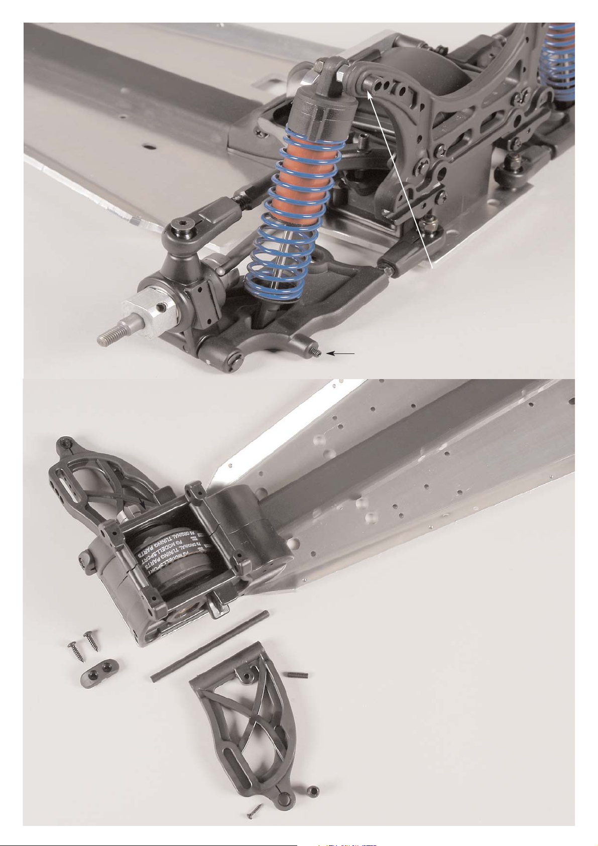
1. Push the rear axle cover between the left
and right rear axle mounts and fix it with the
alloy connection brace, M4x20 pan-head
screw and disk Ø4,3.
2. Disassemble the rear lower wishbone with
stabilizer from your 2WD model (stabilizer
only in Monster/Stadium models).
3. Fix the rear lower wishbones to the front
ball-and-socket joints using M5x30 counter-
sunk screws and 4 disks Ø5,3 (between ball-
and-socket joints and alloy chassis), then fix
all with M5 stop nuts to the alloy chassis.
Now fasten the rear ball-and-socket joints
with M5x25 countersunk screws and M5
stop nuts to the alloy chassis. Make sure the
mounted wishbones can be moved easily up
and down.
Alloy chassis
approx. 38mm
approx. 37,5mm
Screw
M5x25
Screw
M5x30
Screw
M4x20
Disk Ø5,3
Disk
Ø4,3
Rear lower
wishbone
Alloy connec-
tion brace
Stabilizer
5mm
Rear axle cover
Plastic brace for
stabilizer only for
Monster/Stadium
Ball-and-
socket joint
Adjusting screw
r/l 32mm
Stop nut M5
Position 8
Parts are in
bag D
All metric screws need to be secured with thread lock fluid.
Rear axle mount
right
Rear axle mount
left
Position 9
Parts are in
bag D
4. Impress the stabilizer 5mm (only for Monster/Stadium
models) in the plastic braces for stabilizer.
Adjust the setting screws
corresponding to your
existing model.

Stabilizer 5mm only in
Monster/Stadium version
Retaining
washer Ø5
Rear lower
wishbone pin
Rear driving
shaft
Disk Ø4,3
Rear damper
plate 4WD
Rear axle
mount left
Rear upright
left
Screw
4,2x9,5
Screw
4,2x22
Rear lower
wishbone
1. Mount the 4WD damper plate rear to the left and right
rear axle mounts using 4,2x22 pan-head screws.
2. Push the stabilizer (only Monster/Stadium models) into
the rear damper plate and fasten it with 4,2x9,5 pan-head
screws and disks Ø4,3.
3. Disassemble rear uprights, rear driving shafts and rear
lower wishbone pins from your existing 2WD model and
impress them in the rear lower wishbones as described in
position 10+11. Secure the wishbone pins with Ø5 retai-
ning washers.
Position 10
Parts are in
bag D
Position 11
Parts are in bag D

Adjusting clips
Retaining
washer Ø5
Rear upper
wishbone pin
Headless pin
M5x25
Left upright
Rear damper
plate
Rear wishbone
thread rod
M10/M8 84mm
Rear upper
wishbone
Ball-and-socket joint
Screw
M5x35
Baustufe 14
Teile sind in
Beutel
Position 12
Parts are in
bag D
Steel ball
10x13
Disk Ø5,3
Make sure the driving shaft has not
more than 2-3mm clearance in horizon-
tal position. Adjust the adjusting screws
of the rear axle correspondingly.
According to the toe-in
adjustment the upper
wishbone needs to be shim-
med by adjusting clips.
approx. 77mm
approx. 6mm
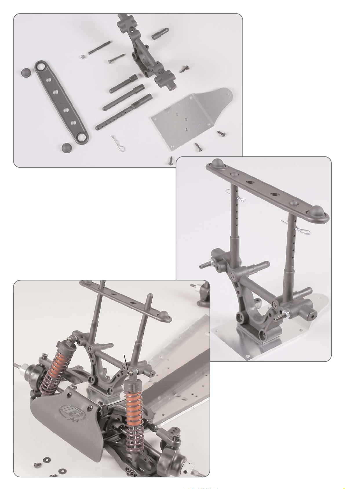
1. Disassemble the rear upper wishbone pin and the
ball-and-socket joint with steel ball from your existing
2WD model.
2. Screw the rear wishbone thread rods M10/M8 84mm into
the rear upper wishbones and in the ball-and-socket joints
to the size of approx. 77mm.
3. Fix the completely mounted rear upper wishbones at
the rear axle mounts by using wishbone pins, then
mount the rear damper plate. Secure the wishbone pins
with Ø5 retaining washers.
4. Push two adjusting clips each in the rear upper
wishbone pins in the front between rear axle mounts
and rear upper wishbones, then push one adjusting
clip each in the rear upper wishbone pins in the rear
between rear damper plate and rear upper wishbones.
5. Fix the ball-and-socket joints with steel
ball (steel ball collar must face the upright)
at the uprights using M5x35 countersunk
screws and disks Ø5,3, see position 12+13.
6. Screw M5x25 headless pins from above
into the rear upper wishbones (rebound stop
travel).
Disk
Ø5,3
Screw
M5x35
Position 13
Parts are in
bag D
Make sure the rear wishbones
can be moved easily up and
down.

O-ring
4x2
Damper fixing
short
Lower shock
absorber locking B
Lower shock
absorber locking A
Damper piston
rod long
Mounting of rear shock absorbers Marder/Baja
1. Mount o-rings 13x2,5 on the top of shock absorber locking M5 and lower
shock absorber locking A (position 14/14a).
2. Push retaining washer Ø3,2 in the first slot of the long damper piston
rod, then mount the damper piston with the recess facing towards the
retaining washer and fix it with a second retaining washer Ø3,2 (position
14b).
3. Press the lower shock absorber locking B (with the flat side facing the
damper piston), two o-rings 4x2 and upper shock absorber locking A
(with the thread facing the damper piston) on the long damper piston
rods.
4. Screw the short damper fixing on the thread of the long damper piston
rod until the thread is no longer visible. Now press it in the shock absor-
bers housing and screw it tight (position 14b).
5. Pull out the damper piston rod completely and fill the shock absorber
housing with oil to the start of thread. Now slide the damper piston rod
slowly several times in and out the shock absorber housing so that the
air bubbles in the oil will come upwards. If no longer air bubbles appear,
push the damper piston rod slowly into the shock absorber housing until
there are only approx. 5mm visible of the piston rod (position 14c). Then
screw the upper shock absorber lockings M5 on the shock absorber
housings (position 14d).
6. Mount one narrow and one wide damper collet each and a blue dam-
per pressure spring on the shock absorber housings and secure them
with the spring collars (Position 14e).
Mounting of front shock absorbers Marder/Baja
1. Dismount the rear shock absorbers from your existing 2WD model and
disassemble damper pressure springs, spring collar, damper fixings and
damper collets.
2. Screw the short damper fixings on the thread of the damper piston
rods until the thread is no longer visible.
6. Mount two narrow damper collets and a violet damper pressure spring
on the shock absorber housings, secure them with the spring collars
(position 14e).
Monster/Stadium
Retaining
washer Ø3,2
Mounting of shock absorbers Monster/Stadium
1. Mount the o-rings 13x2,5 on the upper shock absorber lockings M5 (positi-
on 14).
2. Dismount four shock absorbers from your existing 2WD model ans disas-
semble damper pressure springs, spring collar, damper fixings and damper
collets.
3. Screw two long and short damper fixings each on the thread of the
damper piston rod until the thread is no longer visible.
4. Dismount the upper shock absorber lockings M4, remove the oil from
the shock absorbers.
5. Pull out the damper piston rod completely and fill the shock absorber
housing with oil to the start of thread (position 14c). Now slide the dam-
per piston rod slowly several times in and out the shock absorber hou-
sing so that the air bubbles in the oil will come upwards. If no longer air
bubbles appear, push the damper piston rod slowly into the shock absor-
ber housing until there are only approx. 5mm visible of the piston rod.
Then screw the upper shock absorber lockings M5 on the shock absor-
ber housings (position 14d).
6. Mount each two narrow damper collets, one violet damper pressure
spring on the shock absorber housings with the long damper fixings and
secure with spring collars. Now mount each two wide damper collets,
one blue damper pressure spring on the shock absorber housings with
the short damper fixings and secure with spring collars (position 14f).
Rear damper
mounted
Rear damper
mounted
Front damper
mounted
Front damper
mounted
Hint: Slightly lubricate the o-rings with
silicone oil when mounting. If you use
the FG mounting tool 06853 + 06854,
the mounting of the shock absorbers
will be eased considerably.
Position 14
Parts are in
bag E
Position 14f
Position 14d
Parts are in
bag E
Position 14e
Position 14c
Parts are in
bag E
Position 14b
Parts are in
bag E
Position 14a
Parts are in
bag E
Mount o-ring 13x2,5
on the top shock
absorber locking.
Mount o-ring 13x2,5
on the lower shock
absorber locking.
Fill up with oil
to the start of
thread.
Damper piston
Push the piston
rod in, then
unscrew the
shock absorber
locking at the
top.
Marder/Baja
Screw
2,9x13
Screw
4,2x16
Guide for
stabilizer
Headless
pin
M5x16
Steel ball
Front lower
wishbone pin
Front lower
wishbone
Position 16
Parts are in
bag F
Hint: In order to withdraw the front lower wishbone
pins, screw an M4 screw into the threaded hole of
the front lower wishbone pins.
A clearance of the steel ball in the front lower
wishbone can be adjusted with the 2,9x13 screw.
Screw
M5x25
Nut
M5
Rear shock absor-
ber mounted
Stop
nut M5
Position 15
Parts are in
bag E
Rear damper
plate
Screw M5x25 cylinder screws into the rear
damper plate and counter with M5 nuts,
then fix the top of the shock absorber with
M5 stop nuts. Don’t tighten the stop nut.
All metric screws need to be secured
with thread lock fluid.
Front axle
housing left
Front axle
housing
right
Mount the rear shock absorbers to the rear
lower wishbones by using M4x30 headless
pins.
1. Screw the headless pin M5x16 from the
bottom into the front lower wishbone until
approx. 2mm thread are visible.
2. Disassemble the steel balls from the front axle of your exi-
sting 2WD model and push them into the front lower wishbo-
nes, then screw in the 2,9x13 pan-head screws.
3. Insert the front lower wishbones in the front axle housings, then
push the front lower wishbone pins with threaded hole towards
the front in the front axle housings and press them through the
pre-assembled front lower wishbones. Make sure the wishbones
can be moved easily up and down.
4. Impress the stabilizer guide as
locking device for the front lower
wishbone pins into the left and right
front axle housings and fix it using
4,2x16 pan-head screws.

Front lower
wishbone
Diff. dri-
ving axle
Adjusting
clips
Headless
pin
M5x25
Headless pin
M6x6
Front upper
wishbone
Front wishbone
thread rod
M10/M8 66mm
Front upper
wishbone
pin
Disk
Ø5,3
Disk
Ø5,3
Disk
Ø5,3
Disk
Ø8,4
Screw
M5x30
Screw
M5x30 Square wheel
driver 14mm
Front dri-
ving shaft
Front
driving
axle
Position 18
Parts are in
bag F
Steel
ball
1. Impress mounting nuts for front uprights from the
inside into the left and right uprights.
2. Push the ball bearing 17x26x7 from the inside into
the left and right upright.
3. Disassemble the ball bearing 8x22x7 from the
upright of your existing 2WD model and push it into the
front upright 4WD.
Position 17
Parts are in
bag F
Position 19
Parts are in
bag F
Front axle
housing
Front upright
4WD left
Front upright
left
Front upright
4WD left
Front upright
4WD right
Fixing nut for
front upright
Fixing nut for
front upright
Ball bearing
17x26x7
Ball bearing
8x22x7
Screw
M5x30
approx. 7,5mm
approx.19,5mm
Disk
Ø5,3
Make sure the driving shaft has not more than 2mm
clearance in horizontal position. Corresponding to the
adjustment of the upper wishbone (camber) you have
to mount or dismount enclosed steel disk Ø8,4 bet-
ween diff. axle and ball bearing.
1. Screw the front wishbone thread rods M10/M8
66mm into the front upper wishbones, then turn
the ball-and-socket joints on the front wishbone
thread rods M10/M8 66mm.
2. Dismount the steel balls from your existing
2WD model and press them into the ball-and-
socket joints.
3. Press the front upper wishbone pins through
the pre-assembled front upper wishbones into the
front axle housings as described in position 19.
Fix the front upper wishbone pins with Ø5 retai-
ning washers.
4. Withdraw the diff. driving axles from the front
differential and press them with disk Ø8,4 in the
front differential again.
5. Push the front driving axles into the pre-assem-
bled left and right uprights. Dismount square
wheel driver from your existing 2WD model and
mount it on the faces of the front driving axles
with the crank facing the bearing.
Ball-and-socket joint
Disk
Ø5,3
Mount the left and right
uprights to the lower wishbo-
nes and to the ball-and-socket
joints of the upper withbones
using Ø5,3 disks between
steel ball, screw and uprights.
At the same time mount the
driving shaft between front
driving axle and diff. driving
axle.
Retaining
washer Ø5
Impress four adjusting clips each in the
front between front axle housing and front
upper wishbones into the front upper
wishbone pins.
Screw the M5x25 headless
pins from above into the
front upper wishbones.
approx..49,5mm

Marder/Baja Buggy Position 23
Parts are in
bag G
Stop
nut M4
Disk
Ø4,3
Front bumper
Screw
M4x8
Screw
4,2x16
Screw M4x14
Marder
Baja Buggy
Baja Buggy
Position 20
Parts are in
bag G
Position 21
Parts are in
bag G
Position 22
Parts are in
bag G
Baja Buggy Position 20+21
1. Fix the front shock mount 4WD to
the reinforcing plate for the front axle
by using M4x16 countersunk screws,
Ø4,3 disks and M4 stop nuts.
Disassemble countersunk screw
M4x25 and M4 nut from the shock
mount of your existing 2WD model and
mount them at the front shock mount
4WD.
2. Mount the plastic fixing plate with
brake guide rail and alloy distances
between brake guide rail and reinfor-
cing plate to the reinforcing plate for
the front axle using M4x30 cylinder
screws, disks Ø4,3 and M4 stop nuts.
Marder Position 22
1. Fix front shock mount 4WD to the reinforcing plate
for the front axle using M4x16 countersunk screws,
disks Ø4,3 and M4 stop nuts.
Dismount countersunk screw M4x25 and M4 nut from
the shock mount of your existing 2WD model and
mount them in the 4WD shock mount.
2. Cover the rear bore holes of the reinforcing plate for
the front axle with an adhesive tape to prevent a con-
tamination of the gearwheel drive.
Marder/ Baja Buggy Position 23
1. Fix the assembled reinforcing plate for the front
axle on the front axle carriers using 4,2x13 pan-head
screws.
2. Mount the front shock absorbers at the front lower
wishbones using M4x14 cylinder screws, then fix the
top of the shock absorber with M4 stop nuts.
3. Assemble the front bumper with M4x8 pan-head
screws and Ø4,3 disks to the alloy chassis and with
4,2x16 pan-head screws at the front axle carriers.
Stop nut M4
Stop nut M4
Adhesive
tape
Reinforcing plate
for front axle
Plastic fixing
plate
Alloy
distance
Nut
M4
Nut
M4
Front shock
mount 4WD
Brake
guide
rail
Disk
Ø4,3
Disk
Ø4,3
Disk
Ø4,3
Screw
4,2x13
Screw
4,2x13
Screw
4,2x13
Screw
M4x16
Stop nut
M4
Reinforcing brace
for front axle
Front shock
mount 4WD
Disk
Ø4,3
Screw
M4x16
Screw
M4x25
Screw
M4x25
Screw
M4x30
Monster/Stadium
Monster/Stadium
Monster/Stadium
Position 24
Parts are in
bag G
Position 25
Parts are in
bag G
Position 26
Parts are in
bag G
Monster/Stadium Position 26
1. Fix the assembled reinforcing plate for front axle
on the front axle carrier using 4,2x13 pan-head
screws.
2. Mount the front shock absorbers to the front lower
wishbones with M4x14 cylinder screws, then fix the
shock absorbers at the top with M5 stop nuts.
3. Assemble the front bumper at the alloy chassis
using M4x8 pan-head screws and disks Ø4,3, then fix
it with 4,2x16 pan-head screws at the front axle car-
riers.
Stop
nut M5
Front bumper
Disk
Ø4,3
Screw
4,2x13
Screw
4,2x13
Screw
4,2x16
Screw
4,2x16
Screw
4,2x32
Screw
M4x8
Screw
4,2x16
Screw M4x14
Front shock
mount 4WD
Reinforcing plate for
front axle
Body support
Body mount short,
80mm, adjustable
Body clip
Dampening rubber
for body support
Nut M5
Headless pin
M5x45
Plastic part for
reinforcing plate
Monster/Stadium Position 24-25
1. Mount front shock mount 4WD to the reinforcing plate for front axle
using 4,2x16 countersunk screws.
2. Dismount the plastic parts for reinforcing brace from the shock mount of
your existing 2WD model and fix them to the front shock mount 4WD by
using 4,2x32 countersunk screws (position 25).
3. Screw the headless pins M5x45 from the front into the front shock
mount 4WD until they are flush with the rear side of the shock mount.
Then counter the headless pins witrh M5 nuts.
4. Disassemble the adjustable body mounts from the shock mount of
your existing 2WD model and mount them to the front shock mount
4WD by using 4,2x16 pan-head screws.
5. Fix the body clips in the adjustable body mounts as described in position
25 and press on the body support. Use the body clips and the body sup-
port from your existing 2WD model.
Screw
4,2x32
Nut M5
Headless
pin M5x45
Plastic
mount
Position 30
Parts are in
bag H
Position 31a
Parts are in
bag H
Position 30b
Parts are in
bag H
Position30c
Parts are in
bag H
Position 30d
Parts are in
bag H
Position 31
Parts are in
bag H
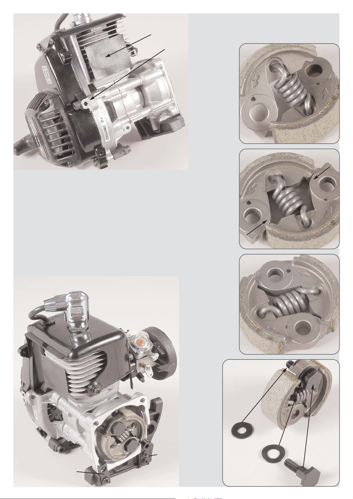
1. Disassemble the complete engine from your existing 2WD model.
Remove muffler, airfilter, gearplate and clutch. Make sure no dirt gets in the outlet port of the engi-
ne.
2. Dismount the clutch spring by twisting the clutch blocks.
3. Mount new clutch spring as described in position 30a-30c.
4. Now disperse the clutch blocks slightly until the clutch blocks lay straight parallel again, positi-
on 30b.
5. Push the clutch blocks on top of each other by using tongs or a vice, until they lock. Position
30c.
6. Push the shaft washers on the dowel screws for the clutch blocks and press them into the
clutch blocks from the side with the arrows (engine running direction). Fix them on the clutch
block carrier using 6x15x1 disks. Position 30d and 31.
7. Disassemble steel fixing plates and ball bearing 10x19x7 from the existing 2WD parts and
mount them to the large plastic mount 4WD.
8. Now mount the large plastic engine mount 4WD with the long and short steel fixing plates on
the engine using 4,2x13 pan-head screws as described in position 31.
Hint: If you use the FG piston punching pin Item N°. 08542 the mounting of the clutch will be con-
siderably simplified.
Clutch blocks
Clutch spring
Dowel screw for
clutch blocks
Plastic engine
mount large
4WD
Shaft washer
Driving direction
Disk
6x15x1
Screw
4,2x13
Screw
4,2x13
Steel fixing plate long
Steel fixing plate short
Ball bearing
10x19x7
1. Cover the outlet port of the engine
with an adhesive tape.
2. Saw off the housing part
with an metal hand saw, see
also illustration in position 31.
All metric screws need to be secured
with thread lock fluid.

Position 33
Parts are in
bag I
Steel gearwheel
15 teeth only for
Monster models
Headless
pin
M5x5
Headless
pin
M5x5
Brake
square
Clutch bell
Plastic
gearwheel
Gear
shaft
4WD
Retaining
washer Ø7
Retaining
washer Ø7
Gear
plate
Shim ring
10x16x1
Position 32
Parts are in
bag I
3. Push the gear shaft 4WD through the ball bearing of the large
plastic engine mount 4WD and re-assemble the gear plate at the
clutch flange using M6x40 cylinder screws and Ø6,4 disks.
4. Press steel gearwheel 14 teeth on the gear shaft 4WD as pic-
tured and fix it on the surfaces of the gear shaft 4WD using
M5x5 headless pins, secure with M6x16 countersunk screw and
use a high-strength screw retention (Position 32+34).
Plastic engine
mount large
4WD Gearwheel
cover gear
Clutchl flange
Basic
body
Filter cover
Screw
4,2x13
Screw
4,2x13
Screw
4,2x13
O-ring for airfilter
adapter
Airfilter
adapter
Foam filter Screw
4,2x16
Screw
M6x40
Screw
M6x16
Steel
gearwheel
14 teeth
Headless
pin
M5x5
Gear
shaft
4WD
Disk
Ø6,4
1. Remove the adhesive
tape from the outlet port of
the engine and re-assemble
muffler with muffler gasket
from your existing 2WD
model.
Mount the gearwheel cover at the large plastic
engine mount 4WD using 4,2x13 pan-head
screws as described in position 32+34.
Insert the o-ring for the airfilter
adapter in the basic body and
fasten it to the airfilter adapter
using 4,2x13 countersunk screws.
Press the oiled foam filter of your
existing 2WD model on the basic
body and fix it with filter cover and
4,2x16 countersunk screw.
Gear
plate
Hint: Rinse the existing foam filter (if it is dirty) with rinsing water,
let it dry and oil it again. To oil the foam filter knead it in a plastic
bag with FG filter oil Item N°. 06441 repeatedly.
2. Remove retaining washer Ø7 of the gear shaft from the plastic
gearwheel. Dismount headless pin M5x5 of the brake square and pull
out the 2WD geart shaft from the gear plate. Then press the 4WD
gear shaft through the brake square, gear plate, shim ring 1x16x1
and plastic gearwheel and secure it with retaining washer Ø7. Mount
brake square backlash-free on the surface of the gear shaft 4WD
using the headless pin M5x5.
Only for Monster models:
Dismount steel geawheel 16 teeth.
Mount steel gearwheel 15 teeth on the clutch bell and
secure with Ø7 retaining washer.
Tighten the steel gearwheel 15 teeth backlash-free on the
surfaces of the clutch bell using headless pins M5x5.
Position 34
Parts are in
bag I
Make sure that driving gearwheels, driving shafts
a.s.o. can be turned easily without any resistance.

Screw
4,2x32
Disk Ø4,3
Rear axle
mount left
Alloy connec-
ting brace
Plastic engi-
ne mount
large 4WD
Position 35
Parts are in
bag I
Position 36
Parts are in
bag I
1. Insert the complete engine in the
alloy chassis and fasten it with
4,2x32 pan-head screw and disk
Ø4,3 through the rear axle mount.
Do not tighten the 4,2x32 pan-head
screw yet, see also position 36a.
2. Fix the pre-assembled engine
using 4,2x16 countersunk screws
and engine fixing disks from
underneath on the alloy chassis.
Screw
4,2x32
Disk
Ø4,3
Screw
4,2x16
Screw
4,2x16
Screw
4,2x16
Alloy chassis
Tank mount
Tank complete
Tank base
Engine fixing
disk
5. Tighten the 4,2x32 pan-head
screws after setting the engine fixing
screws tight.
6. Install the fuel pipes as pictured,
shorten them if necessary.
3. Dismount tank from your existing 2WD
model. Fix the tank (tank cap facing the right
side) with tank mount on the tank base using
4,2x16 countersunk screws (longer side of tank
base must face the right side).
4. Mount the tank assembled on tank base on
the alloy chassis using 4,2x16 countersunk
screws.
All metric screws need to be secured
with thread lock fluid.
Position 36a
Parts are in
bag I

Screw
2,9x13
Plastic rc-plate
4WD
Battery mount with
receiver battery
Flexible aerial
Receiver
box
Body clip
Bolt for bat-
tery mount
Collar disk for
rc-plate 4WD
Steering servo
Gas/brake
servo
All metric screws need to be secured
with thread lock fluid.
Position 37
Parts are in
bag J
Position 38
Parts are in
bag J
Position 39
Parts are in
bag J
Position 40
Parts are in
bag J
Servo
arm
1. Dismount the rc-plate from your existing 2WD
model, remove battery mount, servos and receiver
box.
2. Mount the throttle/brake servo and the stee-
ring servo in the plastic rc-plate 4WD as descri-
bed in position 37.
3. Fix the receiver box to the plastic rc-plate
4WD using 2,9x13 pan-head screws, connect
the servo cables, battery cables to the receiver
again and check the function. Now stow the
receiver and the rest of the servo cables in the
receiver box, lead the aerial cable of the receiver
in the flexible aerial.
4. Press the collar disk for the 4WD rc-plate into
the plastic rc-plate 4WD.
5. Mount the bolts for the battery mounts to the
plastic rc-plate 4WD using 2,9x13 pan-head
screws. Fix the battery mount with receiver bat-
tery with body clips to the bolts.
6. Now press the servo arm back on the steering
servo as described in position 38 and fix it with
enclosed screw. The servo arm should be in a
90-degree position to the steering servo at neu-
tral position of the radio control, change the
position of the servo arm correspondingly.
Screw
2,9x13
Screw
2,9x13
Receiver
box
Plastic rc-plate
4WD
Servo saver
axle
Track rod
mounted
Joint
ball
Servo rods
mounted
Servo saver
mounted
Rods M4x51
Tension sleeve for
servo saver
Servo
saver
Part B
Servo
saver
Part A
Servo
saver
spring
Nut M10 for
servo saver
Screw
M5x10
Screw
M4x20
Screw
2,9x19
Stop nut
M4
Ball bearing
7mm
Steel ball
7mm
Collar disk for
rc-plate 4WD
6. Dismount the servo rods from your existing 2WD model
and remove the ball-and-socket joints from the linkage.
7. Screw the ball-and-socket joints 7mm on the rods M4x51
and press the steel balls 7mm into the ball-and-socket joints.
8. Fix the servo rods (collar of the steel ball must face the
servo saver) at the inner hole of the servo saver using 2,9x19
pan-head screws as pictured.
4. Disassemble the track
rods of your existing 2WD
model.
5. Mount the track rods
(collar of the joint ball
must face the servo saver)
to the servo saver by
using M4x20 cylinder
screws and M4 stop nuts. 1. Impress the tension sleeve for servo saver
from above through servo saver part B and
servo saver part A.
2. Mount the servo saver spring with the
M10 nut on the thread of the tension slee-
ve and check on free movement.
3. Lubricate the servo saver axle slightly
and press it from the top into the tension
sleeve for servo saver. Secure the servo
saver axle with an M5x10 pan-head
screw. Use screw retention lacquer.
Hint: Fill the bottom part of the receiver box
with some foam to protect the receiver
against vibrations.
approx. 108mm

3. Switch on the remote control system, set the trimming of
the steering to central position. Adjust the servo saver in
centre to the chassis. First mount one servo rod to the
servo arm of the steering servo using a 2,9x16 pan-head
screw, then mount the second servo rod. Both servo rods
should be adjusted in the same length. You should be able
to mount both servo rods easily and without any resistance
to the servo arm of the steering servo using 2,9x16 pan-
head screws, position 41-43.
4. Mount the track rods to the front uprights by using M4x20
cylinder screws, Ø4,3 disks and M4 stop nuts as described
in position 43.
Position 41
Parts are in
bag J
Position 42
Parts are in
bag J
Position 43
Parts are in
bag J
Screw
2,9x16
Steering servo
Servo rods
Alloy chassis
Plastic rc-plate 4WD
Plastic rc-
plate 4WD
Servo
saver
Servo
saver
Screw
4,2x16
Screw
M4x20
Screw
M4x20
Stop nut
M4
Stop nut
M4
Screw
4,2x16
Disk
Ø4,3
Disk
Ø4,3
Screw
M5x16
Screw
M5x16
Disk
Ø5,3
Disk
Ø5,3
Track rod
Track rod
Front upright
left
Front upright
left
Front axle
stiffening
Front axle
stiffening
All metric screws need to be secured with thread lock fluid.
1. Mount the plastic rc-plate 4WD underneath the front axle stif-
fening to the alloy chassis using 4,2x16 countersunk screws.
2. Now mount the servo saver underneath the plastic rc-plate
4WD by using M5x16 pan-head screw and Ø5,3 disk as pictu-
red. Use screw retention lacquer.
Dirt, but also longer downtimes can
affect the function and free move-
ment of the servo saver. Therefore we
recommend to spray some penetra-
ting oil between tension sleeve and
servo saver part A+B. Then press ser-
vo saver part A downwards against
the spring and check the function. If it
does not function smoothly you have
to dismount and clean the part.
A stiff servo saver can cause a servo
damage.

1. Mount the throttle rods to the carburetor arm using
collets and M3x3 headless pins as described in positi-
on 45. Keep some clearance between the collets and
the carburetor arm. Make sure the carburetor arm can
be easily moved and does not jam.
2. Push the M3x25 pan-head screw from the bottom
into the servo arm as described in position 46 and
secure it with an M3 nut. Screw on two M3 stop nuts
as distance. Switch on the remote control system and
set the trimming for throttle/brake in central position.
Press the servo arm on the the servo as pictured in
position 46 and fix it with enclosed screw.
3. Push the collet, pressure spring, throttle pivot post
and collet on the throttle rods. In doing so, press the
throttle pivot post on the M3x25 pan-head screw and
secure it with an M3 stop nut. Fix the collets using
M3x3 headless pins. See position 46.
Switch on the remote control system. Set the servo for
throttle/brake in central position. Now clamp the collet
to the throttle pivot post using an M3x3 headless pin.
Set the transmitter to full throttle position and check if
the carburetor arm opens completely.
Tipp: Do not tighten the M3 stop nut at the throttle
pivot post. The throttle pivot post and the throttle rods
must run smoothly, move easily and should neither
touch nor clamp in any position.
Throttle rods
Brake rods
Collet
Collet
Headless
pin M3x3
Headless
pin M3x3
Carburetor
arm
Position 44
Parts are in
bag K
Position 46
Parts are in
bag K
Steering servo
Throttle rods
Brake rods
Pressure spring
Throttle/brake
servo
Servo
arm
Nut
M3
Stop
nut M3
Stop
nut M3
Collet
Collet
Headless pin
M3x3
Headless
pin
M3x3
Screw
M3x25
Throttle pivot
post
Position 45
Parts are in
bag K

Position 48
Baustufe 50
Teile sind in
Beutel
Baja
Dämpferplatte
hinten 4WD
Roll bar
Screw
M4x8
Screw
M4x8
Alloy chassis
Schraube
4,2x13
Auspuffrohr
Screw
4,2x32
Schraube
4,2x22
Plastic brace
long
Kunststoff
strebe kurz
Spoilerhalter
Alloy side
plate left
Side body
mount
Alloy side
plate right
Halterung für
Auspuffrohr
Screw
4,2x16
Disk
Ø4,3
Scheibe
Ø4,3
Plastic
bush
4/6x5mm
Schraube
M6x75
Allloy distance
10x34
Disk Ø6,4
Cylinder screw
M6x75
Position 47
Parts are in
bag K
Screw
2,9x9,5
Screw
2,9x9,5
Screw
2,9x9,5
Alloy chassis Screw
4,2x16
Reinforcing brace
Plastic part for
reinforcing brace
Plastic part for
reinforcing brace
Reinforcing brace
Roll bar
Screw
4,2x32
3. Mount the roll bar to the alloy chassis
using 4,2x16 countersunk screws.
1. Dismount roll bar and reinforcing brace from your existing 2WD
model.
2. Mount the plastic parts for the reinforcing braces at the roll bar
again using 4,2x32 pan-head screws as pictured. Push the reinforcing
braces into the plastic parts for the braces at the front shock mount
and fix them using 2,9x9,5 pan-head screws.
Monster/Stadium models
Monster/Stadium models
1. Disassemble the left and right alloy side plates from your existing 2WD model and mount them to
the alloy chassis using M4x8 pan-head screws. Fix the left and right alloy side plates to the front
shock mount using 4,2x16 pan-head screws, Ø4,3 disks and plastic bushes 4/6x5.
2. Fasten the left alloy side plate with M6x75 cylinder screw, Ø6,4 disk and alloy distance 10x34.
3. Fasten the right alloy side plate with M4x45 cylinder screw, Ø4,3 disk and alloy distance 8x27.
4. Dismount the complete rear spoiler mount from your existing 2WD model and fix it at the rear shock
mount 4WD by using M4x20 cylinder screws and M4 stop nuts. Spoiler mount and rear body mounts
can differ for Hummer, Jeep and Beetle Pro models.
5. Mount the long plastic braces with 4,2x32 pan-head screws and roll bar.
If necessary file the side plates here slightly to
make sure the track rods do not pile while
steering. Treat the other side in the same way.
If necessary file the boring to a long slot.
Treat the other side in the same way. Mount exhaust pipe from your
existing 2WD model.
Table of contents
Other FG Modellsport Toy manuals


Popular Toy manuals by other brands


Fisher-Price
Fisher-Price GEO TRAX K3115 user manual

Fancy Foam Models
Fancy Foam Models IndoorDepron001 Assembly instructions

Jamara
Jamara Tiger Moth Instruction

Mattel
Mattel Roll Cage Tyco RC user guide

Thames & Kosmos
Thames & Kosmos DIG IT! DINOS GIANT DINOSAUR SKELETON KIT manual

PalPlay
PalPlay The House of Fun M780 Assembly instructions