Fiamm FET FG Series User manual

Installation and Operating Instructions
Technical Manual
Valve Regulated Lead Acid Batteries
AGM technology

This document and the confidential information it contains shall be distributed, routed or made available solely with written permission of FIAMM Energy Technology.
FIAMM Energy Technology S.p.A. reserves the right to change or revise without notice any information or detail given in this publication. Pag 1 / 12
FIAMM Energy Technology S.p.A Installation & Operating Instruction -Technical Manual Edition 03/2018 Rev.7
TABLE OF CONTENTS
INTRODUCTION ...................................... 2
1. CONSTRUCTION FEATURES .............. 2
1.1. Plates ............................................... 2
1.2. Containers........................................ 2
1.3. Separators........................................ 2
1.4. Electrolyte........................................ 2
1.5. Valves .............................................. 2
1.6. Terminal posts.................................. 2
1.7. Connections (where supplied)............ 3
1.8. Front Terminal Connections............. 3
1.9. Remote Venting System (RVS).......... 3
2. OPERATING FEATURES...................... 4
2.1. Capacity........................................... 4
2.2. Capacity in relation to discharge rate 4
2.3. Capacity range of FET AGM Lead
Acid Batteries............................................. 4
2.4. Capacity in relation to the temperature
4
2.5. Internal impedance and short circuit
current....................................................... 4
2.6. Service life........................................ 5
2.7. Gassing ............................................ 5
2.8. Operation of batteries in parallel....... 5
2.9. Open circuit voltage - State of charge 5
3. CHARGING........................................... 6
3.1. Floating charge................................. 6
3.2. Boost charge (Recharge following a
discharge)................................................... 6
4. BATTERY INSTALLATION.................. 7
4.1. Installation....................................... 7
4.2. Batteries installed into cabinet........... 7
4.3. Ripple .............................................. 8
4.4. Battery room requirements............... 8
5. SAFETY................................................. 8
5.1. Protective Equipment ....................... 8
5.2. Safety Precautions............................ 8
5.3. Battery Disposal ............................... 8
6. MAINTENANCE.................................... 9
6.1. Battery care...................................... 9
6.2. Cleaning........................................... 9
6.3. Voltage checks.................................. 9
6.4. Cell appearance................................ 9
6.5. Pilot Cell .......................................... 9
6.6. Periodic Inspections.......................... 9
7. APPLICABLE STANDARDS ..................9
8. BATTERY TEST...................................10
8.1. Service/Functional test....................10
8.2. Capacity test ...................................10
9. UNPACKING........................................11
9.1. Inspection .......................................11
9.2. Handling.........................................11
10. STORAGE .........................................11
10.1. Storage prior to installation..........11
10.2. Storage Conditions.......................11
10.3. Storage time / Temperature..........11
10.4. Storage / Recharge.......................11
11. VENTILATION (in accordance with EN
50272-2).......................................................12
11.1. Determination of openings............12
11.2. Forced ventilation........................12
11.3. Close vicinity to the battery..........12
This document and the confidential information it contains shall be distributed, routed or made available solely with written permission of FIAMM Energy Technology.
FIAMM Energy Technology S.p.A. reserves the right to change or revise without notice any information or detail given in this publication. Pag 2 / 12
FIAMM Energy Technology S.p.A Installation & Operating Instruction -Technical Manual Edition 03/2018 Rev.7
INTRODUCTION
In a high technological environment it is extremely
important to have a backup power source whenever
possible. In fact mains power failure could cause severe
losses and damages anytime.
FIAMM ENERGY TECHONOLOGY (FET) has been
developing throughout years of research and experience
several ranges of Absorbed Glass Batteries (AGM) to
ensure the best reliability and quality.
1. CONSTRUCTION FEATURES
The main construction features of FET AGM
batteries are shortly described in the below section.
1.1. Plates
Both positive and negative plates are of the flat pasted
type. The active material is made of a paste of lead
oxide, water, sulphuric acid and other materials needed
to obtain the performances and stability required
throughout the battery life. The grids are made of a high
quality lead alloy with calcium and tin which assures
good resistance against corrosion
1.2. Containers
Battery cases and lids are made of a type of ABS which
complies with American Standards UL 94 (per specific
models class V-0 and with IEC 707, method FV0). This
material is shock resistant and flame retardant. They are
also designed to fully withstand the internal pressure
variations during battery operation. This is further
ensured by reinforced container walls and lids. Handles
have been designed for some batteries into the lids to
facilitate handling.
1.3. Separators
The separators are made of glass microfiber mats by a
special process which results in a high porosity with very
small pore diameters to ensure maximum oxygen
diffusion while maintaining high plate utilization and
low internal resistance. The plates are completely
wrapped by the separator and the electrolyte is
completely absorbed in the separator and plates. By this
method, the shedding of active material which during the
battery life causes shorting with flooded battery
construction is avoided.
1.4. Electrolyte
The electrolyte is sulphuric acid of 1.3 sp. gr. at 20°C
with same purity characteristics as other types of high
quality lead acid batteries.
1.5. Valves
Each cell has a one way valve to permit the release of
gases from the cell whenever the internal pressure
exceeds the fixed safety value. The valve is rated at
0.15~0.30 atmospheres (15~30 kPa).
1.6. Terminal posts
Suitable threaded post designs (‘female’ or ‘faston’ pole)
with solid connectors are provided to ensure low ohmic
losses. Posts to lid seals are designed to prevent leakage
over a wide range of internal pressures and conditions of
thermal cycling. Intercell connections in the FET
multicell AGM battery design are electrically welded
through the cell walls to minimize the internal
impedance while maintaining complete separation of the
individual cells.
Special plastic terminal caps are provided for
transportation assuring a protection against short circuit
during transportation.
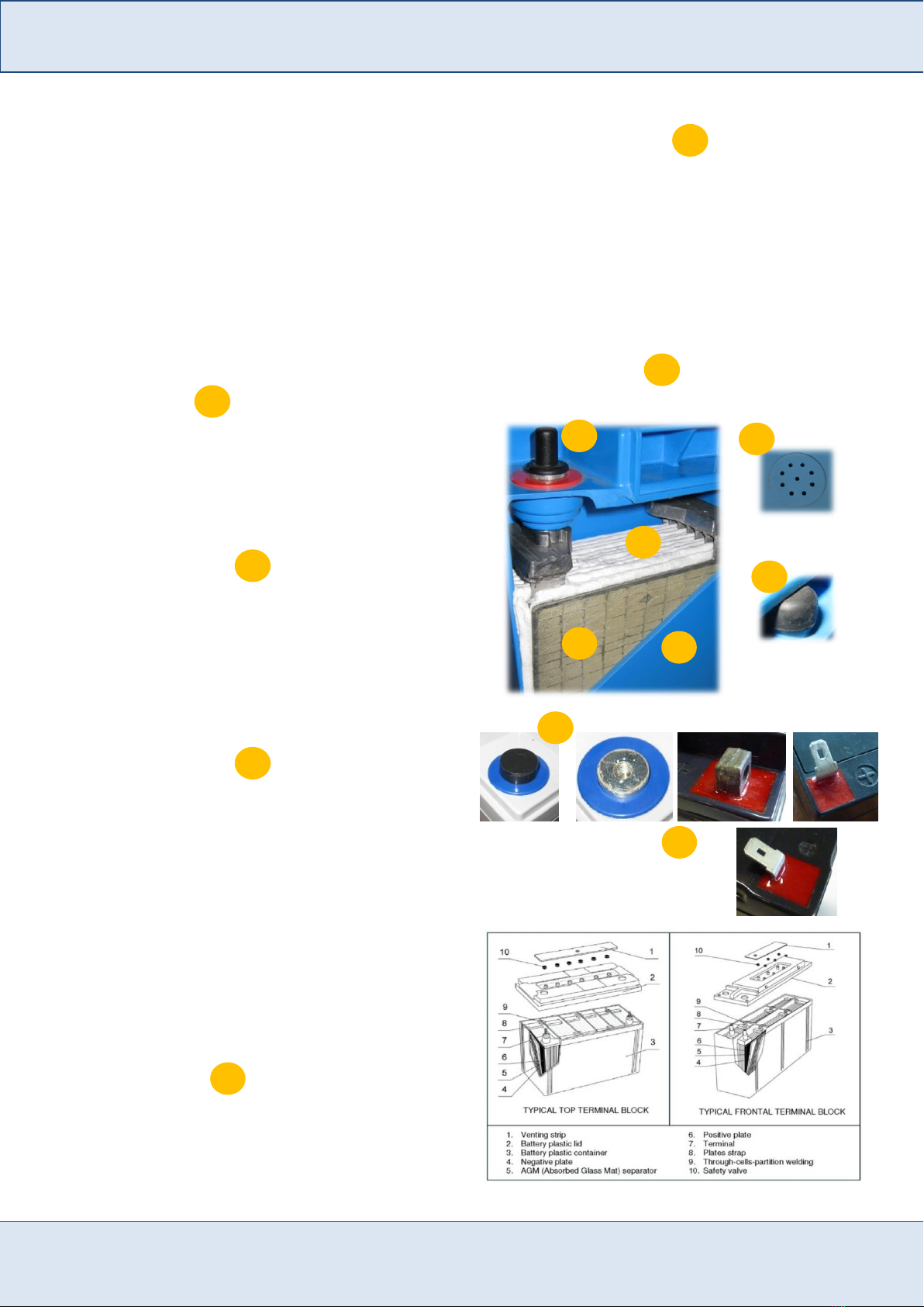
Cutaway drawing of FET AGM cell
Female (Bolt) terminal
A
B
C
E
E
D
D
C
A
B
F
E
D
F

This document and the confidential information it contains shall be distributed, routed or made available solely with written permission of FIAMM Energy Technology.
FIAMM Energy Technology S.p.A. reserves the right to change or revise without notice any information or detail given in this publication. Pag 3 / 12
FIAMM Energy Technology S.p.A Installation & Operating Instruction -Technical Manual Edition 03/2018 Rev.7
1.7. Connections (where supplied)
Suitable solid connectors are made of tin or lead
plated copper; suitable insulated plastic covers
are made of ABS -V0
TOP TERMINAL CONNECTION is mainly used for
FET battery range SLA –FLB as well
1.8. Front Terminal Connections
Suitable solid connectors made of copper thin or lead
plated and covers made of ABS are provided to make a
proper installation between blocs. Designed for FET
front terminal range FIT using a special “L “ clamp
SOLID CONNECTOR
COVER
“L” CLAMP
1.9. Remote Venting System (RVS)
Most of FET AGM batteries are designed with an
optional central degassing system on the top lid
covering sheet. So if batteries need to be installed in a
totally sealed cabinet, it is advisable to use the remote
venting system available from the manufacturer to
conduct any gas from the batteries to the outside of
the cabinet itself.
RVS –front side used for FIT
range
RVS –top side
used for SLA / FLB / FIT range
1
2
1
1
2
1
2
2
1
1
2
3
3
2
4
5
4
5
From 5 to
10 mm.

This document and the confidential information it contains shall be distributed, routed or made available solely with written permission of FIAMM Energy Technology.
FIAMM Energy Technology S.p.A. reserves the right to change or revise without notice any information or detail given in this publication. Pag 4 / 12
FIAMM Energy Technology S.p.A Installation & Operating Instruction -Technical Manual Edition 03/2018 Rev.7
2. OPERATING FEATURES
2.1. Capacity
The battery capacity is rated in ampere hours (Ah) and
is the quantity of electricity which it can supply during
discharge. The capacity depends on quantity of active
materials contained in the battery (thus on dimensions
and weight) as well as the discharge rate, and
temperature, and minimum voltage.
The nominal capacity of FET batteries refers to the 10
(or 20) hrs discharge rate (indicated with C10 or C20)
with constant current at 20°C to 1.80 (or 1.75 per C20)
volt per cell.
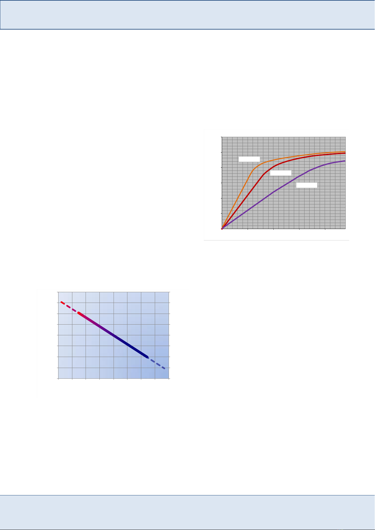
Fig. 1: Typical discharge curves for FET AGM batteries (FIT range)
2.2. Capacity in relation to discharge rate
The available capacity of all lead acid batteries depends
on discharge rate (discharge current); this is due to
internal electrochemical process and type of
construction (i.e. type of positive plate).
Fig. 2: Average available capacity versus discharge rates for FET AGM
batteries
2.3. Capacity range of FET AGM Lead Acid
Batteries
FET Battery
range
Battery Capacity
[Ah]
FG
from 1.2 to 70
FGC
from 12 to 42
FGH
from 5 to 18
FGHL
from 5 to 12
FGL
from 17 to 205
FIT
from 40 to 195
FHT
from 95 to 180
SLA
from 25 to 2000
FLB
from 26 to 235
2.4. Capacity in relation to the temperature
The capacity available from a battery, at any
particular discharge rate, varies with temperature.
Batteries which have to operate at temperatures
different from the nominal (20°C) need a higher or
lower capacity as per the factor indicated in the
following graph (required capacity has to be divided
by the correction factor stated in the graph).
Fig. 3: Capacity Correction factor versus temperature for a 10 hours
discharge rate for FET Lead Acid AGM batteries
2.5. Internal impedance and short circuit
current
The internal impedance of a lead acid battery is a
direct result of the type of internal construction, plate
thickness, number of plates, separator material,
electrolyte sp. gr., temperature and state of charge.
The internal resistance and the short circuit current of
FET VRLA batteries at 100% state of charge and
20°C is indicated in the relative Product Sheet. These
values are calculated in accordance with IEC 60896
part 21/22.
Different instruments are available to detect the
internal resistance or impedance of lead acid
batteries. These instruments use a different way to
determinate these values. The values obtained from
9
9.5
10
10.5
11
11.5
12
12.5
13
0 1 2 3 4 5 6 7 8 9 10 11 12 13 14
Bloc Voltage (Volt)
hours
I=0,85C10
I=0,15 C10
I=0,1C10
I=0,27 C10
I=0,5C10
I=0,088C10
0
20
40
60
80
100
120
0 2 4 6 8 10
available capacity [%]
hours
0.4
0.5
0.6
0.7
0.8
0.9
1.0
1.1
1.2
Temperature correction factor
Temperature
15 -30 min. discharge rate
1-10 hours discharge rate
-20°C -10°C 0°C 10°C 20°C 30°C 40°C 50°C

This document and the confidential information it contains shall be distributed, routed or made available solely with written permission of FIAMM Energy Technology.
FIAMM Energy Technology S.p.A. reserves the right to change or revise without notice any information or detail given in this publication. Pag 5 / 12
FIAMM Energy Technology S.p.A Installation & Operating Instruction -Technical Manual Edition 03/2018 Rev.7
these instruments will be different to the values
stated in FET Product Sheet.
2.6. Service life
According to the main international standards a battery is
considered at the end of its service life whenever
delivering less than 80% of its nominal capacity. The
recommended operating temperature range is between
10°C to 30°C (FHT range peaks up to 45°C). FET
VRLA batteries can operate over a temperature range of
–20 to +50°C and higher; operation at temperature higher
than 20°C reduces life expectancy according to the graph
in figure 4.
Fig. 4: Expected service life vs. working temperature
2.7. Gassing
All Lead Acid Batteries emits gases during the charge
process. FET VRLA batteries have a high recombination
efficiency (>98%) and for cells operated at 20°C under
normal operating conditions venting is virtually
negligible. Laboratory test measurements show the
following gassing rates:
2 ml/Ah/cell/month at a float voltage of 2.27 V/cell
10 ml/Ah/cell/month at a recharge voltage of 2.40
V/cell.
The quantity of gas given off in the air (it basically
consists of 80-90% hydrogen) is very low and thus it is
clear that FET VRLA batteries can be installed in rooms
containing electric equipment with no explosion danger
or corrosion problems under normal conditions. In any
case these rooms or cabinets must have natural or forced
ventilation and not be fully sealed. Please refer to
“VENTILATION” for information on required air
exchange.
2.8. Operation of batteries in parallel
When the required capacity exceeds the capacity of a
single string of batteries, it is possible to connect more
strings in parallel paying attention to the following
guidelines:
in each string only cells or monoblocs of the same
type, model, manufacturing date and quantity
should be used;
a symmetrical layout of the batteries should be
designed (i.e. length and type of connector) to
minimize possible resistance variations;
the quantity of strings in parallel should be
reasonable in terms of layout and application.
Usually 4 strings could be connected in parallel.
However, depending on strings voltage and
cables length, a higher number of strings could be
safely connected to reach required total capacity.
2.9. Open circuit voltage - State of charge
The measurement of the open circuit voltage (battery has
to be disconnect from charger system for at least 24
hours) provides an approximate indication of the state of
charge of the cells.
Fig. 5: Approximate state of Charge versus Open circuit cell voltage
20 30 40 50
TEMPERATURE[°C]
0
20
40
60
80
100
120
BatteryLife(%)
1.95
2.00
2.05
2.10
2.15
0% 20% 40% 60% 80% 100%
Open Circuit Voltage [V/cell.]
State of Charge [%]
This document and the confidential information it contains shall be distributed, routed or made available solely with written permission of FIAMM Energy Technology.
FIAMM Energy Technology S.p.A. reserves the right to change or revise without notice any information or detail given in this publication. Pag 6 / 12
FIAMM Energy Technology S.p.A Installation & Operating Instruction -Technical Manual Edition 03/2018 Rev.7
3. CHARGING
In order to ensure the best protection against power
failures in any moment, it is necessary that batteries are
kept in the following conditions:
in float charging throughout all their standby period;
fully recharged soon after a discharge,
completely recharged after a discharge. Recharge as
soon as possible to ensure maximum protection
against subsequent power outages. Early recharge
also ensures the maximum battery life.
3.1. Floating charge
Floating battery systems are those where the charger, the
battery and the load are connected in parallel.
The "float" setting will maintain the battery in a fully
charged state with minimal water consumption.
The voltage recommended for float charge is 2.27 V at
20°C. The recommended float voltages to maximize the
battery life over the range of temperatures between -20
and +60°C are shown in the figure 6 or using the
formula: -2.5mV/cell/°C
The normal float current observed in fully charged FET
front terminal batteries at 2.27 VPC and a temperature of
20°C is approximately 0.3 mA/Ah. Because of the nature
of recombination phenomena, the float current observed
in the case of the FET front terminal batteries is normally
higher than that of vented batteries and is not an
indication of the state of charge of batteries.
Fig. 6 : Recommended Float Voltage at different temperatures
3.2. Boost charge (Recharge following a
discharge)
Boost charge has to be used to recharge a battery after a
discharge; it will restore the battery to a fully charged
state within a relatively short period of time. Use a
constant voltage 2.40 V/cell at 20°C with a maximum
current of 0.25 C10. However this recharge should be
limited to no more than once per month to ensure the
maximum service life of the battery. Temperature has to
remain lower than 35°C.
Fig. 7 : Recharge curves at 2.40 V/cell with different limit of current
-4
14
32
50
68
86
104
122
140
-20
-10
0
10
20
30
40
50
60
2.19 2.21 2.23 2.25 2.27 2.29 2.31 2.33 2.35
Tempearture [°F]
Temperature [°C]
Float Voltage [V/cell]
0%
20%
40%
60%
80%
100%
120%
0 5 10 15 20
Recharged Capacity [Ah]
Time [hours]
I=0.15 C10
I=0.10 C10
I=0.05 C10
This document and the confidential information it contains shall be distributed, routed or made available solely with written permission of FIAMM Energy Technology.
FIAMM Energy Technology S.p.A. reserves the right to change or revise without notice any information or detail given in this publication. Pag 7 / 12
FIAMM Energy Technology S.p.A Installation & Operating Instruction -Technical Manual Edition 03/2018 Rev.7
4. BATTERY INSTALLATION
All necessary precaution must be taken when working
with lead acid batteries as per electrical risk, explosives
gasses, heavy components, corrosive liquids. Use
insulated tools and wear protective equipment.
4.1. Installation
FET front terminal valve regulated recombination
batteries can be fitted on stands or into cabinets. FET
offers a wide selection of stands, from one tier/one row
to six tiers/three rows, to suit most applications. Cabinets
are available with or without circuit breaker and its
relevant compartment.
1. Avoid any impact or shock which could cause
breaking or micro fractures to container. Do not lift
cells by its terminals. Always lift the individual unit
from underneath, or by the build-in-lifting handles
2. Make sure that all cell jars and covers are thoroughly
clean and dry.
3. Synthetic cleaning cloths must not be used. Clean lids
and containers only with antistatic cotton cloths
soaked in a solution of mild soap and completely
“wrung” out.
4. Should the terminal posts have a white film on them,
lightly abrade their contact surfaces, using a
Scotchbrite pad or fine grit abrasive paper, to remove
any surface oxidation.
5. Do not lift cells by terminals; do not use terminals as
point of lifting during handling/installation process.
6. Place the single units at their correct position
according to the electrical layout.
7. In order to allow heat dissipation a minimum distance
of 5-10mm between cells/blocs is recommended; this
is normal using FET standard connectors; for special
requirements please contact FET.
8. Care must be taken to avoid short circuiting the cells
with any of the battery hardware.
9. Start with the lowest shelf to ensure stability.
Carefully preserve the sequence: positive, negative,
positive, negative throughout the whole battery.
Flexible cable connectors for connecting from one
shelf to the one below, will be applied once that all
the blocs have been connected (we would suggest to
connect such inter-shelf or inter-row cable connectors
at the final User’s premises only).
10.To ensure a good electrical contact between the
bottom of each terminal and the connecting strap and,
at the same time, to ensure that the threaded terminals
are not damaged by excessive torque, use a torque
spanner set on the value of:
RANGE
TYPE
VALUE
[Nm]
FLB - FGC - FGL
M5
5÷6
FLB - FGL - FIT - SLA
M6
7÷9
FLB - FGL - FIT –SLA - FHT
M8
10÷12
SLA
M10
20÷25
FG - FGC - FGH
Flag Ø5.5
5÷6
FG
Flag Ø6.5
6÷7
11.Insulate all the connectors by means of the plastic
covers being supplied with the battery accessories.
12.Affix the cell number stickers to the cell jars making
sure that the surfaces are dry and clean. It is usual to
number the cells beginning with #1 at the positive
end of the battery, numbering consecutively in the
same order as the cells are connected electrically,
through to the negative end of the battery.
13.Check the total battery voltage which should comply
with the total number of cell connected in series.
14.The cells are usually designed to be installed in
vertical position; the horizontal position could in
some cases stress the cells. Here below the correct
cell arrangements for large capacity AGM cells.
Example of installation
and cell arrangement
(position of + / - poles)
of AGM batteries with
capacity equal or
higher than 800Ah
4.2. Batteries installed into cabinet
For safety reasons, we would not recommend to pre-
assemble the blocs into the cabinets before shipment to
the final Customer. However, if this is normal practice
for some system makers, we would strongly recommend
to pay special attention to protect the battery system from
mechanical stress and vibrations occurring during
transport. For this purpose, we would require to properly
fasten all the blocs to the relevant cabinet shelves by
means of plastic band and/or other adequate methods.
Furthermore, the cabinet should be protected, in the
outside, with shock-absorbing packaging material, in
order to prevent any transmission of vibrations to the
internal components such as the battery blocs. Special
precautions must be taken to avoid accidental short
circuits (do not connect all the batteries, divide the
battery circuit low voltage parts).
For any further information please refer to EN50272

This document and the confidential information it contains shall be distributed, routed or made available solely with written permission of FIAMM Energy Technology.
FIAMM Energy Technology S.p.A. reserves the right to change or revise without notice any information or detail given in this publication. Pag 8 / 12
FIAMM Energy Technology S.p.A Installation & Operating Instruction -Technical Manual Edition 03/2018 Rev.7
4.3. Ripple
Residual AC ripple is usually present in the output
voltage of chargers; amplitude and frequency depends on
charger design and it can affect negatively the battery
life. Ripple could increase water loss, battery
temperature and accelerate corrosion with a result to
reduce the battery life. It is recommended therefore, that
voltage regulation across the system including the load,
but without the battery connected, under steady state
conditions, shall be better than ± 1 through 5% to l00%
load. Transient and other ripple type excursions can be
accommodated provided that, with the battery
disconnected but the load connected, the system peak to
peak voltage, including the regulation limits, falls
within 2.5% of the recommended float voltage of the
battery. Under no circumstances should the current
flowing through the battery when it is operating under
float conditions, reverse into the discharge mode.
4.4. Battery room requirements
The battery room should be dry, well ventilated and
have its temperature as moderate as the climate will
allow, preferably between 10°C and 30°C.
DO NOT permit smoking or the use of open
flames in the battery room.
Adequate ventilation to change the air in the battery
room is essential to prevent an accumulation of the
gases given off during charge (for further information
please refer to “VENTILATION” paragraph).
The battery will give the best results and life when
working in a room temperature of 20°C (FHT range
can satisfactory operate at higher temperatures). High
temperatures increase the performance, but decrease
the life of the cells; low temperatures reduce the
performance.
Do not allow direct sunlight to fall on any part of the
battery.
If a rack is not supplied by FET, suitable racks should
be provided to support the cells. These should be
arranged to provide easy access to each cell for
inspection and general maintenance. Suitable racks
may be made of wood or metal with a coating of acid
resistant paint. If metal racks are used, they must be
fitted with rubber or plastic insulators to prevent the
cells coming into contact with the metal.
To facilitate proper battery operation, maintenance,
and care, post a battery data card/ instruction table in
a conspicuous place near the battery to provide the
attendant with service information and data.
5. SAFETY
It is recommended that full precautions be taken at all
times when working on batteries. The safety
standards of the country of installation must be risk,
explosives gasses, heavy components,
5.1. Protective Equipment
Make sure that the following equipment is available to
personnel working with batteries:
Instructions manual.
Tools with insulated handles.
Fire extinguisher.
PPE (Personal Protective Equipment) must be worn
(glasses, gloves, aprons etc ...). To avoid static
electricity when handling batteries, material of
clothing, safety boots and gloves are required to have
a surface resistance ≤ 108Ω, and an insulation
resistance ≥ 105Ω
First aid equipment must be available.
5.2. Safety Precautions
Observe the following precautions at all times:
Batteries are no more dangerous than any other
equipment when handled correctly
Do not allow metal objects to rest on the battery or
fall across the terminals (even when disconnected, a
battery remain charged!).
Never wear rings or metal wrist bands when working
on batteries.
Do not smoke or permit open flames near batteries or
do anything to cause sparks.
Do not try to remove the battery cap to add water or
acid into the cell(s).
Never lift or pull up the battery at the terminals.
Air exchange must be provided to prevent the
formation of explosive hydrogen concentration.
For further information please refer to EN 50272-2
Safety requirements for secondary batteries and
battery installations Part 2: Stationary batteries.
5.3. Battery Disposal
Lead acid batteries must be disposed according to the
country law. It is strongly recommended to send batteries
for recycling to a lead smelter. Please refer to the local
Standards for any further information; these batteries
need to be collected separately for waste disposal. As of
the 31st December 1994, all Valve Regulated Lead Acid
(VRLA) battery has to have the following symbols
present in conformance to EG-guideline 93/86/EWG
Pb

This document and the confidential information it contains shall be distributed, routed or made available solely with written permission of FIAMM Energy Technology.
FIAMM Energy Technology S.p.A. reserves the right to change or revise without notice any information or detail given in this publication. Pag 9 / 12
FIAMM Energy Technology S.p.A Installation & Operating Instruction -Technical Manual Edition 03/2018 Rev.7
6. MAINTENANCE
6.1. Battery care
GASES GIVEN OFF BY BATTERIES ON CHARGE ARE
EXPLOSIVE!
DO NOT SMOKE OR PERMIT OPEN FLAMES OR DO
ANYTHING TO CAUSE SPARKS NEAR BATTERIES.
1. Keep the battery and surroundings clean and dry.
2. Make sure that bolted connections are properly
tightened (INSTALLATION paragraph).
3. Usually it is not necessary to apply grease on the
bolts and connectors, in any case "No-oxide" grease
increase the protection against corrosion.
4. Should any corrosion of the connections occur
because of spilled acid, etc., carefully remove
corrosion materials, thoroughly clean and neutralize
with diluted ammonia or baking soda.
5. Keep the battery at the recommended charge voltage
(see CHARGING section).
6. The room in which the battery is installed should be
well ventilated and its temperature as close as
possible to 20°C.
7. Do not try to open the cover valve.
6.2. Cleaning
When necessary, batteries could be cleaned using a soft
dry antistatic cloth or water-moistened soft antistatic
cloth paying attention not to cause any ground
faults.
No detergent or solvent-based cleaning agents or
abrasive cleaners should be used as they may cause a
permanent damage to the battery plastic container and
lid.
6.3. Voltage checks
All voltage measurements should be made when the
whole battery has stabilized on floating, at least 7 days
after battery installation or after a discharge/charge
cycle. To facilitate voltage reading in the correspondence
of each block terminal protection covers are designed
with a safe and proper hole. Measure and record
individual block voltages on float once a year. The
blocks/cells should be within ±4% of the average at
20°C.
No corrective action is required in this case. Maintaining
a correct battery charging voltage is extremely important
for the reliability and life of the battery. So it is advisable
to carry out a periodical checking of the overall float
voltage to verify any possible defect of charger or
connections.
6.4. Cell appearance
Any cells showing corrosion, container bulging, high
temperature than the other cells, should be regarded as
suspect. Such cells should be carefully examined and,
expert advice should be obtained immediately from FET.
6.5. Pilot Cell
For regular monitoring of the battery condition, select
one or more cells of the battery as a "pilot" cell(s); for
batteries comprising more than 60 cells, select one pilot
cell for every 60 cells.
6.6. Periodic Inspections
Written records must be kept of battery maintenance, so
that long-term changes in battery condition may be
monitored. The following inspection procedures are
recommended:
EVERY SIX MONTHS:
Visual inspection on cells/racks (appearance,
cracks or corrosion signs, electrolyte leakage...)
Check and record the overall float voltage at the
battery terminals (not at the charger!),
Measure and record the pilot cell(s) voltage.
room ventilation
YEARLY:
all the controls indicated at six months
Check and record the voltage of all cells.
Make sure all connection are torqued according
to connection torque table; in case of frequent
high discharge current please consider to check
Visual inspection on cells/rack (corrosion signs,
etc…)
clean the cells
7. APPLICABLE STANDARDS
FET Valve Regulated Lead Acid Batteries comply
with:
IEC 60896 –Part 21 Stationary lead-acid battery
Valve Regulated Type –Methods of tests;
IEC 60896 –Part 22 S Stationary lead-acid battery
Valve Regulated Type - Requirements
EN 50272-2 Safety requirements for secondary
batteries and battery installations Part 2: Stationary
batteries.
BS 6290-4 Lead-acid stationary cells and batteries.
Specification for classifying valve regulated types.
BS 6290-1 Lead-acid stationary cells and batteries.
Specification for general requirements

This document and the confidential information it contains shall be distributed, routed or made available solely with written permission of FIAMM Energy Technology.
FIAMM Energy Technology S.p.A. reserves the right to change or revise without notice any information or detail given in this publication. Pag 10 / 12
FIAMM Energy Technology S.p.A Installation & Operating Instruction -Technical Manual Edition 03/2018 Rev.7
8. BATTERY TEST
Test must be conducted in accordance with EN 60896-
21/22.
Before any discharging test batteries have to be properly
prepared with a boost charge (2.40 volt per cell for 24
hours at 20°C) to ensure they are in a fully charge
condition. In order to take temperature readings of a
battery, one pilot cell or block shall be chosen. The
surface temperature of the container wall centre of each
pilot cell or block shall be measured immediately prior to
the discharge test. The individual readings shall be
between 15°C and 30°C. The temperature of the selected
block shall be considered as representative of the average
temperature of the battery. It is desirable that the average
cell surface temperature and the ambient temperature fall
as nearer to the reference temperature of 20°C or 25°C as
possible.
In case of batteries having a capacity lower than 80% of
the nominal rating it is advisable to replace them within
12 months
Here below some precaution to be taken:
Discharge must be stopped at the final discharge
voltage.
Deeper discharges must not be carried out unless
specifically agreed with FET.
Recharge immediately the battery after each (full or
partial) discharge test.
8.1. Service/Functional test
This is a test of the battery’s ability to satisfy the design
requirements of the system. It means to discharge the
battery directly to the load (in this case take precautions
to ensure that a battery failure does not jeopardize other
equipment) or dummy load to simulate a main failure.
1. Record the floating voltage of each cell, as well as
the total system voltage
2. Check the actual load (A or W), as well as the
minimum admissible voltage of the system
3. On FET discharge tables you can approx. determinate
the discharge rate (minutes of discharge) Please note
that battery performances change (decrease) with
battery age. After switching off the rectifier,
discharge the battery for a time of 20% of that
calculated discharge rate
4. During the discharge, record at regular intervals,
cell/block voltage, battery temperature, discharge
current, total battery voltage
5. For safety reason, during the test assure that the total
battery voltage remains above the minimum
depending on discharging rate in order to avoid any
failure to the system (please note that approaching to
the final voltage, the voltage curve decreases rapidly)
6. For particular comments on test’s data, please refer to
FET technical offices
8.2. Capacity test
Please carry out this test only when complete
information on the quantity of energy inside the battery
is requested. Take precautions because after this test
battery SHOULD NOT BE ABLE TO SUPPLY
ENERGY IN CASE OF MAIN FAILURE.
Dummy load is usually necessary to provide the request
discharge current. Test is usually carried out to verify the
battery capacity to a specify end voltage and discharge
rate (usually 1, 3 or 10 hours).
Test must be conducted in accordance with EN 60896-
21/22. Please refer to prescription indicated in the above
standard. Record at regular intervals every half an hour
at the beginning, every 10 minutes the last half an hour
cell/bloc voltage, battery temperature on pilot cell,
discharge current, total battery voltage (in any case
voltage reading has to be made at least at 25%, 50% and
80% of the discharge time).
According IEC60896-21 the discharge shall be
terminated when one of the following values tdisch,
whichever comes first, has been recorded:
1. tdisch = the elapsed time of discharge of the string,
with ncells, to a voltage of n x Ufinal (V)
2. tdisch = the elapsed time when the first of the unit in
the string reached a voltage of
At the end of discharging test, batteries have to be
recharged immediately.
The following formula determinates the battery capacity:
(where tdisch is indicated in hours)
For temperatures different from the nominal (20°C) and
discharge rates between 3 to 10 hours, the battery
capacity shall be corrected as follows:
°
Where:
= initial pilot cell
temperature (°C)
= 0.006 for tests > 1 hour
= 0.01 for tests 1 hour
Trending battery capacity during years will provide
information in predicting when the battery will no
longer meet design requirements.
This document and the confidential information it contains shall be distributed, routed or made available solely with written permission of FIAMM Energy Technology.
FIAMM Energy Technology S.p.A. reserves the right to change or revise without notice any information or detail given in this publication. Pag 11 / 12
FIAMM Energy Technology S.p.A Installation & Operating Instruction -Technical Manual Edition 03/2018 Rev.7
9. UNPACKING
9.1. Inspection
Upon receiving a shipment, of battery cells, it is
advisable to open the shipping containers and carefully
check the cells and hardware against the packing list.
The contents of each consignment are carefully inspected
by FET before shipment. Any damage must be reported
immediately to the carrier and the damaged items
retained for inspection by the carrier's representative.
9.2. Handling
AGM batteries units are shipped fully charged and must
be treated with care at all times. The product is capable
of supplying high short circuit currents, even if the case
or lid is damaged. Always lift the individual unit from
underneath, or by the build-in-lifting handles ( please
also refer to “Battery Installation“ section ). Never apply
force to, or drop anything on, the terminal posts: doing
so may damage the threads or the post seals.
10. STORAGE
10.1.Storage prior to installation
VRLA batteries range are delivered activated/filled and
charged ready for installation. If they cannot be installed
immediately, the following instructions need to be
respected.
10.2.Storage Conditions
A good storage practice requires as follows:
Battery storage area has to be clean, cool and dry.
Surroundings have to be kept clean.
Elevated temperatures, direct and indirect sunshine
have to be avoided.
Optimum storage temperature range is -10°C to
+30°C.
Avoid storage in ambient with a relative humidity
greater than 90%.
Battery cells must be protected from harsh weather,
moisture and flooding.
Storage on a pallet wrapped in plastic material is
permitted, in principle. However, it is not
recommended in rooms where temperature fluctuates
significantly, or if high relative humidity can cause
condensation under the plastic cover.
With time, this condensation can cause a whitish
hydration on the poles and lead to high self-discharge
by leakage current.
Atmospheres with chemical contaminants have to
avoid.
Do not load other merchandise on top of unprotected
batteries.
Battery cells must be protected from dropping
objects, from falling down and falling over.
Battery cells must be protected from short-circuits by
metallic parts or conductive contaminations.
Avoid storing of unpacked battery cells on sharp-
edged supports.
Stacking of pallets is not permitted unless otherwise
specified.
It is recommended to realize the same storage
conditions within a batch, pallet or room.
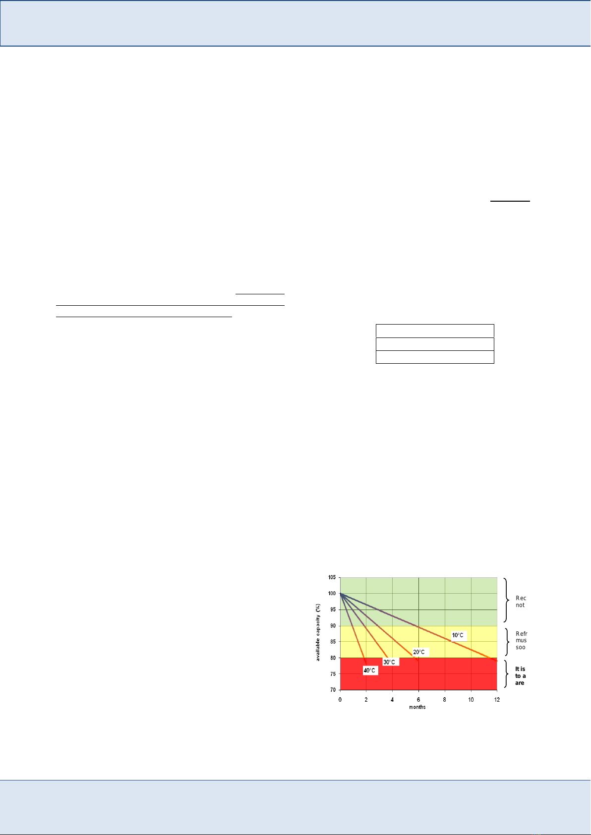
10.3.Storage time / Temperature
VRLA battery ranges have a shelf life of 6 months at a
storage temperature of 20°C.
The temperature has an impact on the self-discharge rate
of battery cells.
Higher temperatures increase the rate of self discharge
and therefore storage life is reduced.
FET AGM batteries have a self discharge rate of ≤ 2%
per month at 20°C and therefore are stored for prolonged
periods of time.
MAXIMUM storage period before refresh at the given
average storage ambient temperature is as follows :
10.4.Storage / Recharge
As during storage batteries will lose part of their capacity
due to self discharge (≤ 2% per month at 20°C), a
refreshing charge must be given :
1. when MAXIMUM STORAGE TIME is reached
OR
2. when the OCV (open circuit voltage)
approaches 2.11 V/cell
whichever occurs first.
Recharge the cells as directed in FET’S instruction table
for AGM battery type. (Usually at 2.4 volt per cell for a
period of 24 hours at 20°C).
Fig. 8 : Storage time versus temperatures
6 months at 20°C
4 months at 30°C
2 months at 40°C
It is important
to avoid this
area
Recharge is
not necessary
Refreshing charge
must be applied as
soon as possible

This document and the confidential information it contains shall be distributed, routed or made available solely with written permission of FIAMM Energy Technology.
FIAMM Energy Technology S.p.A. reserves the right to change or revise without notice any information or detail given in this publication. Pag 12 / 12
FIAMM Energy Technology S.p.A Installation & Operating Instruction -Technical Manual Edition 03/2018 Rev.7
11. VENTILATION (in accordance with EN
50272-2)
During normal operating conditions, lead acid batteries
emit low quantity of gases which can reach an explosive
mixture when hydrogen concentration is higher than
Lower Explosion Limit (LEL) threshold which is 4%vol.
The purpose of ventilating a battery location or enclosure
by natural or forced (artificial) ventilation is to maintain
the hydrogen concentration below the above stated limit.
Battery locations and enclosures are to be considered as
safe from explosions, when the concentration of
hydrogen is kept below this safe limit.
The minimum air flow rate for ventilation of a battery
location or compartment shall be in accordance with
European Standard EN 50272 calculated by the
following formula:
-3
rt xgas 10xCxIxNx0,05Q
where:
Q = ventilation air flow in m3/h
N = number of cells (each 2 Volt)
Crt= capacity C10 [Ah] at 1.80 Volt/cell at 20°C.
The current Igas [mA/Ah] producing gas as indicated in
the table of the above mentioned standard con be
assumed as:
1Igas
For batteries on float
8Igas
For batteries on boost charge
11.1.Determination of openings
The amount of ventilation air flow shall preferably be
ensured by natural ventilation, otherwise by forced
(artificial) ventilation. Battery rooms or enclosures
require an air inlet and an air outlet with a minimum free
area of opening calculated by the following formula:
Qx28A
with Q = ventilation flow rate of fresh air [ m3/h]
A = free area of opening in air inlet and outlet
[cm2]
Note: For the purpose of this calculation the air velocity is
assumed to be 0,1 m/s.
The air inlet and outlet shall be located at the best
possible location to create best conditions for exchange
of air, i.e.
openings on opposite walls,
minimum separation distance of 2 m when
openings on the same wall.
The following picture gives an indication of the correct
opening to assure a complete battery room air exchange
11.2.Forced ventilation
Where an adequate air flow Q cannot be obtained by
natural ventilation and forced ventilation is applied, the
charger shall be interlocked with the ventilation system
or an alarm shall be actuated to secure the required air
flow for the mode of charging selected. The air extracted
from the battery room shall be exhausted to the
atmosphere outside the building.
11.3.Close vicinity to the battery
In the close vicinity of the battery the dilution of
explosive gases is not always secured. Therefore a safety
distance extending through air must be observed within
which sparking or glowing devices (max. surface
temperature 300 °C) are prohibited. The dispersion of
explosive gas depends on the gas release rate and the
ventilation close to the source of release. For calculation
of the safety distance d from the source of release the
following formula applies assuming a hemispherical
dispersal of gas. The safety distance “d” is given from
the following formula:
3rt
3gas
3CxIxNx8,28d
where N depends on the number of cells per monoblock battery
(N) or vents openings per cell involved (1/N).
or vents openings per cell involved
For further information please refer to EN50272
Note: A calculation program is available on request.
This manual suits for next models
8
Table of contents
Other Fiamm Camera Accessories manuals


