FIBER SENSYS Fiber Defender FD504 User manual

PM-ENG-040 Rev H Confidential –Limited Distribution
Fiber Defender®
FD504™/ FD508™
User Manual

Page 2 Confidential –Limited Distribution
© Copyright 2019, Fiber SenSys®, Inc. all rights reserved. No part of this
publication may be reproduced or transmitted in any form or by any means,
electronic or mechanical, including photocopy, recording, or any information
storage and retrieval system, without permission in writing from Fiber SenSys, Inc.
This manual is provided by Fiber SenSys, Inc. While reasonable efforts have been
taken in the preparation of this material to ensure its accuracy, Fiber SenSys, Inc.
makes no express or implied warranties of any kind with regard to the
documentation provided herein. Fiber SenSys, Inc. reserves the right to revise this
publication and to make changes from time to time in the content hereof without
obligation of Fiber SenSys, Inc. to notify any person or organization of such
revision or changes.
FD504™and FD508™are trademarks of Fiber SenSys, Inc.
Fiber SenSys®and Fiber Defender® are registered trademarks of Fiber SenSys,
Inc.
Windows®is a registered trademark of Microsoft Corporation.
Fiber SenSys Inc.
2925 NE Aloclek Dr.
Suite 120
Hillsboro, OR 97124
USA
Tel: 1-503-692-4430
Fax: 1-503-692-4410
info@fibersensys.com
www.fibersensys.com

FD50xUser Manual Page 3
Table of contents
1. Introduction .........................................................................................................4
2. Safety Information ...............................................................................................6
3. Installing the Sensing Fiber .................................................................................9
4. Alarm Processing Unit (APU) Description..........................................................12
5. Alarm Processing Unit (APU) Setup..................................................................14
6. Maintenance......................................................................................................17

Fiber Defender FD50x User Manual 4
1.Introduction
The FD504 and FD508 are fiber optic sensors designed to detect potential intruders that are
trying to breach a perimeter. The FD504 can monitor up to four different sensing fibers (zones)
and the FD508 can monitor up to eight different sensing fibers (zones). This document will use
FD50x to mean “either FD504 or FD508.”
The FD50x detects intruders using a fiber optic sensor that is deployed on the perimeter. For
perimeters with chain-link fencing, the fiber is installed inside conduit that is tied to the fence
with stainless steel wire ties. The sensing fiber can also be deployed on decorative metal
fences, cement walls, etc. The fiber optic sensor works by measuring modulated laser radiation
that results from potential intruders who vibrate the structure to which the fiber is attached.
When the FD50x detects intruders, it sends alarm messages to a head end, and can also switch
relay contacts that can be used to manage lights, cameras, audible alarms, etc.
The optical fiber-based system has been designed to be
immune
to the effects of
Electromagnetic Interference
(
E
M
I), lightning, and Radio
Frequency
Interference (RFI). The
FD50x provides maximum effective
intrusion
detection through its inherent system flexibility and
advanced programmability.
Because the fiber optic sensors use laser light which is intrinsically inert, the FD50x system can
be installed safely at chemical plants, ammunition depots, or any location where the use of
electricity is a concern.
The FD50x is a 1U rack-mount chassis that fits into a standard 19-inch telecommunications
rack. The Alarm Processing Unit (APU) zones can have insensitive lead-in fiber for use in
remote locations. The front of the APU has indicator lights that show the status of each zone; a
steady green light indicates normal/secure operation, and red lights come on during an
attempted intrusion (alarm), or if the fiber is cut (fault). Figure 1-1 shows the front panel of the
FD508.
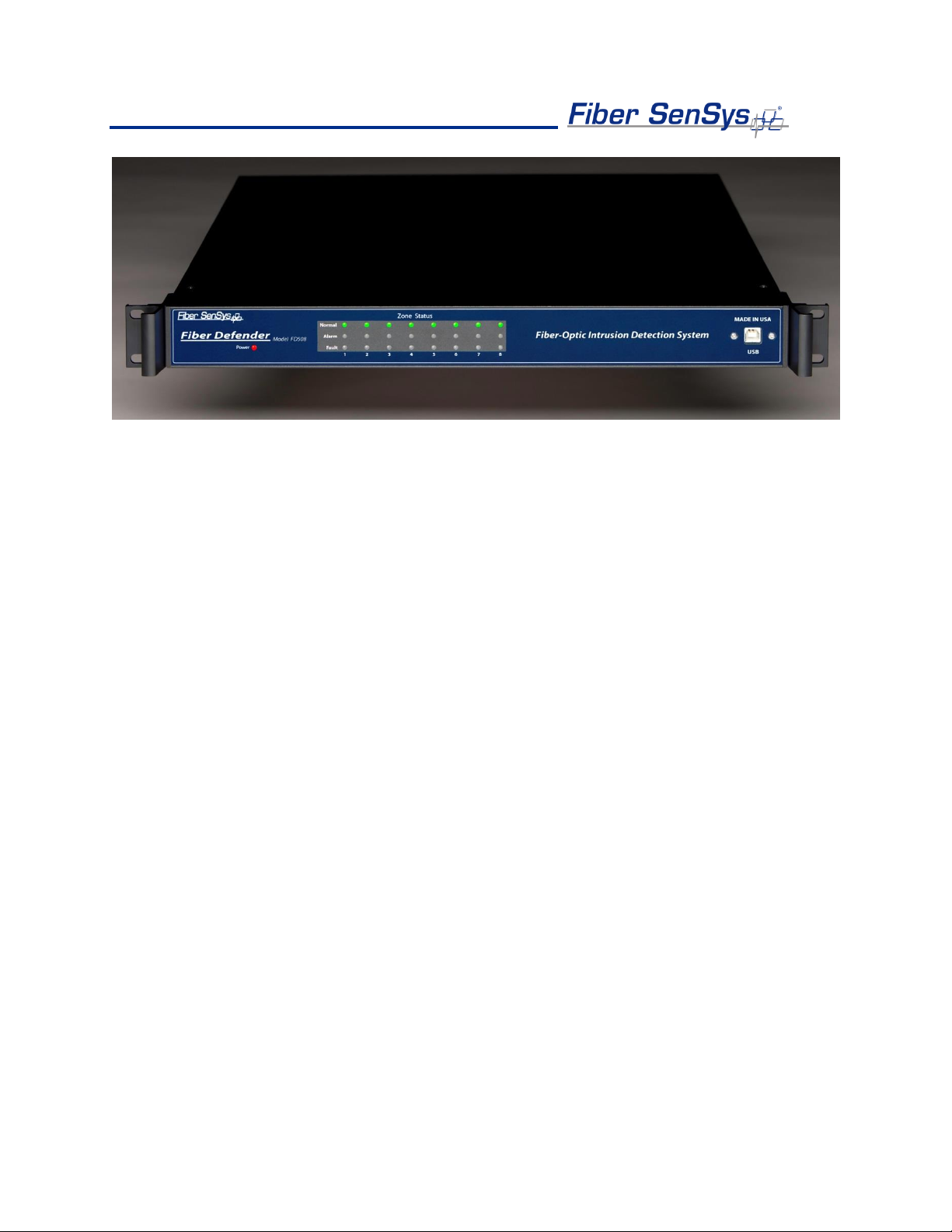
Fiber Defender FD50x User Manual 5
Figure 1-1. Front view of the FD508 APU. The FD504 is similar but supports up to four zones.

Fiber Defender FD50x User Manual 6
2.Safety Information
This section contains information to help ensure safety and the proper operation of equipment.
Please follow these instructions carefully, and keep them accessible, for future reference.
When using the FD50x, use only attachments and accessories that have been specified by FSI,
and refer all servicing to qualified personnel.
Safety Terms
The following icons may appear throughout this manual:
CAUTION: Identifies conditions or practices that could result in damage to equipment
and/or loss/contamination of data.
WARNING: Identifies conditions or practices that could result in non-fatal personal injury.
Electrical Safety
If the FD50x is damaged or malfunctions, disconnect power to the APU. Do not use the
APU if any of the following conditions exist:
•It is visibly damaged.
•It does not operate as expected.
•It has been subjected to prolonged storage under adverse conditions.
•It has been damaged during shipment.
Do not put the APU into service until qualified service personnel have verified its safety.
Covers and Panels
There are no user-serviceable parts inside the APU. To avoid personal injury, do not
remove any of the APU’s covers or panels. The product warranty is void if any factory seal
is broken. Do not operate the product unless the covers and panels are installed.

Fiber Defender FD50x User Manual 7
Inspection
The FD50x APU should be inspected for shipping damage. If any damage is found, notify
Fiber SenSys and file a claim with the carrier. Save the shipping container for possible
inspection by the carrier.
Laser Radiation
The FD50x APU is a Class 1 laser product, as defined by IEC 60825-1 and CFR 21
subchapter J. A Class 1 laser emits insufficient light to constitute a hazard. However, avoid
direct eye exposure to the output of this product or the open end of any optical-fiber cable
connected to this product.
Fiber-Handling Precautions
Warning: Optical fibers are made of glass, and the ends of broken fibers can be sharp and
may become lodged in the skin. Take appropriate handling precautions.

Fiber Defender FD50x User Manual 8
FCC Rules
Note: This equipment has been tested and complies with the limits for a Class B digital
device, pursuant to Part 15 of the FCC Rules. These limits are designed to provide
reasonable protection against harmful interference in a residential installation. This
equipment generates, uses, and can radiate radio-frequency energy. If the equipment is
not installed and used in accordance with the instructions, it may cause harmful
interference to radio communications. However, there is no guarantee that interference will
not occur in a particular installation. If this equipment does cause harmful interference to
radio or television reception, which can be determined by turning the equipment off and on,
the user is encouraged to try to correct the interference by one or more of the following
measures:
•Reorient or relocate the receiving antenna.
•Increase the separation between the equipment and receiver.
•Connect the equipment into an outlet on a circuit different from that to which the receiver
is connected.
•Consult the manufacturer, dealer, or an experienced radio/TV technician for help.

Fiber Defender FD50x User Manual 9
3.Installing the Sensing Fiber
The FD50x detects intruders by sensing small disturbances caused by vibrations induced within
a fiber optic sensor attached to the perimeter’s deployment medium. The optical sensor is a
thin strand of multimode optical fiber inside a specially designed fiber optic cable. The fiber
optic cable should be installed in such a way that, when intruders attempt to cross the
perimeter, they create slight vibrations that disturb the sensing fiber. These disturbances are
then detected by the FD50x APU, which generates the appropriate alarm(s).
Fiber Optic Sensing
When an optical fiber is exposed to vibration, the vibrations cause small asymmetric
changes in the fiber’s density. In turn, these changes in density cause measurable
changes in certain characteristics of laser radiation transmitted through the fiber. The
FD50x uses precision lasers and detectors, along with sophisticated digital signal
processing, to measure these changes in the laser radiation. The processor analyzes the
incoming signals in order to determine whether they are caused by intruders, or harmless
nuisances, such as vibrating equipment. To learn more about fiber optics and their use as
sensors, refer to the fiber optics application note titled: AN-SM-007 Fiber Optics.
Types of Installations
There are many different ways to use the FD50x system. The most common installation is
on chain-link fence. For fence-mounted applications, the fiber optic cable is installed inside
a flexible conduit, which is then secured to the fence using stainless steel wire ties. Other
applications involve installing the optical cable inside the channels of decorative metal
fence, or running the flexible conduit (with optical cable inside) along the tops of concrete
walls. For detailed information about the possible fenced perimeter installations, and site
design techniques, see the application note on site design and assessment titled: AN-ENS-
006 FD500 Series –Site Design and Assessment.
Connectors
The FD50x is a time-domain-multiplexed system that can monitor multiple fully independent
zones (sensing fibers) using a single APU. The FD504 can monitor up to four zones and
the FD508 can monitor up to eight zones. To maintain a high signal-to-noise ratio, it is
important that all optical connections in the system be made with either fusion splices or
Angled Physical Contact (APC) fiber optic connectors. Physical Contact (PC) and Ultra
Physical Contact (UPC) connectors should not be used. For more information about fiber
optic connectors, refer to the fiber optics application note: AN-SM-007 Fiber Optics.
Fiber Defender FD50x User Manual 10
The lead-in or sensing fibers plug directly into the APU and are always connected with
SC/APC connectors.
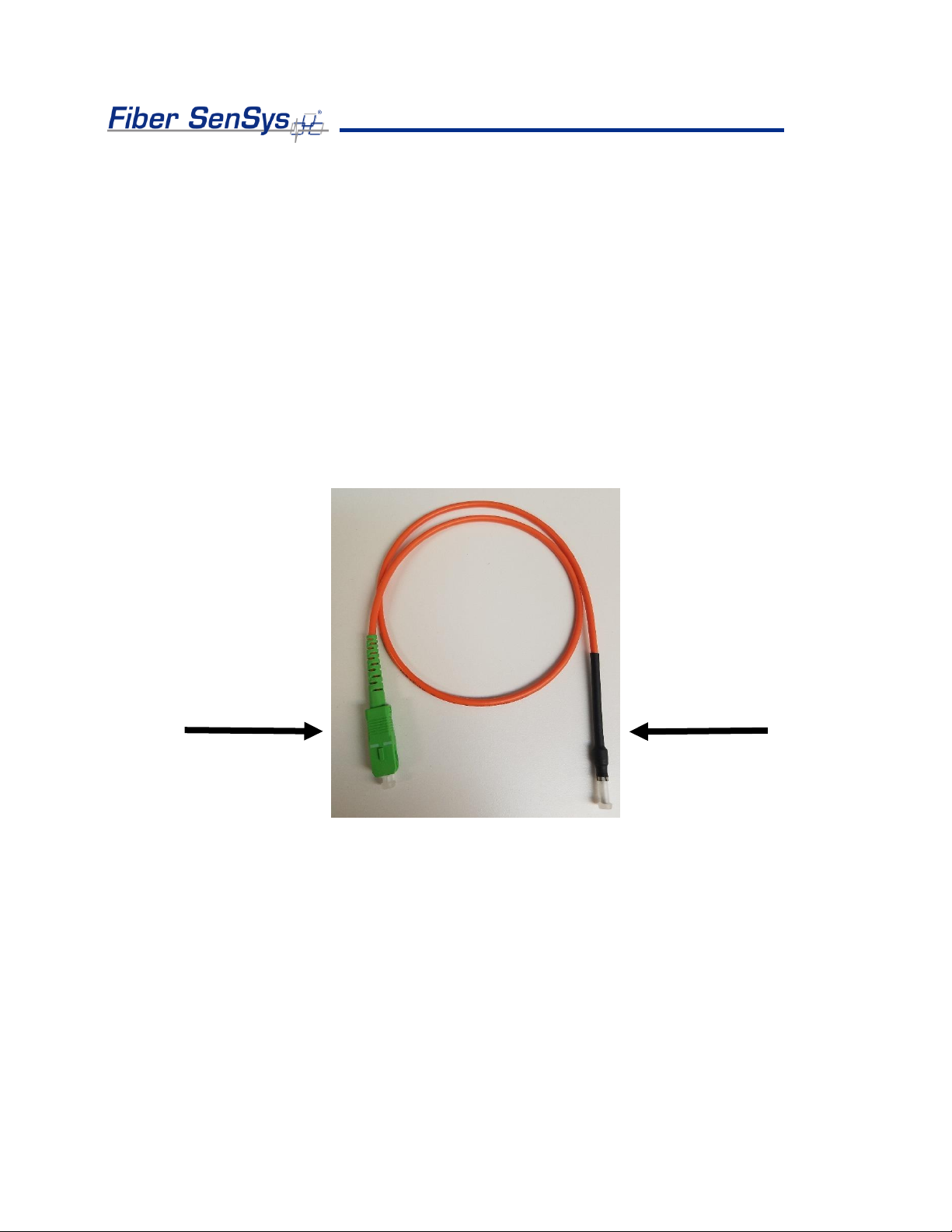
Terminations
All sensing fibers used with the FD50x are “single ended.” This means that the fiber
connects to the APU at just one end, and the other end of the sensing fiber is terminated
using a Multimode End-Of-Line (MM EOL) terminator.
The MM EOL should be installed at the end of each sensing fiber. To connect the MM EOL
to the sensor, cut the SC/APC connector off the MM EOL and fusion splice the MM EOL
directly to the multimode sensing fiber
Figure 3-1. Multimode end-of-line (MM EOL) termination module.
Cable Configuration
Typically, Fiber SenSys provides single-mode (SM) a trunk cable that carries the insensitive
lead-in fibers to all the zones. At points where a zone is desired, specialized tools can be
used to cut into the trunk cable to expose one of the insensitive lead-in fibers which is then
spliced to sensing fiber (see Figure 3-2); this technique is known as a “mid-entry.”The
splice point is fully enclosed in a breakout box which serves as a splice enclosure and is
Remove
SC/APC
Connector
Keep MM EOL
terminator end
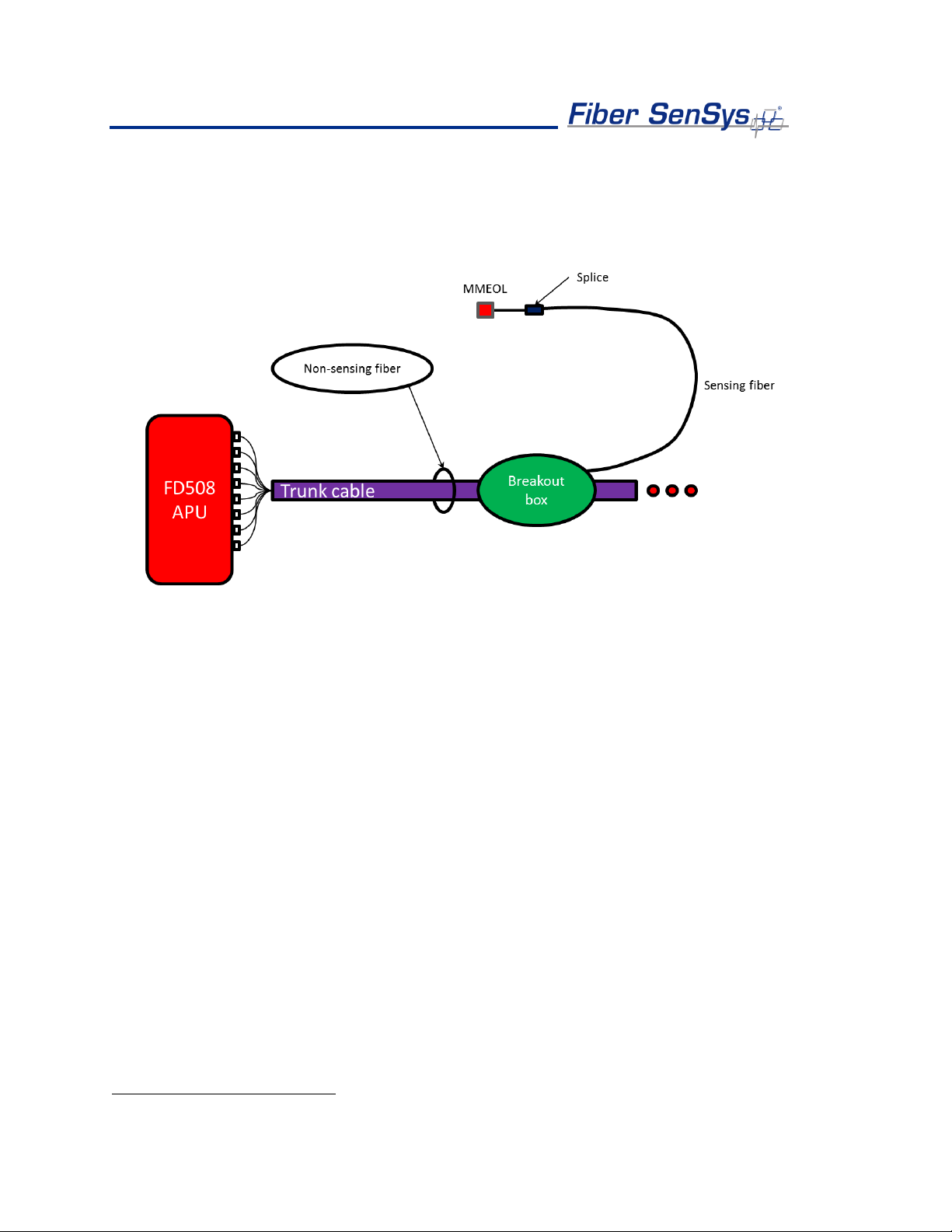
Fiber Defender FD50x User Manual 11
sold as a complete kit, including the MM EOL.
2
For more information on system topology
options, installing the trunk cable, sensors, and MM EOL, see the application note on
installing perimeter fiber optic cable: AN-SM-035 FD500 Series –Standard Installation
Instructions.
Figure 3-2. Typical system configuration. The trunk cable contains the insensitive fibers. The breakout boxes act
as splice enclosures, protecting the points where the trunk cable is accessed, when splicing the insensitive lead-
in fiber to the sensing fiber. The MM EOL is spliced onto the end of the sensing fiber. The three red dots indicate
that the trunk cable continues to other breakout boxes and other sensing fibers.
All zones must be properly installed and terminated before connecting to the APU. In
addition, it is helpful to test the optical loss of each zone. Optical loss, however, must be
tested before the MM EOL are installed on the ends of the zones (the termination units are
not transmissive). Also, each zone should be numbered, and a label with the zone number
affixed to the fiber near the connector that will plug into the APU.
2
Each breakout box can support up to two zones.
Fiber Defender FD50x User Manual 12
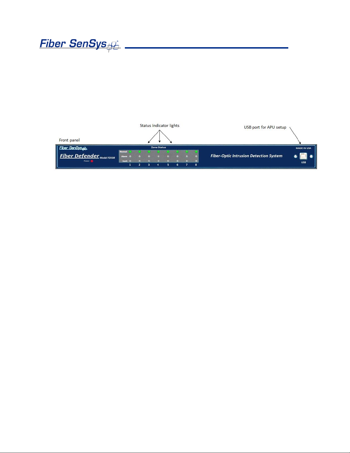
4.Alarm Processing Unit (APU) Description
The front of the APU has indicator lights that provide a quick, visual indication of the status
of each zone. Until the APU is properly configured, all the red “alarm” and “fault” lights will
be lit; after the APU is properly configured and under normal operation, the green “normal”
lights will be all lit.
Figure 4-1. Front panel of the FD508 showing the status indicator LEDs and USB port. The FD504 is similar but
supports up to four zones.
After the APU has been set up, when the APU detects an alarm on a particular zone, the
green “normal” light goes out and the red “alarm” light comes on. The red “alarm” light
illuminates while the relay is activated; both are controlled by the relay latch time setting. If
a zone is cut, the green “normal” light goes out and the red “fault” light comes on until the
zone is repaired.
In addition to the status lights, the front of the APU has a USB port. This port is used to
connect the APU to a computer to configure the APU.
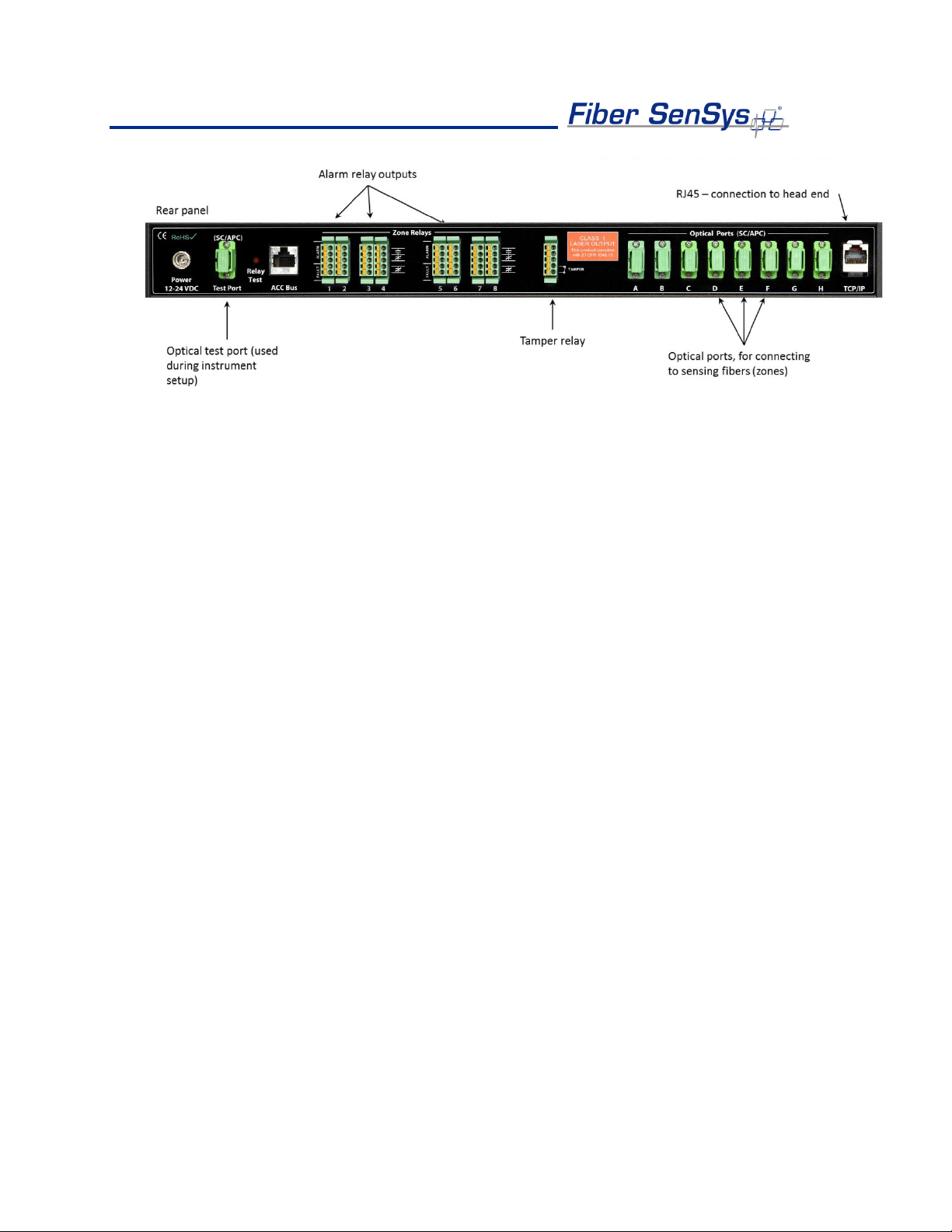
All in-service connections to the APU are made through the rear panel (see figure 4-2).
These connections include:
1. Optical ports for the fiber optic sensors that go to each zone.
2. Alarm relays for each zone.
3. Optical test port (for initial setup). Not used after configuring the APU.
4. Tamper input.
5. TCP/IP port via a RJ45 connector.
6. DC power input jack.
Fiber Defender FD50x User Manual 13
Figure 4-2. Rear panel of the FD508. The FD504 is similar but supports up to four zones.

Fiber Defender FD50x User Manual 14
5.Alarm Processing Unit (APU) Setup
Setting up the APU consists of several steps:
•Physical installation
•Attaching and configuring the optical cables
•Tuning the zones to optimize detection and reduce nuisance alarms
•Testing and validation
•Integrating the APU into monitoring systems
Physical Installation
The APU comes with a rack-mounting kit consisting of two rack-mounting handles and screws
for attaching them to the APU. Attach the handles to the APU and then mount the APU into the
rack using the rack-mounting handles.
Attaching the optical cables
The optical cables must be connected in a certain order. To do this, run the Port Assignment
Wizard from the 500 Series Software Suite. To understand the required operations, please
refer to AN-ESW-009 500 Series Port Assignment Wizard.
Note: It is important that only clean optical connectors are inserted into the APU’s test
port. Dirty connectors can degrade the performance of the APU, or even cause
irreversible damage. When laying connectors down, unconnected, make sure they have
protective caps on the ferrules. Caps should be used to protect the ferrule from damage
that might be caused by bumping the ferrule against a foreign object; unfortunately, caps
can be dirty and don’t effectively protect against microscopic contamination.
Consequently, be sure to clean all connectors prior to insertion into the alignment port,
whether they have been capped or not. For more information on the care and cleaning
of fiber-optic connectors, refer to the fiber optics application note: AN-SM-007 Fiber
Optics.
Tuning the Zones
Tuning is a process of adjusting different parameters that are used by the intruder-detection
algorithms. Tuning is necessary when installing a new system, after making changes to the
cable assembly, or after replacement of the APU. Every time the system is tuned, all affected
zones must be re-tested to verify they meet all requirements for probability of detection and
rejection of nuisance alarms.

Fiber Defender FD50x User Manual 15
Through the tuning process, the overall sensitivity of the zones (each zone can be
independently tuned), as well as parameters that help to reject nuisance alarms, can be
adjusted. To do this, run the 500 View software from the 500 Series Software Suite. To
understand the required tuning operations, please refer to AN-ENS-007 Setting the Tuning
Parameters. The software itself is described in PM-ENG-036 500 Series Software Suite User
Manual.
Testing and Validation
Probability of detection (PD) testing begins with a review of the types of threats that need to be
detected, simulating those threats, and measuring the probability with which the system detects
them. To obtain a statistically significant sample, perform each simulated threat 20 times in
each zone.
For example, to determine the PD for an intruder, simulate climb and cut intrusions, as
described in AN-ENS-007 Setting the Tuning Parameters. Perform the simulated intrusion a
minimum of 20 times, keeping track of the number of intrusions that are captured by a triggered
alarm.
Verify that the system captures enough intrusions to meet the PD requirement. If the PD is too
low, tune the system as described in section 5. Repeat this procedure for each installed zone
on the secure perimeter.
A Relay Test button is located next to the test port. The button is recessed so it cannot be
inadvertently pushed. The button can be pressed using a small screwdriver or similar tool.
Pushing the button performs a self-test, which causes the APU to temporarily activate all relays
and LEDs to their alarm or fault states. When the button is released, all relays and LEDs
resume normal communication of zone conditions.
If the tamper input on the FD50x APU is used, a Tamper Test should be performed. Test by
going to the tamper-protected enclosure, opening it, and verifying that the head end records a
tamper alarm (the tamper switch reports through the TCP/IP interface with all other system
alarms).
The Fault Test verifies that the APU correctly annunciates a fault on the correct zone upon loss
of optical power. To conduct this test, disconnect the optical fiber for zone one, and verify that
the fault light for zone one is illuminated (this light is located on the front of the APU).
Reconnect the fiber from zone one and verify that the fault light goes off. Repeat this process
for the other zones.
Note: It is important to clean all connectors prior to insertion into the optical port. Refer
to the fiber optics application note: AN-SM-007 Fiber Optics.

Fiber Defender FD50x User Manual 16
Monitoring the APU on the Network
The processes involved in integrating the APU into a security system network are described in
detail in the AN-ESW-006 APU Networking application note.

Fiber Defender FD50x User Manual 17
6.Maintenance
Maintenance consists of routine inspections and periodic testing to verify the performance of the
tamper and fault alarms, as well as the PD for simulated intrusions.
Visually inspect the APU at least every 90 days:
1. Ensure the Power LED is illuminated and all alarm and fault LED indicators are normal.
2. Check the optical connectors at the back of the APU, making sure they are not pinched
or otherwise compromised.
On a periodic basis perform the tests described in section 5:
•Tamper.
•Fault.
•Probability of detection.
•Relay function (if used).
•TCP/IP function (if used).
There are no user-serviceable parts in the APU. In case of an APU failure, corrective
maintenance involves replacing or repairing the APU with Fiber SenSys. If an APU is replaced
or repaired, or changes are made to the fiber optic sensors, repeat the steps in Section 5, Alarm
Processing Unit (APU) Setup.
To replace or reinstate the APU, follow these steps:
1. Ensure all current APU calibration parameters, as well as the system configuration
data, have been saved to a PC file using the 500 View software.
2. Disconnect power to the APU and disconnect the optical fibers.
3. If utilized, disconnect the relay terminal blocks.
4. If present, disconnect the Ethernet connection from the TCP/IP port.
5. Remove the APU and replace it with the new or repaired unit.
6. Clean all the optical connectors per the procedures described in the fiber optics
application note, AN-SM-007 Fiber Optics.
7. Insert all optical connectors, relay terminal blocks, and the Ethernet connection in
their original locations.
8. Connect power to the new APU, and load all APU calibration parameters, as well as
the system configuration data to the APU.
9. Repeat the processes described in section 5 of this manual on testing. Re-tune
zones as necessary.

Fiber Defender FD50x User Manual 18
For troubleshooting assistance, contact Fiber SenSys Technical Support Service: telephone, 1-
503-726-4455; email, support@fibersensys.com; or go to the Fiber SenSys website,
www.fibersensys.com.

Fiber Defender FD50x User Manual 19
Fiber Defender FD50x User Manual 20
Appendix A. Referenced Documents
AN-SM-007 Fiber Optics
AN-ENS-007 Setting the Tuning Parameters
AN-ESW-006 APU Networking
AN-ESW-007 Auxiliary SW Features
AN-ESW-009 Port Assignment Wizard
AN-SM-025 500 Series Optional Accessories
AN-SM-035 FD500 Series –Standard Installation Instructions
AN-ENS-006 FD500 Series –Site Design and Assessment
PM-ENG-036 500 Series Software Suite User Manual
Note: To download these documents online, please visit the Fiber SenSys website:
www.fibersensys.com
This manual suits for next models
1
Table of contents
Other FIBER SENSYS Protection Device manuals

Popular Protection Device manuals by other brands


HAVER & BOECKER
HAVER & BOECKER TYLER Ro-Tap RX-29 operating instructions

Arcteq
Arcteq AQ-M255 instruction manual

Distel
Distel Alu Plus Komfort instruction manual

Schweitzer Engineering Laboratories
Schweitzer Engineering Laboratories SEL-311L instruction manual

Dräger
Dräger CPS 7900 Instructions for use

ensto
ensto Arcteq AQ-F210 instruction manual


