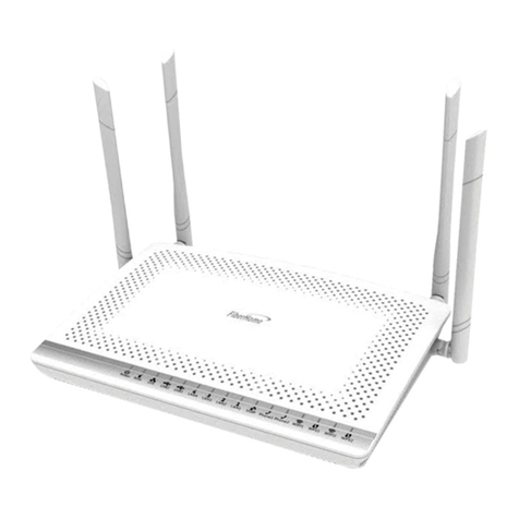
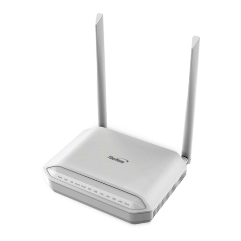
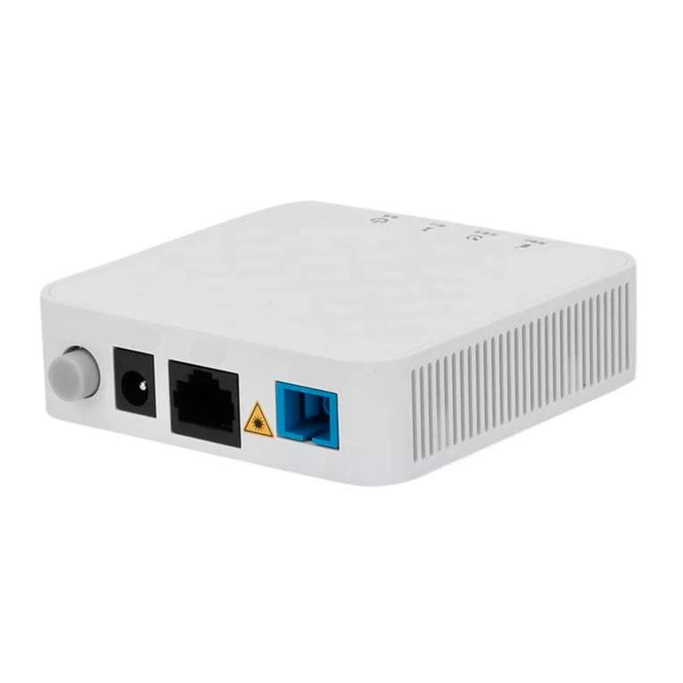
FiberHome AN5506-04-F User manual

For a correct, safe use of the equipment, please read the following carefully and rictly observe the operation
safety rules during your operations.
st
AN5506-04 F-
Code: MN000000619 Version: C
User Manual
Packing List:
AN5506-04: 1 DC or storage battery power adapter : 1 RJ 45 crystal head: 5
RJ 11 cr ystal head 3 User Manual 1 Certificate: 1. Please contact your supplier if
anything is missing.
●● ●-
●- :● :●
Thank you for choosing FiberHome products.
Operation Safety Rules
Avoid moisture, dampness and water damage. Equipment exposed to water cannot work
normally and can be extremely hazardous due to shorting.
Do not lay this equipment on an unsteady base.
Interfaces and Connections
Equipment Installation
The AN5506-04-F can be horizontally or vertically placed on a desk, or hung against the wall.
GPON
Optical Network Unit
Technical Specification
Description
Type Item
Mechanical
parameters
Power supply
parameter
Power consumption
parameter
Dimension
Weight
DC
AN5506-04-F
Operating temperature
Storage temperature
Environmental humidity
45
/.
-30℃ 60℃
10% 90%
mm×235mm×174mm H W D)
390g approximately
DC 12V 1 5A
12W
-5℃ to
to
to , non-condensing
(
45℃
Indicator LED Description
Power status LED (green)
ON: The equipment is
powered on
OFF: The equipment is not
powered on
VOIP status LED (green)
ON: The equipment registers to the
softswitch system successfully
OFF: The equipment does not
register to the softswitch system
Phone port LED (green)
ON: The equipment registers to the
softswitch platform successfully
Blinking: The port is transmitting service flow
ON: The equipment fails to register to the
softswitch platform
Registration status LED (green)
ON:TheONUisactivated
OFF: The ONU is not activated
Wireless signal status LED (green)
ON: The wireless interface is enabled
Blinking: Service flow transmission exists
OFF: The wireless interface is disabled
Optical signal status LED (red)
Blinking: The equipment receives no
optical signal.
OFF: The equipment receives optical
signals.
Ethernet interface status LED (Green)
ON:Theinterfaceisconnectedtotheuserterminal
without data transmission
Blinking: The interface is transmitting
and receiving data
OFF: The interface is not connected
to the user terminal
Horizontally placed Verticall placed
12 13 14 15
12 Button for setting WI FI
safety protection
13 Reset key
14 Wireless switch
15 USB interface
.-
.
.
.
Highopticalpowercancausebodilyharm,especiallytoeyes.Neverlookdirectlyintothe
endoftheopticaltransmitterfiberjumperortheendofitsactiveconnector.
Exercise care if you must bend fibers. If bends are necessary, the fiber bending radius should
neverbelessthan38mm.
Power socket overload, brokencables or broken plugs may cause electric shock or fire.
Regular check-ups on powersupply wires and cables are essential. If any appears damaged,
replace at once.
Use the power supply adapter provided in the package only.Using other adapters may cause
equipment damage or operation failures.
Install the equipment in a well ventilated environment without high temperatures or direct
sunlight to protect the equipment and its components from overheating, which can result in
damage.
Uses GPON uplink that is compliant with ITU-T G.984 series of standards;
Supports Ethernet interface rate, working mode, MDI / MDIX auto-negotiation mode;
Supports packet filtering and DoS attack protection;
Provides performance statistics on all Ethernet lines;
Supports reporting the physical position information of Ethernet interfaces through DHCP Option82;
Supports the PPPoE+ function for obtaining user IP address and accurate user identification;
Supports various voice protocols including H.248 and SIP;
SupportsIGMPsnoopingprotocol;
Supports the L2 / L3 wire speed forwarding;
Supports the AES-128 algorithm for data encryption of downlink data;
Supports global configuration of queue priority and flexible mapping of 802.1p value of packets. Supports
the PQ queue scheduling mode. You can configurethe weight of scheduling queue to ensure the QoS of the
services with high QoS requirement such as voice and video under multiple service conditions;
Supports wireless access mode, compliant with the 802.11 b/g/n standard;
Supports the following authentication modes: open, shared, wpapsk, wpa2psk, wpapskwpa2psk. Supports
the following encryption modes: none, wep, tkip, aes, and tkipaes.
The AN5506-04-F is an FTTH GPON optical network unit. It provides communication and entertainment service in multiple modes such as
data, voice, and video, to meet integrated access requirement of families or small enterprises. The AN5506-04-Fsupports these functions:
Product Introduction
Wall Mounting
12
USB LED
USB
USB
USB
(green)
ON: The is connected without data transmission
Blinking: The is transmitting and receiving data
OFF: The is not connected
6. LAN switch
LED switch
USB
7.
8.
9.
10.
11.
Button for setting WI FI
safety protection
Reset key
Wireless switch
interface
-
78911
610
AN5506 04 F2G Side Panel--
AN5506-04-F2G
AN5506-04-F3
4GEportsand2phone
ports
1GEport,3FEports
and 2 phone ports
External antenna
Built-in antenna
Environmental
parameter
2. Drill two holes and install
expansion bolts
3. Install screws and hang the
equipment on them
12
345
1. Network interface Voice interface Optical interface
Power switch Power interface
2. 3.
4. 5.
AN5506 04 F3 Side Panel--
Optical
interface
PC
Best antenna position
Laptop
Smart
phone
Power
adapter
Phone
●●●●●●●●●●● ● ●
1. Mark the installation
position

Logging into Web Configuration GUI FAQs
.
Step 1 Network Authentication Settings OLT Authentication
Step 2
Step 5 Apply
Select → → in the navigation bar.
In the screen that is opened, modify related parameters of ONU authentication.
ConfigureLogicSNandpasswordofSNauthentication
Click to save the settings.
Step 3 Apply
Step 4
Click to save the settings.
Configure the password of password authentication.
Configuring ONU Authorization
Step 1
Step 2
Set the IP address and subnet mask of the computer.
Select the Obtain an IP address automatically mode.
SetthestaticIP:TheIPaddressshouldbeinthesamenetworksegmentasthe
management IP address of the AN5506-04-F (recommended).
IP address: 192.168.1.X (X is a decimal integer between 2 and 253)
Subnet mask: 255.255.255.0
Enter http://192.168.1.1 in the address bar of the browser and press Enter. The user login dialog box
appears.
Step 3 Enter the user name and password in the login dialog box. After being verified, you can
access the Web configuration GUI.
Configuring Internet Access Service
Step 1 Network BroadBand Settings
Step 2 PPPoE
Step 3
Select in the navigation bar and click in the link bar to
open the configuration GUI for the Internet access service.
Select (recommended) for the WAN connection type.
Enter parameters of the PPPoE mode.
“”,。4
Configuring WIFI Wireless Access Service
Step 1 Network Wlan Settings
Step 2 RADIO ON
Step Network Mode
Step 4 AutoSelect channel1 channel 14 Frequency (Channel)
3
.
Select in the navigation bar and click in the link bar to open
the configuration GUI for the wireless access service.
Select to enable the WLAN service.
Select b/g/n for the .
Select or to for the in the
drop-down list
802.11
!
●●● ●
!
Note:
Parameters of the PPPOE mode includes:
User Name: Enter the user name provided by the ISP.
Password: Enter the password provided by the ISP.
Verify Password: Enter the password for a second time to verify whether the
passwords entered at the two times are the same.
Operation Mode: Select either the Keep Alive mode or the Manual mode in the
pulldown menu. Configuring LAN Service
Step Network LAN Settings LAN Settings
Step 2
Step 3
1
4 “ ,。
Select → → in the navigation bar. In the screen
that is opened, you can configure the LAN parameter.
Enter the LAN-side IP address 192.168.1.1 of the AN5506-04-F.
Enter the LAN-side subnet mask 255.255.255.0 of the AN5506-04-F.
”
Step 5 Network DHCP Serve DHCP Service
Step 6 Sever
Select → r → in the navigation bar. In the screen
that is opened, you can configure the DHCP server parameters.
Select for the DHCP type and configure DHCP server parameters.
:
Note:
Parameters to be configured of the DHCP server include
Start IP Address: Enter the starting value 192.168.1.2 of the IP addresses
automatically allocated by the DHCP server.
End IP Address: Enter the ending value 192.168.1.253 of the IP addresses
automatically allocated by the DHCP server.
Primary DNS Server: Enter the IP address 192.168.1.1 of the primary DNS
server of the DHCP.
Default Gateway: Enter the default gateway IP address 192.168.1.1 of the DHCP.
Subnet Mask: Enter the subnet mask 255.255.255.0 designated by the DHCP server.
!
●●●●●
Step Apply6Click to save the configured data. Step 7 ApplyClick to save the settings.
FAQ1: All indicator LEDs are extinguished after power-on.
FAQ2: The equipment fails to work.
FAQ3: LOS blinks
FAQ4 The LAN indicator LED is extinguished.
FAQ5:
FAQ6: Web p ag e
1.
2.
3.
1.
2.
1.
2.
3.
4.
5.
2.
3.
2.
1.
2.
Check whether the power cable is correctly connected;
Check whether the power supply and the power adapter are normal;
If the equipment works abnormally, check whether the power is connected normally or
the voltage is not within specifications;
If the equipment is overheated, check the ventilation. Make sure the equipment is not
exposed to direct sunshine or is near the heat source.
The indicator LED .
Check the received optical power levels with an optical power meter. Excessively low
receive optical power may indicate the fiber is faulty;
Check whether the optical fiber is connected normally to the appropriate interface;
Check whether the Rx optical power of the ONU crosses the normal optical power range
(overlow or overhigh);
Check whether the ONT module is aged or damaged;
Check whether the equipment at the central office end is operating normally.
Check if the network cable is damaged or incorrectly connected;
Check if the wiring color-coding scheme of the network cable is incorrect. If incorrect,
replace the original network cable with a standard CAT-5 twisted-pair network cable.
Check if the network cable crosses the allowed range of 100 meters.
The WIFI indicator LED is extinguished.
Checkifthewirelessterminalisconnected;
Check if the wireless function is disabled.
Logging into the failed.
Check the network card configuration, browser version of the user's computer;
Check whether the IP address of the user's computer is correctly configured.
Check whether the power switch on the equipment's rear panel is in the ON position.
:
1.
1.
●●
!
:
...
...
Note
IP Address: 192 168 1 1
Subnet mask: 255 255 255 0
The factory default management IP address and the subnet mask of the AN5506-04-F are:
●●
!
Note:
The factory default username and password of the AN5506-04-F are:
Username: admin
Password: admin
●●
◆◆
Note: The SN authentication and password authentication can be separately
configured and applied.
!
Note: If the connection fails after a channel is selected, another AP equipment
nearby is watching this channel. Please retry the connection after changing to
another channel.
Other manuals for AN5506-04-F
1
Table of contents
Other FiberHome Network Router manuals
