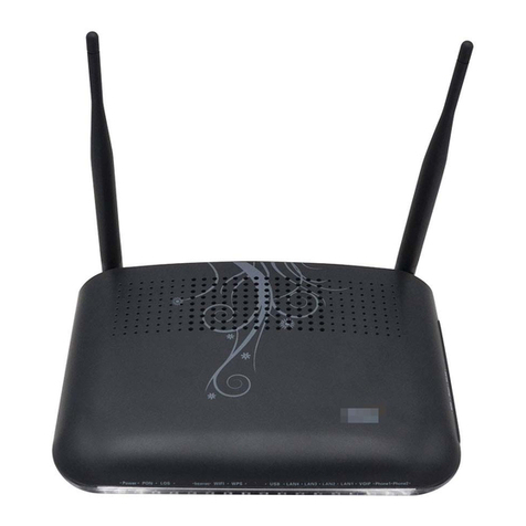
FiberHome HG110 User manual

1
ADSL ROUTER
USER MANUAL
Product name: ADSL ROUTER
Product model: HG110
Version: V111
Date: 201406

2
NOTICE
This document contains proprietary information protected by copyright, and this
Manual and all the accompanying hardware, software, and documentation are
copyrighted. All rights are reserved. No part of this document may be photocopied or
reproduced by mechanical, electronic, or other means in any form.
The manufacturer does not warrant that the hardware will work properly in all
environments and applications, and makes no warranty or representation, either
expressed or implied, with respect to the quality, performance, merchantability, or
fitness for a particular purpose of the software or documentation. The manufacturer
reserves the right to make changes to the hardware, software, and documentation
without obligation to notify any person or organization of the revision or change.
All brand and product names are the trademarks of their respective owners.
© Copyright 2014
All rights reserved.

3
Content
1.Overview.................................................................................................................................1
1.1.Features...................................................................................................................1
1.2.Packet Contents .....................................................................................................4
1.3.System Requirements ...........................................................................................5
1.4.Factory Defaults......................................................................................................5
1.5.Warnings and Cautions .........................................................................................5
2.Hardware Description .........................................................................................................6
3.Hardware Installation ..........................................................................................................7
4.PC Configuration Guide .....................................................................................................8
4.1.Local PC Configuration in Windows 95, 98, ME, XP,7......................................8
4.2.Local PC Configuration in Windows 2000..........................................................8
5.Web-based Management Guide........................................................................................9
5.1.LAN setting page....................................................................................................9
5.2.Quick start................................................................................................................9
5.3.Internet Access Configuration.............................................................................12
5.4.3G Setting..............................................................................................................15
5.5.LAN setting............................................................................................................15
5.6.Wireless setting ....................................................................................................17
5.7.Advanced Setup ...................................................................................................20
5.8.Access management ...........................................................................................23
6.Maintenance guide.............................................................................................................26
6.1.Modify login password configuration interface.................................................26
6.2.Time Zone..............................................................................................................26
6.3.Firmware Update..................................................................................................26
6.4.Factory Default Settings......................................................................................27
7.Status ....................................................................................................................................27
8.Safety Precautions.............................................................................................................28
9.Appendix: Frequent Asked Questions .........................................................................29

Wireless ADSL Router User Manual
1
1. Overview
The HG110 series is a high-performance wireless ADSL Home gate. It combining an
DSL modem, an 802.11n wireless router, and 4-port switch in one unit, bringing
high-speed wireless Internet connection to a home or office provides. The maximum
transmission speed will up to 24Mbps (uplink) and 2.5Mbps (downlink).
It can supply following service ports :
1 - 4 Fixed 10/100 BASE-TX port
2*2 WiFi
1.1. Features
1.1.1. ADSL
Full-rate ANSI T1.413 issue 2
ITU-T G.992.1 (G.dmt), supporting AnnexA or B
ITU -TG.992.2 (G.lite), supportingAnnex A or B
ITU-T G.992.3 (G. dmt.bis), supporting Annex A or B, Annex L and
Annex M
ITU-T G.992.4 (G.lite.bis), supporting Annex A or B
ITU-T G.992.5 (ADSL2+), supporting Annex A or B, Annex L and
Annex M
ITU-T G.994.1 (G.hs)
Operating distance up to 5km
Data Transmission Rate
Upstream: Up to 3.5Mbps (With Annex M enabled)
Downstream: Up to 24 Mbps.
Rate Adaptive at 32 Kbps steps
Interoperable with all major DSLAM equipments
1.1.2. ATM and PPP
RFC2684 Bridge and Routed LLC& VC
RFC1661/RFC2364 PPP over ATM ALL5
RFC2516 PPP over Ethernet

Wireless ADSL Router User Manual
2
RFC5072 PPP IPv6
RFC2225/RFC1577 Classical IP over ATM
RFC1483 Transparent Bridge
RFC 1483/2684 Bridged Ethernet
RFC 826 RARP
RFC 2684 MER
ATM Forum UNI 3.1/4.0, ATM Adaptation Layer Type 5-AAL5
VPI Range (0-255) and VCI range (32-65535)
UBR, CBR, VBR-rt, VBR-nrt
F4/F5 OAM Loopback
AIS and RDI OAM cells
Supports 8 PVCs
1.1.3. Wireless
Complies with IEEE 802.11n IEEE 802.11g and IEEE 802.11b
11n: Up to 300Mbps (dynamic, 2T2R MIMO)
Provides WPA/WPA2 and WPA-PSK/WPA2-PSK authentication and
TKIP/AES encryption security
Multi SSID
WMM
Access Control List
Provides 64/128-bit WEP encryption security
Wireless operating range: Indoor up to 100m, Outdoor up to 300m
Wireless transmit power: 20dBm
1024/256/64/16QAM/QPSK/BPSK self-adaption
1.1.4. Network Protocols
Static IP, Dynamic RIPv1, RIPv2 support
MTU Adjustment
Network Address Translation (NAT)
PVC Port Mapping (Ethernet ports)
Port Forwarding

Wireless ADSL Router User Manual
3
NATApplication Level Gateway for popular applications
DHCP Server/Relay/client
RFC 3315/RFC3633 DHCP IPv6
DNS Relay Agent
DMZ support
DDNS support
SNMP v1, v2 support
UPnP (Universal Plug and Play)
TR069 CWMP
IPV4/IPV6
PPPAuto Reconnect and configurable timeouts
PPPAuto Reconnect on WANAccess/PPP on Demand
IGMP v.1/v.2/v.3 snooping
IGMP Multicast Support
ALG for SIP and H.323
VLSM
RFC 4892 SLAAC
RFC 792/ RFC4443 ICMP
RFC 3810/RFC 4604 MLD
1.1.5. Management Support
Web Based GUI
Upgrade or update via FTP/HTTP
Command Line Interface via serial interface or Telnet
Diagnostic Test
Firmware upgrade-able for future feature enhancement
Supports Remote Access Control
1.1.6. Security Support
PAP/CHAPAuthentication for PPP mode
NAT for basic Firewall support
State Packet Inspection (SPI) for Firewall with denial-of-service

Wireless ADSL Router User Manual
4
(DoS) protection
ALG (Application-level gateway) for NAT/PAT support
2 Level (User/Admin) Password Authentication to Router
IP Filtering
MAC Filtering
Parental control
1.1.7. VPN Pass-Through
IPSec/PPTP/L2TP Pass-through
1.1.8. QoS
Classification Rules
Priority Queuing
802.1p
1.1.9. Operating System Support
WINDOW 98/98SE/ME/2000/XP/VISTA/7
Macintosh
LINUX
1.1.10. Environmental
Running temperature 0ºC~60ºC
Storage temperature -20ºC~70ºC
Operating humidity 10%~90% ,on-condensing
Storage humidity 5%~95% ,Non-condensing
1.1.11. EMC and safety
EMC EN55022 B(CISPR 22B)
Environment-protection standard RoHS
1.1.12. Electrical specifications
Power Supply DC12V(attached DC12V-AC220V convertor)
Power Consumption(full configured ) 10W
1.2. Packet Contents
The packet contents are as the following:
ADSL ROUTER x 1
External Splitter x 1 (With microfilters integrated)

Wireless ADSL Router User Manual
5
Power Adapter x 1
Telephone Line x 2 (1m & 2m)
Ethernet Cable x 1
Base x1
CD x1
(User Manual. Quick Installation Guide. Installation software)
1.3. System Requirements
Before using this ROUTER, verify that you meet the following requirements:
Subscription for ADSL service. Your ADSL service provider should
provide you with at least one valid IP address (static assignment or
dynamic assignment via dial-up connection).
One or more computers, each contains an Ethernet 10/100M
Base-T network interface card (NIC).
A hub or switch, if you are connecting the device to more than one
computer.
For system configuration using the supplied web-based program: A
web browser such as Internet Explorer v5.0 or later, or Netscape
v4.7 or later.
1.4. Factory Defaults
The device is configured with the following factory defaults:
IPAddress: 192.168.1.1
User Name: admin
Password: 1234
Subnet Mask: 255.255.255.0
SSID: Ralink_AP
Encapsulation: RFC 2516 LLC
VPI/VCI: According to local information
1.5. Warnings and Cautions

Wireless ADSL Router User Manual
6
Never install telephone wiring during storm. Avoid using a telephone
during an electrical storm. There might be a risk of electric shock
from lightening.
Do not install telephone jacks in wet locations and never use the
product near water.
To prevent dangerous overloading of the power circuit, be careful
about the designed maximum power load ratings. Not to follow the
rating guideline could result in a dangerous situation.
Please note that telephone line on modem must adopt the primary
line that directly outputs from junction box. Do not connect Router to
extension phone. In addition, if your house developer divides a
telephone line to multi sockets inside the wall of house, please only
use the telephone that has connected with the splitter of ADSL
Router when you access the Internet. Under the above condition, if
you also install telephone with anti-cheat-dial device, please pull out
this kind of telephone, otherwise ADSL Router may occur frequently
off-line.
2. Hardware Description
Indicators Description
LED Color Function
Power Green On: Power on
Off: No power
LAN1,2,3,4 Green On: LAN link established and active via LAN port
Blinking: Data activity occurs Off: No LAN link via LAN port
WLAN Green
On: The wireless module is ready and idle
Blinking: Data transmitting or receiving over WLAN
Off: The wireless function is off

Wireless ADSL Router User Manual
7
DSL Green
On: ADSL link established and active Quick blinking: ADSL is trying
to establish a connection
Slow blinking: No ADSL link
Internet Green On: IP connected
Blinking: IP traffic is passing thru this device Off: No ADSL
connection is present
WPS Green
On:The router has passed the WPS function
Off:without the WPS function.or dysfunction of the WPS
Blinking:router is connected via wireless client
Rear panel
Port Function
ADSL Connect the device to an ADSL telephone jack or splitter using a RJ-11
telephone cable
LAN1,2,3,4 Connect the device to your PC's Ethernet port, or to the uplink port on your
hub/switch, using a RJ-45 cable
DC12V Connect to the supplied power adapter
Key Description
WIFI:switchofwireless
WPS:switchofWirelessonthecode
RESET:switch of reboot the ONU, press and hold 10s will reset to factory set
3. Hardware Installation
This chapter shows you how to connect Router. Meanwhile, it introduces the appropriate
environment for the Router and installation instructions.

Wireless ADSL Router User Manual
8
1. Using a telephone line to connect the ADSL port of ROUTER to the MODEM
port of the splitter, and using a other telephone line connect your telephone to the
PHONE port of the splitter, then connect the wall phone jack to the LINE port of
the splitter.
The splitter comes with three connectors as below:
LINE: Connects to a wall phone jack (RJ-11 jack)
MODEM: Connects to the DSL jack of ROUTER
PHONE: Connects to a telephone set
2. Using an Ethernet Cable to connect the LAN port of the ROUTER to your LAN
or a PC with network card installed.
3. Connect the power cable to the PWR connector on ROUTER, then plug in the
power adapter to the AC power outlet, and then press the on-off button.
4. PC Configuration Guide
4.1. Local PC Configuration in Windows 95, 98, ME, XP,7,8
1. In the Windows task bar, click the “Start” button, point to “Settings”, and then
click “Control Panel”.
2. Double-click the “Network” icon.
3. On the “Configuration” tab, select the TCP/IP network associated with your
network card and then click “Properties”.
4. In the “TCP/IP Properties” dialog box, click the “IP Address” tab. Set the IP
address as 192.168.1.x (x can be a decimal number from 2 to 254.) like
192.168.1.2, and the subnet mask as 255.255.255.0.
5. On the “Gateway” tab, set a new gateway as 192.168.1.1, and then click
“Add”.
6. Configure the “DNS” tab if necessary. For information on the IP address of
the DNS server, please consult with your ISP.
7. Click “OK” twice to confirm and save your changes.
8. You will be prompted to restart Windows. Click “Yes”.
4.2. Local PC Configuration in Windows 2000
1. In the Windows task bar, click the “Start” button, point to “Settings”, and then
click “Control Panel”.
2. Double-click the “Network and Dial-up Connections” icon.
3. In the “Network and Dial-up Connections” window, right-click the “Local Area
Connection” icon, and then select “Properties”.
4. Highlight “Internet Protocol (TCP/IP)”, and then click “Properties”.
5. In the “Internet Protocol (TCP/IP) Properties” dialog box, set the IP address

Wireless ADSL Router User Manual
9
as 192.168.1.x (x can be a decimal number from 2 to 254.), and the subnet
mask as 255.255.255.0 and the default gateway as 192.168.1.1. Then click
“OK”.
6. Configure the “DNS” tab if necessary. For information on the IP address of
the DNS server, please consult with your ISP.
7. Click “OK” twice to confirm and save your changes.
5. Web-based Management Guide
In order to use the web-based management software it will be necessary to use a
computer that occupies the same subnet as the Router. The simplest way to do
this for many users will be to use DHCP server that is enabled by default on the
Router. This is available for Windows 95, 98, XP, Vista, Windows 7, Windows 8,
Linux, and Macintosh.
5.1. LAN setting page
Launch a web browser, such as Internet Explorer, and then use http://192.168.1.1
to log on to the setting pages.
Enter username ‘admin’ and password ‘1234’,click OK.
5.2. Quick start
From home page, you can find Quick Startoption on the above router
configuration page.

Wireless ADSL Router User Manual
10
1.click RUN WIZARD and you’ll see the following screen
2.Click NEXT to change the admin account password by entering in a new password.
3.Click the NEXT to select the appropriate time

Wireless ADSL Router User Manual
11
4.Click NEXT to Select the Internet connection type to connect to your ISP, just choose
PPPoE for example here
5.Click NEXT to enter the PPPoE/PPPoA information provided to you by your ISP
6.Click NEXT to save the username and password

Wireless ADSL Router User Manual
12
7.Click NEXT to save the current setting.
5.3. Internet Access Configuration
From home page, you can find Interface setup option on the above router
configuration page.Click Internet and you’ll see the following screen.

Wireless ADSL Router User Manual
13
5.3.1. ATM VC
ATM settings are used to connect to your ISP. Your ISP provides VPI, VCI settings to you.
In this Device, you can totally setup 8 VCs on different encapsulations, if you apply 8
different virtual circuits from your ISP. You need to activate the VC to take effect. For PVCs
management, you can use ATM QoS to setup each PVC traffic line's priority.
Virtual Circuit Select the VC number you want to setup.
VPI Virtual Path Identifier.
VCI Vitrual Channel Identifier.
ATM QoS Select the Quality of Service types for this Virtual Circuit. The ATM QoS types
include CBR (Constant Bit Rate), VBR (Variable Bit Rate) and UBR (Unspecified Bit Rate).
These QoS types are all controlled by the parameters specified below, including PCR, SCR
and MBS.
PCR Peak Cell Rate.
SCR Sustained Cell Rate.
MBS Maximum Burst Size.
5.3.2. Encapsulation
Dynamic IP Select this option if your ISP provides you an IP address automatically.
This option is typically used for Cable services. Please enter the Dynamic IP
information accordingly.
Static IP Select this option to set static IP information. You will need to enter in the
Connection type, IP address, subnet mask, and gateway address, provided to you by
your ISP. Each IP address entered in the fields must be in the appropriate IP form,
which is four IP octets separated by a dot (x.x.x.x). The Router will not accept the IP

Wireless ADSL Router User Manual
14
address if it is not in this format.
PPPoA/PPPoE Select this option if your ISP requires you to use a PPPoE connection.
This option is typically used for DSL services. Select Dynamic PPPoE to obtain an IP
address automatically for your PPPoE connection. Select Static PPPoE to use a static
IP address for your PPPoE connection. Please enter the information accordingly.
Bridge Mode The modem can be configured to act as a bridging device between your
LAN and your ISP. Bridges are devices that enable two or more networks to
communicate as if they are two segments of the same physical LAN. Please set the
Connection type
5.3.3. PPPoE/PPPoA
Select this option if your ISP requires you to use a PPPoE connection. This option is
typically used for DSL services. Select Dynamic PPPoE to obtain an IP address
automatically for your PPPoE connection. Select Static PPPoE to use a static IP
address for your PPPoE connection. Please enter the information accordingly.
Username Enter your username for your PPPoE/PPPoA connection.
Password Enter your password for your PPPoE/PPPoA connection
Encapsulation For both PPPoE/PPPoA connection, you need to specify the type of
Multiplexing, either LLC or VC Mux.
Connection Setting For PPPoE/PPPoA connection, you can select Always
on or Connect on-demand. Connect on demand is dependent on the traffic. If there
is no traffic (or Idle) for a pre-specified period of time), the connect will tear down
automatically. And once there is traffic send or receive, the connection will be
automatically on. Static/Dynamic IP Address For PPPoE/PPPoA connection, you
need to specify the public IP address for this ADSL Router. The IP address can be
either dynamically (via DHCP) or given IP address provide by your ISP. For Static IP,
you need to specify the IP address, Subnet Mask and Gateway IP address.
5.3.4. NAT
NAT Select this option to Activate/Deactivated the NAT (Network Address Translation)
function for this VC. The NAT function can be activated or deactivated per PVC basis.
5.3.5. Default Route
Default Route if enable this function, the current PVC will be the default gateway to
internet from this device.
5.3.6. Dynamic Route
RIP (Routing Information protocol) Select this option to specify the RIP version,
including RIP-1, RIP-2M and RIP-2B. RIP-2M and RIP-2B are both sent in RIP-2
format; the difference is that RIP-2M using Multicast and RIP-2 using Broadcast
format.
RIP Direction Select this option to specify the RIP direction. None is for disabling the
RIP function. Both means the ADSL Router will periodically send routing information
and accept routing information then incorporate into routing table. IN only means the
ADLS router will only accept but will not send RIP packet. OUT only means the ADLS
router will only send but will not accept RIP packet.
5.3.7. Multicast
IGMP (Internet Group Multicast Protocol) is a session-layer protocol used to establish

Wireless ADSL Router User Manual
15
membership in a multicast group. The ADSL ATU-R supports both IGMP version 1
(IGMP-v1) and IGMP-v2. Select None to disable it. This function is most for IPTV.
Note:
In the Web configuration page, when you change the parameters, it is not working
immediately. It’s only temporary. If you want to save the settings of this parameters
permanently, click Save at the bottom of the Web page. If you change one parameter,
other parameters will not change.
5.4. 3G Setting
From home page, you can find 3G option on the above router configuration page. Clip
3G. In this page you can set 3G work model and status.
5.4.1. 3G Status
3G status can activate to use 3G USB data link card to access to Internet.
3G Backup allows 3G USB data link card as a backup of DSL.
5.4.2. ISP Setting
Set ISP configuration of 3G USB data link card.
5.4.3. Connection Setting
Set connection parameters.
Support 3G USB dongle type:
WCDMA:Huawei :EC122 E261,E1750,E173,E303,E367,
Alcatel:X500, Prolink: PHS101, PHS100, PHS300; TW: WU260, ZTE MF190;,
CDMA2000:T-linking TWA-137A+ and more…
5.5. LAN setting
From home page, you can find Interface setup option on the above router configuration page.
Click LAN. In this page, you can use DHCP (Dynamic Host Configuration Protocol) to control

Wireless ADSL Router User Manual
16
the assignment of IP addresses on your local network (LAN only).
5.5.1. DHCP Server
DHCP stands for Dynamic Host Control Protocol. The DHCP Server gives out IP
addresses when a device is booting up and request an IP address to be logged on to
the network. That device must be set as a DHCP client to obtain the IP address
automatically. By default, the DHCP Server is enabled. The DHCP address pool

Wireless ADSL Router User Manual
17
contains the range of the IP address that will automatically be assigned to the clients
on the network.
Starting IP Address The starting IP address for the DHCP server's IP assignment.
IP Pool Count The max user pool size.
Lease Time The length of time for the IP lease.
5.5.2. DHCP Relay
A DHCP relay is a computer that forwards DHCP data between computers that
request IP addresses and the DHCP server that assigns the addresses. Each of the
device's interfaces can be configured as a DHCP relay. If it is enable, the DHCP
requests from local PCs will forward to the DHCP server runs on WAN side. To have
this function working properly, please run on router mode only, disable the DHCP
server on the LAN port, and make sure the routing table has the correct routing entry.
DHCP Server IP for relay agent The DHCP server IPAddress runs on WAN side.
5.5.3. DNS Server
The DNS Configuration allows the user to set the configuration of DNS (one primary,
one backup). DNS Relay selection If user want to disable this feature, he just need to
set both Primary and secondary DNS IP to 0.0.0.0.Using DNS relay, users can setup
DNS server IP to 192.168.1.1 on their Computer. If not, device will perform as no DNS
relay.
5.6. Wireless setting
From home page, you can find Interface setup option on the above router
configuration page.Click Wireless and you’ll see the following screen.
Table of contents
Other FiberHome Network Router manuals
