GE 1000-1500-2000-3000 VA User manual

Usermanual
Digital Energy GT Series
UninterruptiblePowerSupply
1000-1500-2000-3000VA
UL-version
Manufactured by:
GE Consumer & Industrial
General Electric Company Telephone 903 640-7900
2501 Pecan Street Fax 903640-0535
Bonham, TX Website www.geindustrial.com
Technology for the Digital World. ver 1.2 -US
GT Series UPS
TM

OPM_GTU_TWR_1K0_3K0_XUS_V015 1DE GT Series: User manual rev date 8-11-04
DigitalEnergy
™
GT Series
g
USER MANUAL
Digital Energy™ GT Series
UninterruptiblePowerSupply
1000–1500-2000-3000VA
UL-version
The GE (General Electric) Digital Energy™ GT Series UPS, an uninterruptible
power supply, protects your equipment from all forms of power interference, including
completepowerfailures.
Please keep this manual in a safe place for future reference and carefully read the
important safety instructions in chapter 1 before installation and start-up of the UPS.
© 2004 by GE Consumer & Industrial
All rights reserved.
Reproduction in whole or in parts without the prior written consent of GE Consumer & Industrial is
prohibited.
The illustrations and plans describing the equipment are intended as general reference only and are not
necessarilycompletein every detail.
The content of this manual may be subject to change without prior notice.
US

OPM_GTU_TWR_1K0_3K0_XUS_V015 2DE GT Series: User manual rev date 8-11-04
DigitalEnergy
™
GT Series
g
CONTENTS
1IMPORTANT SAFETY INSTRUCTIONS .................................................3
1.1 Save these instructions
1.2 General
1.3 Installation
1.4 Batteries
1.5 Transport/storage
1.6 FCCIS Interference statements
2INSTALLATION............................................................................................6
2.1 Package contents
2.2 Location
2.3 Rear panel
2.4 Installation
2.4.1 Stable placing of 2-3kVA model
2.4.2 Connecting an external battery pack
2.4.3 Connecting the RS232/dry contact interface
2.4.4 Connectingthe load
2.4.5 Connecting to the utility power supply
2.4.6 Checking the site wiring fault LED
3OPERATION...............................................................................................10
3.1 Operation Panel
3.2 Start-up
3.2.1 Start-up, utility power available
3.2.2 Start-up, utility power not available (‘cold start’ or ‘battery start’)
3.3 Use: Normal Operation
3.3.1 Normal operation conditions
3.3.2 Normal operation indications
3.3.3 UPS self-test
3.3.4 Silencing the buzzer
3.3.5 Switching off
3.4 Use: Abnormal Conditions
3.4.1 On battery
3.4.2 Battery low
3.4.3Overload
3.4.4 Bypass operation
3.4.5 Replace battery
3.4.6 Short circuit
4COMMUNICATION....................................................................................14
4.1 Description
4.2 RS232
4.3 Dry contact
4.4 SNMP plug-in card (optional)
5OPTIONAL FEATURES............................................................................17
5.1 Extended Runtime
5.2 TVSS (Transient Voltage Surge Suppressor)
6MAINTENANCE.........................................................................................17
6.1Generalmaintenance
6.2 Batteries -general
6.3 Batteries -replacement
6.4 Recycling the UPS at the end of service life
7TROUBLESHOOTING..............................................................................18
8SPECIFICATIONS .....................................................................................19

OPM_GTU_TWR_1K0_3K0_XUS_V015 3DE GT Series: User manual rev date 8-11-04
DigitalEnergy
™
GT Series
g
1.1 Save these instructions
This manualcontainsimportant instructions for theDigital Energy™ GT Series-UL
UPS that should be followed during installation and maintenance of the UPS and the
batteries.
Before attempting to install and start up the UPS, carefully read this
manual. Keep this manual next to the UPS for future references.
All servicing must be done by qualified personnel. Do not attempt
to service the UPS unless you have had proper training.
WARNING: By opening or removing covers you run the risk of
exposure to dangerous voltages !
While every care has been taken to ensure the completeness and accuracy of
this manual, GE accepts no responsibility or liability for any loss or damage
resulting from the use of the information contained in this document.
This document shall not be
copied nor reproduced without the permission of
GE. Due to technical improvements, some of the information contained in
this manual may be changed without notice.
1.2 General
•CAUTION: RISK OF ELECTRIC SHOCK.
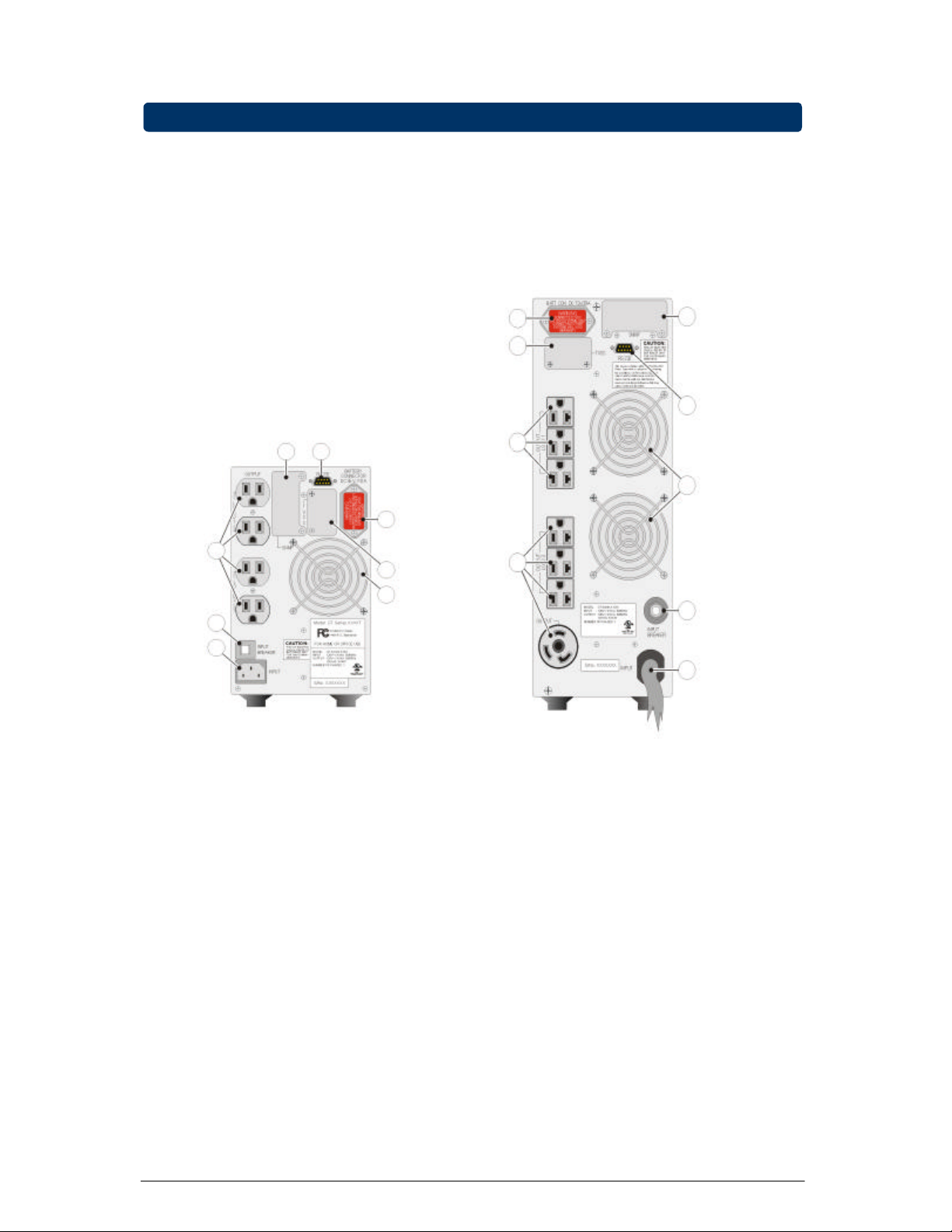
•The UPS has an internal battery supply, with a nominal voltage of (UPS rating /
voltage): 1kVA / 36Vdc, 1.5kVA / 72Vdc, 2kVA / 72Vdc, 3kVA / 72Vdc.
•The appliance outlets may be electrically live, even when the UPS is disconnected
from the utility supply. Dangerous voltages may be present during battery operation.
•Do not open the unit, there are no user serviceable parts inside.
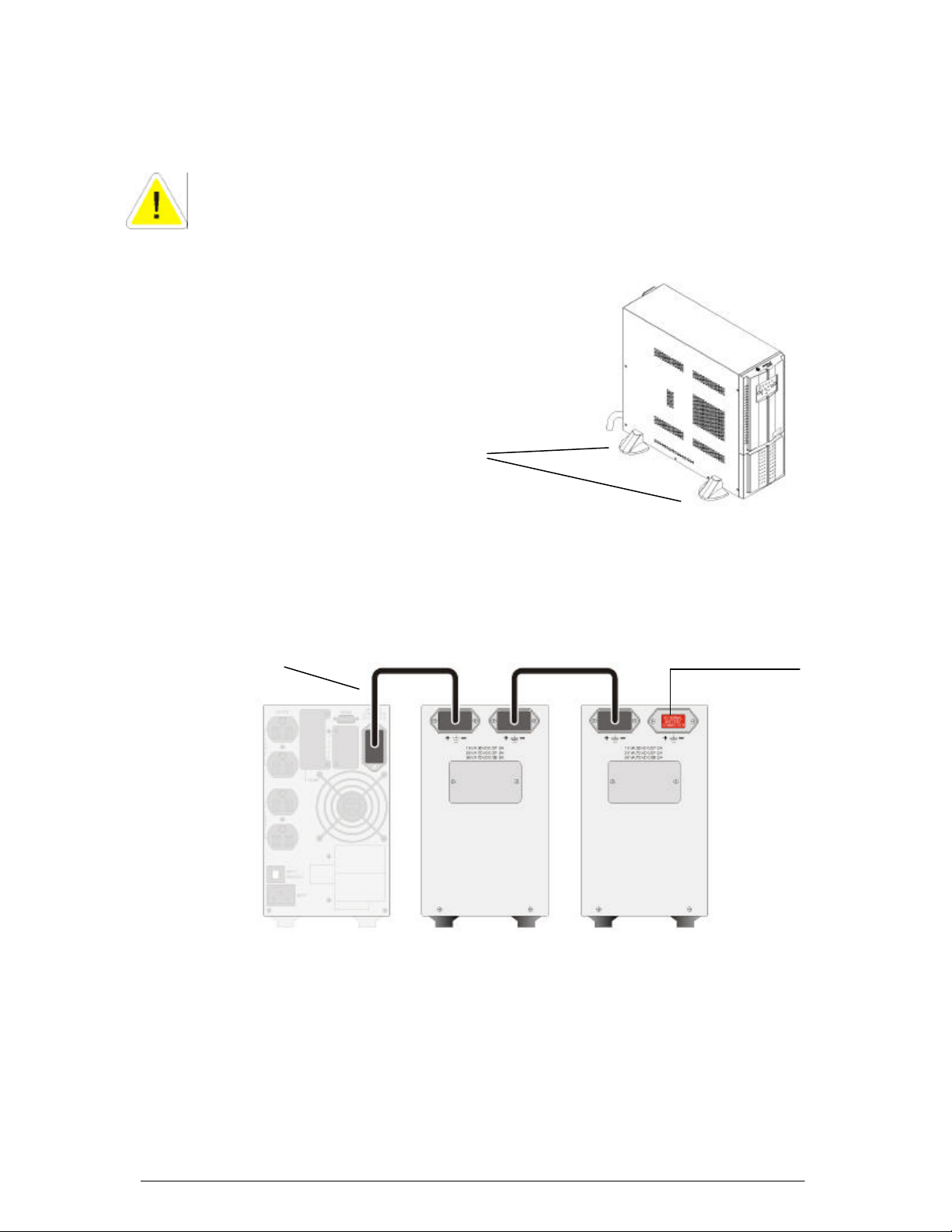
•The batteries must be disconnected during maintenance or service work.
•The UPS contains potentially hazardous voltages.
1.3 Installation
•The unit should be installed by service personnel.
•To reduce the risk of electric shock, install this UPS in a temperature and humidity
controlled indoor area free of conductive contaminants.
•Ambient temperature must not exceed 40°C (104°F). Optimal battery lifetime is
obtained if the ambient temperature does not exceed 30°C (86°F).
•It is important that the unit has adequate ventilation. Maintain air movement around
and through the unit. Do not block the air vents.
•Avoid placing the unit in direct sunlight or near heat sources.
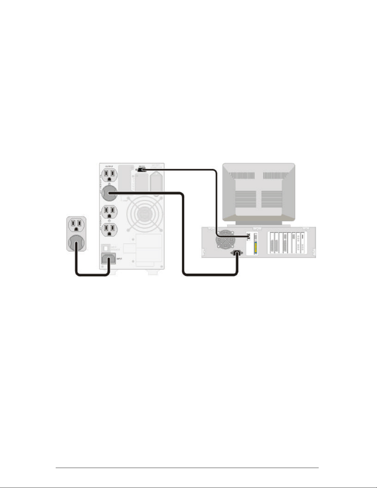
•The UPS should only be powered from a 2-pole 3-wire grounded wall outlet. This
outlet must be easily accessible and located near the UPS.
•Do not use extension cords when connecting the UPS to the utility power supply.
•The AC output of the UPS needs a disconnecting switch such as a breaker which
has to be provided by others.
•The overcurrent protection for the output AC circuit has to be provided by others. All
of our UPS have an electronic protection of AC output short circuit.
•Avoid spilling liquids on or dropping any foreign object into the UPS.
•Do not plug a laser printer or household appliances such as electric heaters or
vacuum cleaners into the UPS. The UPS output is intended to be used only for
electronic loads such as computers and telecommunications equipment.
•Upon installation, it should be ensured that the sum of the leakage currents of the
UPS and the connected loads does not exceed 3.5mA.
•The unit should be operated by properly trained personnel.
1 -Important Safety Instructions

OPM_GTU_TWR_1K0_3K0_XUS_V015 4DE GT Series: User manual rev date 8-11-04
DigitalEnergy
™
GT Series
g
1.4 Batteries
•NOTE: Servicing of batteries should be performed or supervised by personnel
knowledgeable of batteries and the required precautions. Keep unauthorized
personnel away from batteries.
•When replacing the batteries, use only the same number, type and size battery:
GP1270-F2 (CSB) or NP7-12(YUASA) or HR1234W F2(CSB).
•Avoid charging in a sealed container.
•CAUTION:Never dispose of batteries in a fire. The batteries may explode.
•CAUTION: Do not open or mutilate batteries. Released electrolyte is harmfulto the
skin and eyes. It may be toxic. If exposed to electrolyte, wash immediately with
plenty of water.
•CAUTION: A battery can present a risk of electrical shock and high short circuit
current. The following precautions should be observed when workingon batteries:
-Remove watches, rings or other metal objects.
-Use tools with insulated handles.
-Wear rubber gloves and boots.
-Do not lay tools or metal parts on top of batteries.
-Disconnect charging source prior to connecting or disconnecting battery
terminals.
-Determine if the battery is inadvertently grounded. If inadvertently grounded,
remove source of ground. Contact with any part of a grounded battery can result
in electrical shock. The likelihood of such shock will be reduced if such grounds
are removed during installation and maintenance (applicable to UPS and external
battery supply not having a grounded supply circuit).
•Proper disposal or recycling of the batteries is required. Refer to your local codes for
disposal requirements.
1.5 Transport/storage
•No liability can be accepted for any transport damage when the equipment is
shipped in non-original packaging.
•Store the UPS in a dry location with the batteries in a fully charged state. Storage
temperature must be within -20 and +45 °C (-4°F and 113°F). If the unit is stored for
a period exceeding 3 months, optimal battery lifetime is obtained if the storage
temperature does not exceed 25°C (77°F).
•If the unit is stored for an extended period of time, the batteries must be recharged
periodically. Connect the unit to a working wall outlet and recharge the batteries for
24 hours:
-Storage temperature within -20 and +30°C (-4°F and 86°F): every 3 months,
-Storage temperature within -20 and +45°C (-4°F and 113°F): every month.

OPM_GTU_TWR_1K0_3K0_XUS_V015 5DE GT Series: User manual rev date 8-11-04
DigitalEnergy
™
GT Series
g
1.6 FCC IS Interference Statements
1kVA MODEL
Federal Communications Commission Interference Statement
This equipment has been tested and found to comply with the limits for a Class Bdigital
device, pursuant to Part 15 of the FCC Rules. These limits are designed to provide
reasonable protection against harmful interference in a residential installation. This
equipment generates, uses and can radiate radio frequency energy and, if not installed
and used in accordance with the instructions, may cause harmful interference to radio
communications. However, there is no guarantee that interference will not occur in a
particular installation. If this equipment does cause harmful interference to radio or
television reception, which can be determined by turning the equipment off and on, the
user is encouraged to try to correct the interference by one of the following measures:
•Reorient or relocate the receiving antenna.
•Increase the separation between the equipment and receiver.
•Connect the equipment into an outlet on a circuit different from that to which the
receiver is connected.
•Consult the dealer or an experienced radio/TV technician for help.
FCC Caution: To assure continued compliance, use only shielded interface cables
when connecting to computer or peripheral devices. Any changes or modifications not
expressly approved by the party responsible for compliance could void the user’s
authority to operate this equipment.
This device complies with Part 15 of the FCC Rules. Operation is subject to the
following two conditions: (1) this device may not cause harmful interference, and (2) this
device must accept any interference received, including interference that may cause
undesiredoperation.
1.5kVA, 2kVA and 3kVA MODELS
FederalCommunicationsCommission Interference Statement
This equipment has been tested and found to comply with the limits for a Class A digital
device, pursuant to Part 15 of the FCC Rules. These limits are designed to provide
reasonable protection against harmful interference when the equipment isoperated in a
commercial environment. This equipment generates, uses and can radiate radio
frequency energy and, if not installed and used in accordance with the instructions
manual, may cause harmful interference to radio communications. Operation of this
equipment in a residential area is likely to cause harmful interference in which case the
user will be required to correct the interference at his own expense.
FCC Caution: To assure continued compliance, use only shielded interface cables
when connecting to computer or peripheral devices. Any changes or modifications not
expressly approved by the party responsible for comp liance could void the user’s
authority to operate this equipment.

OPM_GTU_TWR_1K0_3K0_XUS_V015 6DE GT Series: User manual rev date 8-11-04
DigitalEnergy
™
GT Series
g
1000VA
7
9
5
8
6
3
2
1
3
3
8
5
9
7
6
2
1
1500 / 2000 /
3000 VA
2.1 Package contents
The packing box contains a Digital Energy™ GT Series-UL UPS, an RS232 data cable, a CD
ROM and this manual. Carefully inspect the packing box and its contents. If any damage is
visible please immediately notify the carrier and/or dealer.
2.2 Location
Please refer to section 1.3 of ‘IMPORTANT SAFETY INSTRUCTIONS’
2.3 Rear panel
1Input
AC utility supply power to the UPS
2Input breaker
Protects the UPS from damage
caused by high input currents
7Communication interface
RS232/dry contact. Allows communi-
cation between computer and UPS.
See chapter 4 for more detailed
information.
3Output receptacles
To connect critical load to the UPS
4Output circuit breaker
Protects the UPS from damage
caused by output overload
8TVSS -Transient Voltage Surge
Suppressor (RJ-45/RJ-11): To
prevent damage caused by surges,
noise and spikes traveling over the
telephone or network line. (Optional)
5DC connector
To connect external battery pack for
extended runtime
6Fan
Electronically controlled cooling fan.
Make sure ventilation air can move
freely around and trough the UPS
9SNMP Slot
An (optional) SNMP adapter can be
plugged into this port for managing the
UPS via the network. See chapter 4
for more detailed information.
2 -Installation
Fig. 2.1 Rear panels

OPM_GTU_TWR_1K0_3K0_XUS_V015 7DE GT Series: User manual rev date 8-11-04
DigitalEnergy
™
GT Series
g
2.4 Installation
The unit should be installed by service personnel.
IMPORTANT:
Before making any connection and switching on the UPS, please check the following
conditions:
•your mains supply is 100/110/120 Volts and 50/60Hz,
•the total power demand of the connected equipment does not exceed the rated
output power of the UPS (indicated on the rating label).
2.4.1 Stable placing of 1.5kVA-3kVA model
To secure a stable placing of the 2-3kVA
models it is advised to set up the UPS with
supporting stands(not included in delivery) as
shown in fig 2.2.
2.4.2 Connectinganexternalbatterypack
1. Before installation, check whether the nominal voltage of battery pack is suitable for
the UPS. The voltages mentioned on the battery connectors should match.
2. Utilize the battery connection cable that came with the battery pack to connect the
battery pack to the UPS as shown in fig. 2.5. The other connector of the battery pack
can be used to connect a second, third etc. pack.
UL 1778 safety requirement:
In order to allow quick removal of the battery power cord in case of emergency, just
plug in the battery power cord; do not fix the connector with screws.
Fig. 2.3 Connecting external battery pack(s) to the UPS
(figure shows 1000VA UPS model)
First battery pack Second battery pack
to third battery pack, etc.
UPS
Fig. 2.2 Set up of 2 -
3kVAmodel
Supporting stands
(not included)
Battery connection cable

OPM_GTU_TWR_1K0_3K0_XUS_V015 8DE GT Series: User manual rev date 8-11-04
DigitalEnergy
™
GT Series
g
2.4.3 Connecting the RS232/dry contact interface
Connect the interface signal cable between the RS-232/dry contact port on the rear
panel of UPS and COM1 or COM2 of your computer if necessary. See fig. 2.4.
Refer to chapter 4 for more information.
2.4.4 Connecting the load
1. Calculate the total power consumption of your loads to ensure that the UPS is able
to supply the required power and overload condition will not happen.
2. Plug the power cord of the equipment into the output receptacles on the rear panel
of the UPS as shown in fig. 2.4. Spread the load ove r the output receptacles as
equally as possible.
CAUTION: Do not connect a laser printer to the UPS.
2.4.5 Connecting to the utility power supply
1000VA:
Use a suitable power cord, and plug it into the input socket (see fig. 2.4)
1500/2000/3000VA:
The UPS is equipped with a fixed input power cord.
1. Plug the input power cord into a working three wire, grounded AC wall outlet.Do not
use extension cords.
2. Turn on the input breaker (if the breaker can be turned on) on the rear panel of UPS.
After that, the fan (in rear panel) will run and, as a front panel test, all LEDs will light
up for about 2-3 seconds. The UPS starts up in ‘STAND-BY’ mode and the battery
will be charged. See fig 2.5.
Fig. 2.4 Connecting the UPS to the utility supply and to the load
(figure shows 1000VA UPS model)

OPM_GTU_TWR_1K0_3K0_XUS_V015 9DE GT Series: User manual rev date 8-11-04
DigitalEnergy
™
GT Series
g
Though the batteries (the internal energy reserve) were fully charged when the UPS left
the factory, they might have lost some energy during transport and/or storage. It is
recommended to allow the UPS to recharge the batteries for at least 6 hours. This way
you ensure that the UPS can provide sufficient runtime in case of a utility power failure.
2.4.6 Checking the site wiring fault LED
When the UPS is still in ‘STAND-BY’ mode, check the site-wiring fault LED. If the UPS
is plugged into an improperly wired ACutility power outlet, this LED flashes as shown in
Fig 2.6.
The detection of site wiring faults includes a missing ground, phase-neutral polarity
reversal and an overloaded neutral circuit. If the LED flashes, unplug the UPS and have
the site wiring checked by a qualified electrician.
This step completes the installation procedure.
Fig. 2.5 Stand-
by mode
Fig. 2.6 Site wiring fault

OPM_GTU_TWR_1K0_3K0_XUS_V015 10 DE GT Series: User manual rev date 8-11-04
DigitalEnergy
™
GT Series
g
8
13
12
11
10
5
3
6
4
1
9
7
2
3.1 Operation Panel
1Switch ‘I/TEST’ -Switches on the UPS
-In ‘ON-LINE’ mode it starts the battery test
-In ‘ON BATTERY’ mode it mutes the buzzer
2Off switch Switches off the UPS
3LED ‘Bypass’ The UPS is in ‘BYPASS’ mode: the incoming utility power is
channeled directly to the load. See also 3.3.5
4LED ‘Line’ Indicates the condition of the utility input power.
Continuouslylighting up: the input power is OK,
Flashing: input voltage is too low, too high, or out of frequency,
Off: blackout or ultra high voltage (>150Vac)
5LED ‘On Line’ The UPS is operating in the (normal) ‘ON LINE’ mode
6LED ‘On Battery’ The UPS is operating in ‘ON BATTERY’ (back-up) mode: utility
power fails, and the internal batteries supply the required
power until either they are depleted or utility power returns.
7Level bar -In ‘ON BATTERY’ mode: shows current battery capacity
-In ‘ON LINE’ mode: showing current load level
8Battery LED Level bar shows current battery capacity
9Load LED Level bar shows current load level
10 Battery low LED The battery is almost depleted
11 Replace battery LED After abattery test the LED shows that the batteries are weak.
Battery replacement is recommended
12 Overload LED The load exceeds the nominal UPS rating. After a short period
of time the UPS will transfer to ‘BYPASS’ mode
13 Fault LED The UPS is faulty
3
-
Operation
Fig. 3.1 Operating panel

OPM_GTU_TWR_1K0_3K0_XUS_V015 11 DE GT Series: User manual rev date 8-11-04
DigitalEnergy
™
GT Series
g
3.2 Start-up
3.2.1 Start-up, utility power available
1Push the ‘I/TEST’-button (1) and hold
for 3 seconds until a short beep is
heard. The bypass LED will shortly light
up. When the LED ‘On Line’ lights up,
the UPS is running in ‘ON LINE’ mode.
2The equipment connected to the UPS
can now be switched on.
3.2.2 Start-up, utility power not available
(cold start or battery start)
1Push the ‘I/TEST’-button (1) and hold
for 3 seconds until a short beep is
heard. The battery LED and LED ‘On
Battery’ will light up. The UPS operates
in ‘ON BATTERY’ mode”: it discharges
the batteries.
3.3 Use:NormalOperation
3.3.1 Normal operation conditions:
•the utility power supply is present and within allowable tolerances,
•the load does notexceed the nominal rating of the UPS and
•the operating temperature is below alarm level
•the UPS is on,
3.3.2 Normal operation indications:
•LEDs ‘Line’, ‘On Line’ and the Load LED
are on
•One or more LEDs on the level bar are on
•the buzze r is silent
3.3.3 UPSself-test
Press the ‘I/TEST’-button (1) when the
UPS is in ‘ON LINE’ mode. The UPS will
shift to ‘ON BATTERY’ mode and
automatically perform a self-test for about
10 seconds (as in fig. 3.5). The self-test
function will check the condition of the
battery. After self-test is finished and test is
O.K, the UPS will return to ‘ON LINE’
mode.
Fig. 3.2 On Line mode
Fig. 3.3 On Battery mode
Fig. 3.4 Normal operation
Fig. 3.5 UPS self test

OPM_GTU_TWR_1K0_3K0_XUS_V015 12 DE GT Series: User manual rev date 8-11-04
DigitalEnergy
™
GT Series
g
3.3.4 Silencing the buzzer
When the UPS is in ‘ON BATTERY’ mode the buzzer can be turned on or off by
pressing the ‘I/TEST’-button (1).
3.3.5 Switching off
1To switch off the UPS push the OFF-button (2) until a short beep is heard. Release
the button after the beep. After a few seconds the UPS will be in ‘STANDBY’ mode:
it will continue keeping the batteries charged. See also fig. 2.5.
2To fully turn off the UPS, and/or if electric isolation is required, unplug the power
cord of the UPS from the wall outlet.
3.4 Use: Abnormal Conditions
3.4.1 On battery
In case of a utility power failure the UPS
will use the energy stored in the battery to
supply the load.
The LED ‘On Battery’ will light and the
buzzer beeps with a 2 seconds interval.
When the utility power returns, the UPS
will switch back to normal operation. In
case of a long power failure the UPS will
stop operating when the batteries have
been depleted (see Chapter 8 -Battery -
Back-up Time).
3.4.2 Battery low
The batteries are nearly discharged during
battery operation (see 3.4.1).
The LED ‘On Battery’ and the ‘Battery Low’
LED will light and the buzzer beeps with a
1.5 seconds interval, Controlled shutdown
of any computer equipment is absolutely
necessary at this point
3.4.3 Overload
The demanded power exceeds the normal
capacity of the UPS.
The Overload LED will light and the buzzer
sounds continuously.
You are advised to unplug some load as
soon as possible. If an overload condition
persists, the UPS may eventually switch to
bypass operation. If this is not possible
(UPS was operating on battery during
utility failure, bypass is not available) the
UPS output power may be lost.
Fig. 3.6
On battery
Fig. 3.8 Overload
Fig. 3.7 Battery low

OPM_GTU_TWR_1K0_3K0_XUS_V015 13 DE GT Series: User manual rev date 8-11-04
DigitalEnergy
™
GT Series
g
3.4.4 Bypass operation
If the UPS is unable to deliver the
demanded output power due to overload
or over-temperature, the load is switched
directly to the utility supply.
The LED ‘Bypass’ will light, and the buzzer
will sound continuously.
The UPS will switch back to ‘ON LINE’
mode (normal operation) when the load
and/or temperature conditions returned to
normal.
If a power failure occurs during bypass
operation, the UPS will switch to battery
operation and eventually, when the batteries
are depleted, UPS output power is lost. If the UPS functions under overload or over-
temperature conditions it may not be able to protect the load.
3.4.5 Replace battery
The batteries are aged and must be
replaced as soon as possible to ensure fu ll
protection for your equipment.
The ‘Replace Battery’ LED lights and the
buzzer sends out three beeps every hour,
until the batteries have been replaced.
3.4.6 Short circuit
In case of a short circuit in the load during
‘ON-LINE’ mode or ‘ON BATTERY’ mode
the UPS will shut down and output power
is lost.
The Fault LED will light and the buzzer will
sound continuously.
The situation will be cleared if the short
circuit is removed.
If the short circuit situation happens during
‘BYPASS’ mode, the input breaker will trip
and the UPS output power is lost.
Fig. 3.9 Bypass operation
Fig. 3.11 Short circuit
Fig. 3.10 Replace battery

OPM_GTU_TWR_1K0_3K0_XUS_V015 14 DE GT Series: User manual rev date 8-11-04
DigitalEnergy
™
GT Series
g
4.1 Description
The GT Series UPS is equipped with a communications interface, providing RS232 and dry
contact protocols in one sub-D 9-pin female connector located at the rear of the unit. The
communication port on the UPS can be connected to a computer. This port allows the
computer to monitor the UPS status and control the operation of the UPS in some conditions.
Using proper UPS management software and cable, the UPS can be managed in
LAN/intranet/internet environments.
Some computers may have a special connector to link this communication port, or require a
special plug-in card, or need a special UPS monitoring software. For specific information on
Digital Energy™GTSeries connectivityproducts please contact your local dealer or Internet:
http://www.geindustrial.com/cwc/products?famid=46&lang=en_US
The dry contacts (4.3) and (optional) SNMP plug-in card (4.4) can be connected at the same
time. However, if both are operating simultaneously the remote shutdown facility for the dry
contacts will not be available. Battery low and AC failure functions remain unaffected.
The pin assignment of the interface connector is defined as follows:
ASSIGNMENT DESCRIPTION
PIN RS-232 Dry Contact
1Low battery (Open collector)
2UPS TxD (typical RS-232 level)
3UPS RxD (typical RS-232 level)
Remote shutdown (5~12V)
4Reserved for PNP
5GND GND
6Reserved for PNP Reserved
7Reserved for PNP Reserved
8Utility Fail (Open collector)
9
Pin Assignment Open Collector Circuit
The maximum voltage and current on pin 1,8 is 30VDC, 10mA.
4 -Communication

OPM_GTU_TWR_1K0_3K0_XUS_V015 15 DE GT Series: User manual rev date 8-11-04
DigitalEnergy
™
GT Series
g
4.2 RS232
The RS-232 communication port provides the following functions:
1 -Monitoring charger status
2 -Monitoring battery status and condition
3 -Monitoring inverter status
4 -Monitoring UPS status
5 -Monitoring the AC utility power status
6 -Turn on/off UPS on schedule for power saving
7 -Adjust transfer voltage
Pin Assignment:
Pin 2 :PC receives line RS-232 data from UPS.
Pin 3 :PC transmits line RS-232 data to UPS.
Pin 5 :Signal ground.
Pin 4,6,7 :Reserved for plug and play function.
The UPS data is provided at 2400 bps baud rate and made up of 8-bit, 1 stop-bit and no parity
bit. All information is encoded in ASCII format.
Hardware:Baudrate 2400 bps
Data length 8 bits
Stop bit 1 bit
Parity none
Cabling:
Standard sub-D 9 cable (UPS side: male, PC side: female)
4.3 DryContact
Its major functions are some or all of the following:
1 -to broadcast a warning when the AC utility power fails.
2 -to save open files before the battery is exhausted.
3 -to turn off the UPS via computer(s).
Pin Assignment:
Pin 1 :Normally open. When the battery voltage level is low, pin 1 and pin 5 are
connected together via a photo coupler.
Pin 3 :UPS will shut down when a high level (5~12V) is applied for at least 3.8 seconds.
Pin 5 :Signal ground.
Pin 6,7 :Reserved.
Pin 8 :Normally open. When the AC utility fails, pin 8 and pin 5 are connected together via
a photo coupler.
Cabling:
A special cable must be used with a pin assignment as follows:
PC (female) UPS (male)
Pin 1 -----------------------Pin1(BatteryLow)
Pin 3 -----------------------Pin5(GND)
Pin 4 -----------------------Pin3(Shutdown)
Pin 7 -----------------------Pin6
Pin 7 -----------------------Pin7
Pin 8 -----------------------Pin8(ACFail)

OPM_GTU_TWR_1K0_3K0_XUS_V015 16 DE GT Series: User manual rev date 8-11-04
DigitalEnergy
™
GT Series
g
4.4 SNMP Plug-in Card (optional)
SNMP (Simple NetworkManagement Protocol) is the most popular protocol in the network. Via
NMS (Network Management Station) you can detect the status of all facilities in the network.
An SNMP Interface Card can be plugged into the built-in SNMP slot on rear panel of the UPS
(please refer to fig. 2-1). This optional interface unit can integrate the UPS into the network
allowing you to easily monitoring the UPS status.
NOTE: Once you install the SNMP card in the UPS, you cannot get any information from
the UPS via RS232. i.e. only either an SNMP card or the RS232 port can be used as a
communication interface!
The SNMP card also supports SHTTP protocol, you can use browser Microsoft IE or Netscape
Communicator to monitor or configure the UPS. Besides, the SNMP card supports Telnet and
FTP for remote monitoring and firmware upgrading.
Specifications:
1 -Auto detecting 10/100M Network speed.
2 -Supporting protocol: TCP/IP, UDP, HTTP, ICMP, ARP, TELNET, BOOTP, DHCP, FTP
and SNMPv1.
3 -Remotefirmware upgradeableand configurable.
4 -Web server built-in, allow monitoring/controlling UPS via browser.
5 -VT100 terminal mode or Telnet to configure SNMP.
Functions:
1 -Schedule: Shutdown/Restart UPS, testing and control outlets.
2 -Testing: Scheduled testing of the battery can insure that the UPS will operate properly
during autility powerfailure.
3 -Event log: Auto-record the power event.
4 -Historical records: Keep records of UPS status in specified interval.
5 -Eventhandling:configure special actionforeach power event to meet your requirements.
6 -On/Off UPS: set-up the power on/off timer.
7 -Outlet control: configure UPS outlets.

OPM_GTU_TWR_1K0_3K0_XUS_V015 17 DE GT Series: User manual rev date 8-11-04
DigitalEnergy
™
GT Series
g
Apart from the SNMP-option described in 4.4 the following options are possible:
5.1 Extended Runtime
Extended runtime can be obtained by connecting a separate battery extension module to the
UPS. The additional batteries increase the runtime and recharging time for the unit, all other
operational information is the same as for standard models.
5.2 TVSS (Transient Voltage Surge Suppressor)
RJ-45/RJ-11 Surge Protector.
To prevent damage caused by surges, noise and spikes traveling over the telephone line or
network line.
6.1 General Maintenance
Apart from battery servicing, the UPS is virtually maintenance free. Take care of proper
environmental conditions and keep air inlets/outlets free of dust. Please read 1.3.
6.2 Batteries -General
The service life of the battery is from 3 to 6 years, depending on the operating conditions
(mainly temperature and number of discharge cycles).
As a healthy battery is critical to the performance of the UPS, it is advised to regularly perform
a battery test to ensure failsafe operation (see section 3.3.3). When the condition of the battery
is critical, a 'replace battery'alarm will be activated (see 3.4.5). Have the batteries replaced as
soonas possible.See 6.3.
6.3 Batteries -Replacement
•WARNING: first read the safety rules in sections 1.1, 1.2 and 1.4.
•Servicing of batteries should be performed or supervised by personnel
knowledgeable of batteries and the required precautions. Keep unauthorized
personnel away from batteries.
6.4 Recycling the UPS at the end of service life
GE Digital Energy, in compliance with environment protection recommends that the
UPS equipment, at the end of its service life, must be recycled conforming to the local
applicable regulations.
5 -Optional Features
6 -Maintenance

OPM_GTU_TWR_1K0_3K0_XUS_V015 18 DE GT Series: User manual rev date 8-11-04
DigitalEnergy
™
GT Series
g
Whenever a malfunction occurs, first check external factors (e.g. connections, temperature,
humidity or load) to determine whether the problem is caused by the unit itself or by its
environment. Subsequently check the thermal circuit breaker: it may be tripped. If so: reset it
and be sure that the UPS is not overloaded.
The following chart is a simple troubleshooting checklist only. If the suggested solution does
not succeed, or if the information is insufficient to solve the problem, please contact your dealer
or consulthttp://www.geindustrial.com/industrialsystems/gede/index.html .
PROBLEM POSSIBLE CAUSE SOLUTION
UPS overload Reduce load, reset breakerInput Circuit Breaker tripped System failure Contact your dealer or consult
www.gedigitalenergy.com
UPS will not switch on Line cord not connected Connect line cord
Dead wall socket outlet, or
mains voltage out of limits Contact qualified electrician
Tripped input circuit breaker Check whether UPS is not
overloaded,resetbreaker
Battery voltage too low Allow UPS to recharge the battery
Batteriesnotconnected Contact your dealer or consult
www.gedigitalenergy.com
UPS has no output UPS over-temperature Allow UPS to cool down
Utility failure, battery depleted Wait until utility power returns
Input breaker tripped See above
LED ‘Fault’ lights up, buzzer
sounds continuously Internal UPS failure Contact your dealer or consult
www.gedigitalenergy.com
LED ‘Fault’ flashes Wiringfault(L-N reversed) Have site wiring checked by
qualified electrician
LED ‘Battery low’ lights up,
buzzerbeeps2x/sec. Battery is close to being
exhausted during utility failure The UPS output will be lost soon.
Shut down the load in an orderly
manner
LED ‘Replace battery’ lights up,
buzzersoundscontinuously Battery test just after a utility
failure(‘falsealarm’) Allow the UPS to rechargethe
battery for approx. 8 hours, then
repeat the battery test
Battery is close to being worn
out Allow the UPS to recharge the
battery for approx. 8 hours, then
perform battery test. If the alarm
persists, consider battery
replacement
LED‘Overload’lights up,
buzzersoundscontinuously UPS is overloaded Reduce load, e.g. by unplugging
non-critical load
Buzzer sounds continuously:
over-temperature Ambient temp. too high, or
ventilation blocked Reduce ambient temperature,
enhance ventilation
Fan failureHave the fan replaced
UPS cannot be linked to
computer Communication cable
defective Checkcable
Transmitting rate fault Adjusttransmittingrate
Communication port fault Check COM1/COM2 configuration
of the computer
7 -Troubleshooting

OPM_GTU_TWR_1K0_3K0_XUS_V015 19 DE GT Series: User manual rev date 8-11-04
DigitalEnergy
™
GT Series
g
GT Model 1000T UL 1500T UL 2000T UL
3000T UL
Capacity 1kVA/800W 1.5kVA/ 1200 W
2kVA/1600W
3kVA/2400W
Rated Voltage 100V, 110V, 120V
Voltage Range 80V~138V (full load); 65V~80V(70% load)
Frequency 50Hz / 60Hz (± 4.8 Hz)
Input
Power Factor ≥0.97
Voltage 100V, 110V, 120V
Frequency 50Hz / 60Hz
Voltage Regulation ± 2%
FrequencyAccuracy ± 0.05 Hz
WaveForm pure sine wave
Transient Response ± 8% (10%∼90% linear load)
THD (linear load) ≤3% ≤3% ≤4%
THD (computer load) ≤6%
Overload Capacity 105%~125% for 3mins; 125%~150% for 30secs; >150% for 1sec
Crest Factor 3:1
Output
Efficiency (AC-AC) ≥87%
Outlet Receptacles NEMA TYPE
Battery Voltage 36V 72V 72V
Battery Type (Lead acid)
12V/7Ah12V/7Ah12V/9Ah
Back-up Time
(Typical)5mins
Battery
Recharge Time 4~6 hours after complete discharge to recover 90%
Transfer
Time Transfer Time zero
LED Status On-line / Bypass / On-battery / Overload / Battery Low / Fault
Battery Replace / Battery Level / Load Level
LED Alarm buzzer
DB9 RS232/dry contact
Interface SNMP Slot internal
Noise (At 1 Meter) 40dB(A) 42dB(A) 45dB(A)
Operating
Temperature 0~40°C (32~104°F)
Environment
Humidity 0%~90% (non-condensing)
Safety UL/cUL
EMC FCC Class A (2,3kVA) /B (1kVA)
CISPR PUB 22 Class B; TUV/EMC; CE (1kVA)
CISPR PUB 22 Class A (2, 3kVA)
Safety
Approval
Lightning IEEE 62.41 Category A
Battery Start yes
Extended Battery
Bank yes (optional for longer runtime)
Others
Long Time Model yes (optional)
Dimensions
(W×D×H) 140x366x242 mm
5.5x14.4x9.5 inch 140x425x373mm
5.5x16.7x14.7 inch
Appearance Weight 15 kg
33lbs 30 kg
66 lbs 30 kg
66 lbs
8 -Specifications
This manual suits for next models
5
Table of contents
Other GE UPS manuals

GE
GE 225 User manual

GE
GE Digital Energy LP 11U Instruction Manual

GE
GE Digital Energy LP 33 Series User manual

GE
GE GT6000 User manual

GE
GE 1000 VA User manual

GE
GE Digital Energy SG 400 kVA User manual

GE
GE SG Series User manual

GE
GE Uninterruptible Power Supply User manual

GE
GE Match User manual

GE
GE Digital Energy SitePro 400 VAC CESeries 7 User manual

GE
GE SG 225 User manual

GE
GE SG Series 400 User manual

GE
GE LanPro 11 U User manual

GE
GE GT Series User manual

GE
GE Amersham Imager 600 User manual

GE
GE Digital Energy LP 33 Series User manual

GE
GE LP 33U Series User manual

GE
GE Digital Energy LP 31 Series User manual

GE
GE SG 300 User manual

GE
GE lp33 20 series User manual