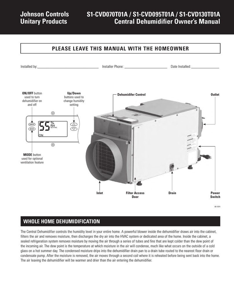
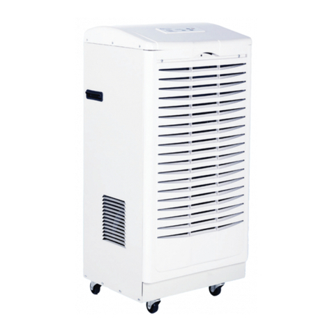
Field Controls FC-60DH User manual

www.eldcontrols.com
Please retain these instructions after installation.
This device MUST be installed by a qualied agency in accordance with the manufacturer's installation instructions. The denition of
a qualied agency is: any individual, rm, corporation or company which either in person or through a representative is engaged
in, and is responsible for, the installation and operation of HVAC appliances, who is experienced in such work, familiar with all the
precautions required, and has complied with all the requirements of the authority having jurisdiction.
Installation Date:
Installed By: Phone:
Models: FC-60DH, FC-85DH, FC-120DH
DEHUMIDIFIER
READ THESE INSTRUCTIONS CAREFULLY AND COMPLETELY
READ THESE INSTRUCTIONS CAREFULLY AND COMPLETELY
BEFORE PROCEEDING WITH THE INSTALLATION.
BEFORE PROCEEDING WITH THE INSTALLATION.
P/N 780107800 09/21 Rev A

Page 2 of 12
• Always connect your dehumidier using a grounded, dedicated electrical connection that is GFCI protected
• Always connect your dehumidier using a grounded, dedicated electrical connection that is GFCI protected
with at least 15 amp capacity.
with at least 15 amp capacity.
• The use of any other type of wiring will void your warranty.
• The use of any other type of wiring will void your warranty.
• Install dehumidier according to all applicable local, state, and national codes
• Install dehumidier according to all applicable local, state, and national codes
• Be sure to follow your GFCI manufacturer’s maintenance instructions. You will typically need to test the
• Be sure to follow your GFCI manufacturer’s maintenance instructions. You will typically need to test the
operation of the trip circuit monthly.
operation of the trip circuit monthly.
• For ease of testing and operation, it may be helpful to put the test switch and indicator lights in a convenient
• For ease of testing and operation, it may be helpful to put the test switch and indicator lights in a convenient
location.
location.
• Your dehumidier should only be repaired by a qualied technician.
• Your dehumidier should only be repaired by a qualied technician.
• Do not insert objects or your ngers into the inlet or discharge.
• Do not insert objects or your ngers into the inlet or discharge.
• Do not use water to clean the exterior of the dehumidier. To clean unit, unplug from power, then use a damp
• Do not use water to clean the exterior of the dehumidier. To clean unit, unplug from power, then use a damp
cloth to wipe the exterior.
cloth to wipe the exterior.
• Do not stand on dehumidier or place objects on it.
• Do not stand on dehumidier or place objects on it.
• Do not use with extension cord or plug adapter.
• Do not use with extension cord or plug adapter.
• Unless otherwise noted, all maintenance should be done with the unit powered o.
• Unless otherwise noted, all maintenance should be done with the unit powered o.
P/N 780107800 09/21 RevA
IMPORTANT NOTES
MODEL FC-60DH FC-85DH FC-120DH
Capacity @ 80°F/60%RH: 60 pints per day 85 pints per day 120 pints per day
Airow @ 0.0”SP 155CFM 185CFM 300CFM
Operating Temp Range 33-105¯F 33-105¯F 33-105¯F
Operating Relative Humidity Range 36%-90% 36%-90% 36%-90%
COP 2.451 L/kWh 2.71 L/kWh 2.8 L/kWh
Refrigerant R410A R410A R410A
Amperage Usage 4.05 Amps 5.3 Amps 7.6 Amps
Power Supply 115V/60Hz/Single Phase 115V/60Hz/Single Phase 115V/60Hz/Single Phase
Outlet Requirement 15 Amp, 3 prong, GFCI 15 Amp, 3 prong, GFCI 15 Amp, 3 prong, GFCI
Sound Level 59 dBa 59 dBa 60 dBa
Dimensions LxWxH 21.7” x 12” x 12” 21.7” x 12” x 12” 23.75” x 14” x 16”
ETL Listed Yes Yes Yes
SPECIFICATIONS

Page 3 of 12
INSTALLATION REQUIREMENTS
INSTALLATION REQUIREMENTS
P/N 780107800 09/21 RevA
• The area where the dehumidier is located should be sealed with a vapor barrier.
• If the unit is installed in a crawl space, all vents should be sealed.
• For proper ventilation, neither the inlet or discharge should be positioned against a wall. The inlet
needs a minimum of 12” clearance and the discharge requires a minimum of 36” clearance.
• For the best air diusion, install the unit so that a side panel faces the wall.
• Field Controls dehumidiers are only intended for operation when the unit is upright and level with
the feet on the ground (unless using a Field Controls Hanging Kit).
HOW IT WORKS
HOW IT WORKS
Field Controls dehumidiers use an integrated humidistat to monitor the conditioned space.When the
relative humidity goes above the selected setpoint, the dehumidier will energize. Air is then drawn
across an evaporator coil, which is cooler than the dew point of air. This means moisture will condense
out of the air. The air is then reheated through the condenser coil and distributed back into the room.
INSTALLATION
INSTALLATION
1. Place dehumidier on a level surface.
• Do not place unit directly on vapor barrier. For example, use blocks or pavers to create a level
surface.
• If unit has been turned or ipped so that the compressor did not remain upright, place the
unit on a level surface and wait a minimum of 2 hours before proceeding.
2. Set up the drain line
• The drain line should be routed to a suitable drain on the outside.
• THE DRAIN MUST FLOW DOWN WITH NO LOOPS OR DIPS.
• Recommended Drain Option- Transition to PVC Pipe
1. Cut a piece of 3/4”OD PVC that is approx. 6” long.
2. Insert cut PVC into a 3/4” elbow.
3. Attach PVC+elbow to a 3/4”OD length of PVC to drain.
Keep the length of PVC as short as possible.
4. Insert the open end of dehumidier drain tube into 6”
piece of PVC so that it does not extend into elbow tting.
5. For a proper ow, a minimum downward slop of 1” per
10’ run is required.
6. Support the PVC tubing so that it maintains a smooth downward ow to drain.
3. Plug unit into a dedicated 15 amp GFCI protected outlet.

Page 4 of 12
P/N 780107800 09/21 RevA
KEY FUNCTIONS
KEY FUNCTIONS
1. Power Key
• Use this button to turn the dehumidier on and o.
• Press once to turn machine on. You will hear two beeps and the light will illuminate
green (solid or ashing depending on mode).
• Press the power button a second time and you will hear one beep as the machine shuts
down. Note that there is a 1 minute fan delay.
2. Arrow Buttons
• Use the up and down arrows to set the desired humidity setpoint on the display screen.
• The setpoint can be any number between 36%-90%. When the indoor humidity is higher
than the setpoint, the unit will operate.
* Keep in mind that the displayed humidity levels are approximate (+/-5%)
3. Continuous Mode
• To set the unit to run continuously regardless of humidity,
simply use the down arrow key to set the humidity below 36%.
• The continuous light will illuminate green and the display will show “CO”.
• To switch back to normal humidistat operation, use the arrow keys to move the setpoint
above 36%.
4. Auxilary Terminals A5/A6
• The A5/A6 on the terminal strip can be used as a safety switch for an external oat switch or
condensate pump.
• It should be set to N/O (normally open) at the accessory oat switch.
• If an E4 error occurs immediately, switch the wiring to N/C (normally closed) on the external
device. Note that you may need to unplug the unit to reset the error code.

Page 5 of 12 P/N 780107800 09/21 RevA
INDICATOR LIGHTS
INDICATOR LIGHTS
1. Humidity Display Screen
• The display screen has two functions:
1. When the unit is powered on, it shows the humidity of the space
2. When setting the desired humidity level, the screen will show the set point. After a brief
delay, it will revert to current humidity of the space.
2. Power Indicator Light
• This light indicates that the unit is properly powered on and ready to operate.
• Always make sure the unit is “off” prior to performing any service, unless otherwise
indicated.
• If the humidity is above the setpoint, the light will be solid green and the machine will
operate.
• If the humidity is below the setpoint, the unit will be in standby mode and the light will be
ashing.
3. Continuous Mode/Auto Defrost Light
• When the light illuminates green, it indicates that the dehumidifier is set to continuous
operation mode.
• When the light illuminates red, it means the unit is in auto defrost mode and clearing the
evaporator coils of any ice buildup.
4. Compressor Light
• When the light illuminates red, it indicates the compressor has been initiated but is
currently warming up.
• Once the light switches to green, it means the compressor is currently in working status.

Page 6 of 12
P/N 780107800 09/21 RevA
REMOTE CONTROL INSTRUCTIONS
REMOTE CONTROL INSTRUCTIONS
Field Controls Dehumidiers can be controlled using an optional remote accessory. The remote
connects to your dehumidier via a 25’CAT 5 cable, with the integrated sensor giving you mul-
tiple options for monitoring surrounding conditions.
Example #1- Install the dehumidier in the laundry room and
duct it into the living room. Mount the remote in the living room and use the remote sensor.
Example #2- Install the dehumidier in your crawl space with
the remote mounted in your garage.
NOTE: The symbols indicated
below only show when the
remote is powered on.
1. On/O (Power) Button
Press the on/o button and the
machine will start running. Press
the button again to turn the
machine o.
2. Up Button/ Down Button
Use the up and down arrows to
adjust the humidity level.
3. Mode
Use the mode button to switch
between dehumidier and a ducted
application.
• The symbol on the display indicates the sensor on the remote control is being utilized.
• The symbol on the display indicates the sensor on the dehumidier is being utilized.
4. Temperature
The T button changes the temperature reading on your remote. The remote comes from the
factory in Celsius. Press this button once to switch to Fahrenheit.
5. Continuous
Press this button to switch the unit into continuous mode. “CONT.” will appear on the display
screen.
6. Drain Pump
This button is not used for these models.

Page 7 of 12 P/N 780107800 09/21 RevA
OPERATING INSTRUCTIONS
OPERATING INSTRUCTIONS
1. Start the machine
• Press the power key to turn the dehumidier on.
2. Adjust the settings
• Use the up and down arrow keys to adjust your desired setpoint (typically 50-55%)
3. Stop the machine
•Press the power button again and the dehumidier will stop. Note that the fan will continue
to operate for 1 minute after the unit has shut o. DO NOT DISCONNECT THE POWER CORD TO
FORCE THE UNIT TO STOP.
4. Water Drainage
• During normal operation, the dehumidier will automatically drain due to gravity.
• If you want to move or store the machine, wait at least 10 minutes to allow the unit to
completely defrost.
•Once defrosted, lean the dehumidier gently towards the drain to ensure it is completely dry.
UNIT DIAGRAM
UNIT DIAGRAM

Page 8 of 12
P/N 780107800 09/21 RevA
MAINTENANCE
MAINTENANCE
WARNING: Always unplug the unit before doing any maintenance.
Cleaning the Machine Body
Use a soft, damp cloth to clean the exterior of unit. Do not use any soap or solvents
Coil Maintenance
Once per year, clean the coils with an approved coil cleaner. The coil cleaner should be a
self-rinsing, foaming, cleaner, such as WEB® Coil Cleaner.
Cleaning the Filter
1. Unplug the unit.
2. For PreFilter:
a. Remove prelter from inlet of machine.
b. Vacuum or wash with warm water (no soap).
3. For MERV-10/HEPA/Carbon Filters:
a. Replace as necessary- we recommend checking the lter at least 1x/year
Electrical Access
• Unscrew the 13 screws on the side panel.
• Remove the screw on the control board cover.

Page 9 of 12 P/N 780107800 09/21 RevA
• Mix a 16 ounce solution of bleach (1 oz bleach + 15 oz water) OR vinegar (4 oz white vinegar
+ 12 oz water).
• Remove lter(s) so you have access to the drain tray.
• Disconnect power to dehumidier.
• Pour the cleaning solution into the drain tray at the base of the coils. If any cleaning solution
gets on the coils, ush with water.
• Allow solution to soak for 15 minutes.
• Pour in 16-32 ounces of clean water to ush out the drain line.
Cleaning the Gravity Drain
Complete about once per year, depending on environment
DEHUMIDIFIER STORAGE
DEHUMIDIFIER STORAGE
If the unit will be stored for an extended period of time, complete the following steps:
1. Turn o the unit and allow it to dry.
2. Wrap and secure the power cord.
3. Cover the lter mesh.
4. Store in a clean, dry space.
DUCTED APPLICATIONS
DUCTED APPLICATIONS
Ducting the dehumidier allows the unit to be in one room while conditioning an adjacent
room. Both the inlet/return grille and the supply grille are designed for 10” ex ducting.
Ducting Installation Notes
• Be sure to secure the ducting with tie wrap.
• Maximum total length of duct run = 10’
• Inlet and outlet duct adapters are optional
accessories
Duct Adapter Installation
• Screw in the 4 screws on each duct adapter.
Flex Duct Installation
• Slide ducting over adapter and secure
with tie wrap or clamps

Page 10 of 12
P/N 780107800 09/21 RevA
TROUBLESHOOTING
TROUBLESHOOTING
SYMPTOM CAUSE SOLUTION
Display is Blank
Poor Connection Verify that both ends of the power cord are
plugged in
Power Outage Reset power
No AIrow
Filter is dirty Clean the lter
Air inlet or outlet is blocked Clear the blockage
Error Code: E1 Humidity Sensor or
Communication Error
Check to ensure that the sensor wire is
concceted at both ends. If no issues are
visible, the sensor may be faulty.
Error Code: E4 Problem with Pump
Verify that the pump is properly installed and
functioning. If so, unplug the unit for two min-
utes, then restart.
Error Code: LO Room Temperature is below 33°F
Increase the room temperature so it is within
operating range (above 33°F). If error still
displays, check sensor.
Error Code: HI Room Temperature is above 105°F
Decrease the room temperature so it is within
operating range (below 105°F). If
error still displays, check the sensor.
Tripped GFCI
Outlet or
Breaker
Not a dedicated circuit
Identify all sources connected to outlet and
conrm source of trip. If it is dehumidier,
contact technical support. If not, move dehu-
midier to dedicated circuit for future use.
Defective GFCI Outlet Replace Outlet
Dirt, Dust, or Moisture on Outlet Clean or replace outlet, as necessary.
Lightning or External
Electrical Surge Reset or Replace Breaker.GFCI, as necessary.
Possible Dehumidier Issue If none of above options work, contact
technical support.

Page 11 of 12 P/N 780107800 09/21 RevA
SPARE PARTS
SPARE PARTS
PART # MODEL DESCRIPTION FC-60DH FC-85DH FC-120DH
602609204 SM10C 10” Round Return Supply Collars (set of 2) Small X X -
602609205 LG10C 10” Round Return Supply Collars (set of 2) Large - - X
602609206 WHD1-RCK Remote Control Kit X X X
602609207 WHD2-HK Hanging Kit Assembly X X X
602609701 SM10PF WHD Prelter replacement Small X X -
602609702 LG10PF WHD Prelter replacement Large - - X
602609703 SMM10 WHD MERV10 Filter replacement Small X X -
602609704 LGM10 WHD MERV10 Filter replacement Large - - X

Phone: 252.522.3031 • Fax: 252.522.0214
www.fieldcontrols.com
This manual may be downloaded and printed from the Field Controls website (www.eldcontrols.com)
This manual may be downloaded and printed from the Field Controls website (www.eldcontrols.com)
WARRANTY
WARRANTY
For warranty information about this or any Field Controls product, visit:
For warranty information about this or any Field Controls product, visit:
www.eldcontrols.com
www.eldcontrols.com
Field Controls Technical Support
Field Controls Technical Support
1.800.742.8368
1.800.742.8368
eldtec@eldcontrols.com
eldtec@eldcontrols.com
© Field Controls, LLC P/N 780107800 09/21 RevA
This manual suits for next models
2
Table of contents
