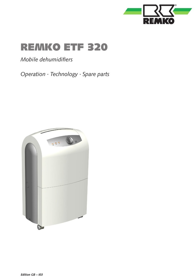
REMKO AMT Series User manual

Edition GB – R12
REMKO AMT
Dehumidifier
Operation · Technology ·Spare Parts


Contents
Made by REMKO
Before commissioning/use of the equipment, these
operating instructions must be read carefully!
These instructions are a part of the device and must thus always be
kept in the direct vicinity of the mounting site or on the device itself.
Subject to changes, errors and typographical errors excepted.
Dehumidification 4
Safety Instruction 6
Proper use 7
Customer Service and Warranty 7
Environmental Protection and Recycling 7
Equipment Description 8
Installation 9
Commissioning 10
Shutdown 12
Unit transport 13
Maintenance and Service 13
Trouble Shooting 14
Electrical wiring diagram 15
Exploded view AMT 40-E 16
Spare parts list AMT 40-E 17
Exploded view AMT 55-E + 80-E 18
Spare Parts List AMT 55-E + 80-E 19
Exploded view AMT 110-E 20
Spare parts list AMT 110-E 21
Maintenance log 22
Technical Data 23
3

This shows that the rate of corro-
sion below 50% relative humidity
(R H) is insignificant and below
40% R H can be disregarded.
From 60% R H, the rate of corro-
sion increases considerably. This
moisture damage limit applies also
to numerous other materials, e.g.
powders, packaging, wood or elec-
tronic units.
Buildings can be dried out in differ-
ent ways:
1.
By heating and air exchange:
The room air is heated to absorb
moisture in order to then be dis-
charged to the atmosphere. The
total input energy is lost with
the discharged, moist air.
2.
By dehumidification:
The moist air in an enclosed
room is continuously dehumidi-
fied by the condensation princi-
ple.
The interrelated processes that
take place during dehumidification
are based on physical laws.
These are to be illustrated here in
simplified form in order to explain
the principle of dehumidification.
The use of
REMKO dehumidifiers
– No matter how well windows
and doors are insulated, damp
and moisture can penetrate
even through thick concrete
walls.
– The water volumes required for
binding concrete, mortar, plas-
ter, etc. are diffused out initially
after 1-2 months under certain
circumstances.
– Even moisture that has penetrat-
ed masonry following high wa-
ter or flooding, is only released
very slowly.
– This applies similarly, e.g. also to
moisture contained in deposited
materials.
The moisture (water vapour) es-
caping from buildings or materials
is absorbed by the ambient air. This
increases their moisture content
and ultimately results in corrosion,
mould, rot, peeling of paint coat-
ings and other unwanted moisture
damage.
The diagram opposite shows an
example of the rate of corrosion,
e.g. for metal at different humidity
levels.
Dehumidification
In terms of energy consumption,
dehumidification has one decisive
advantage:
Energy expenditure is restricted
solely to the existing room volume.
The mechanical heat released
through the dehumidification proc-
ess is returned to the room.
With correct use, the dehumidi-
fier only uses about 25% of the
energy that would be needed for
the „heating and ventilation”
principle.
The relative humidity
Our ambient air is a gas mixture
and contains always a certain
amount of water in the form of
water vapour. This water volume is
expressed in g per kg dry air (abso-
lute water content).
1m3air
weighs about 1,2 kg at 20 ° C
Depending on the temperature,
each kg of air is only able to ab-
sorb a certain amount of water va-
pour. When this absorptive capac-
ity is reached, reference is made to
“saturated” air; this has a relative
humidity of (R H) 100%.
Relative humidity is therefore un-
derstood to be the ratio between
the amount of water vapour cur-
rently contained in the air and the
maximum water vapour volume at
the same temperature.
The ability of air to absorb water
vapour increases with increas-
ing temperature. This means that
the maximum (= absolute) water
content increases with increasing
temperature.
rel. air humidity %
time of corrosion
4
REMKO AMT

The condensation of
water vapour
Since the maximum water vapour
volume increases when the air is
heated, the contained water va-
pour volume remains the same
however, this results in a reduction
of the relative humidity.
In contrast, when the air is cooled,
the capacity to absorb the maxi-
mum water vapour volume reduc-
es, the water vapour volume con-
tained in the air remains the same
and the relative humidity increases.
If the temperature falls further, the
capacity to absorb the maximum
water vapour volume is reduced
until it is equal to the contained
water vapour volume.
This temperature is called the dew-
point temperature. When the air
is cooled below the dew-point
temperature, the contained water
vapour volume is larger than the
maximum water vapour volume.
Water vapour is released.
This condenses to water. The air is
relieved of moisture.
Examples of condensing are misted
windows in winter or misting of a
cold drinks bottle.
The higher the relative humidity,
the higher the dew-point tempera-
ture, which is easier to fall below.
Building material and structures
can absorb considerable amounts
of water, e.g. bricks 90-190 l/m³,
heavy concrete 140-190 l/m³,
sand-lime bricks 180-270 l/m³.
The drying of moist materials, e.g.
masonry, takes place as follows:
■
The contained
moisture
moves from
within the
material to
its surface
■Evaporation takes place on the
surface = change to water va-
pour in the ambient air
Temp. Water vapour content in g/m3at a humidity of
°C 40% 60% 80% 100%
-5 1,3 1,9 2,6 3,3
+10 3,8 5,6 7,5 9,4
+15 5,1 7,7 10,2 12,8
+20 6,9 10,4 13,8 17,3
+25 9,2 13,8 18,4 23,0
+30 12,9 18,2 24,3 30,3
■The air enriched with water va-
pour continuously circulates the
REMKO dehumidifier. It is de-
humidified and leaves the unit
at a slightly higher temperature
to absorb water vapour from
anew.
■In this way, the moisture con-
tained in the material is gradu-
ally reduced
The material dries!
The produced condensate is col-
lected in the unit and discharged
°C
30
25
20
15
%r.F.
100
90
80
70
60
50
40
30
20
10
+
+
-
The air flow is cooled on its way through or via the evaporator to
below the dew point. The water vapour condenses and is collected
in a condensate trap and discharged.
Drying materials
Evaporator Condenser
air-temperature
humidity
air direktion
time
5

Heat of condensation
The energy transferred from
the condenser to the air is
composed of:
1. Heat energy extracted from the
evaporator.
2. Electrical drive power.
3. The heat of condensation re-
leased through the condensation
of water vapour.
For the change from a liquid to
a gaseous state, energy is neces-
sary. This energy is termed heat of
evaporation. It does not cause any
rise of temperature, it is only nec-
essary for the change from a liquid
to a gaseous state. Vice versa,
energy is released during the liq-
uefaction of gas, which is termed
heat of condensation.
The amount of heat of evaporation
and condensation is the same.
For water, this is:
2250 kJ/kg (4.18 kJ = 1kcal)
This shows that a relatively large
amount of energy is released
through the condensation of water
vapour.
If the moisture to be condensed is
not introduced through evapora-
tion in the room itself, but from
outside, e.g. via ventilation, the
heat of condensation released in
the process contributes towards
room heating. In drying processes,
the heat energy is recirculated,
which is consumed during evapo-
ration and released during con-
densation. The supplied air during
dehumidification creates a large
amount of heat energy, which is
expressed as a rise of temperature.
The time necessary for drying
normally does not depend only on
the unit capacity, but is rather de-
termined by the rate at which the
material or parts of the building
release their moisture.
Safety Instructions
The units were subjected to ex-
tensive material, functional and
quality inspections and tests prior
to delivery.
The unit can however constitute
a hazard if used improperly by
untrained persons or not for the
intended purpose.
The following information must be
observed:
■
The units must not be installed
or operated in locations subject
to explosion hazards
■
The units must not be installed
and operated in oil, sulphur,
chlorine or salt containing at-
mospheres
■
The units must be installed up-
right and stable
■
The units must not be subjected
to a direct jet of water
■
The air inlet and outlet must
always be kept free
■
The intake guard grilles must
always be free of dirt and loose
objects
■
The units must not be covered
during operation
■
Never insert objects in the unit
■
The units must not be trans-
ported during operation
■
The units must only be trans-
ported with drained condensate
containers and dry evaporator
■All electric cables outside the
units must be protected against
damage (e.g. due to animals)
■
The condensate containers
must be drained prior to each
change of location
CAUTION
Only specially authorised firms
may carry out work on the re-
frigeration system and electri-
cal equipment.
CAUTION
Extension of the connecting
cable may only be carried
out by authorised electricians
taking into account the unit
power consumption, cable
length and local use.
6
REMKO AMT

The units are designed and
equipped for drying and dehumidi-
fication purposes in industrial or
commercial use.
The equipment may be operated
only by accordingly trained per-
sonnel.
The manufacturer is not liable for
damage that occurs due to nonob-
servance of manufacturer instruc-
tions or the legal requirements or
due to unauthorised changes to
the device.
Customer service and
Warranty
The prerequisite for any warranty
claims is that the customer or its
recipient has returned the complet-
ed „Warranty Document“ included
in delivery to REMKO GmbH &
Co. KG at the time of the sale and
commissioning of the equipment.
The equipment was
tested several times at the factory
for perfect function.
If any malfunctions should oc-
cur, however, which cannot be
eliminated by trouble shooting
measures performed by the opera-
tor, please consult your dealer or
contract partner.
Proper Use Environmental
Protection and
Recycling
Disposal of packaging
When disposing of the packag-
ing material, please think of the
environment.
Our equipment is carefully packed
for transport and delivered in a
stable cardboard transport package
on a wooden pallet, if necessary.
The packaging materials are en-
vironmentally-friendly and can be
recycled.
With the reuse of packaging mate-
rial, you make a valuable contribu-
tion to the reduction of waste and
the preservation of raw materials.
You should thus dispose of the
packaging material at the corre-
sponding disposal sites.
Disposal of the old device
The unit production is subject to
continuous quality control.
Only high-quality materials are
used, the majority of which are
recyclable.
You also contribute to environ-
mental protection by guarantee-
ing that your old equipment is
disposed of in an environmentally
friendly manner.
For this reason, bring the old
equipment only to an authorised
recycling company or to a corre-
sponding disposal site.
NOTE
Another operation other than
that described in these operat-
ing instructions is not permit-
ted. Nonobservance leads to
the extinguishment of any
liability and warranty claims.
NOTE
Adjustment and maintenance
tasks may be performed
only by authorised expert
personnel!
Important information
on recycling
The units are operated with en-
vironmentally-friendly and ozo-
ne neutral refrigerant R407c or
R134a.
In accordance with legal and
locally applicable requirements, the
mixture of refrigerant and oil con-
tained in the unit must be disposed
of properly.
7

Device Description
The units are designed for univer-
sal and problem-free dehumidifica-
tion.
Owing to their compact size, they
are easy to transport and install.
The units operate according to the
condensation principle and feature
a hermetically sealed refrigeration
system, low noise and mainte-
nance circulating fan, operating
hour counter and connecting cable
with plug.
Fully automatic electronic con-
trol, condensate container with
integrated overflow protection
(not with AMT 110-E) as well as
connections for direct condensate
removal ensure trouble-free con-
tinuous use.
The units comply with the fun-
damental safety and health re-
quirements of the permanent EU
regulations.
The units are reliable and easy to
operate.
Unit applications
The units are used wherever
dehumidication is necessary
and consequential damage (e.g.
through mould formation) is to be
prevented.
The units are also suitable for dry-
ing and dehumidification of:
■New buildings, industrial build-
ings
■Cellar rooms, storage rooms
■Archives, laboratories
■Weekend homes,
caravans
■Bathrooms, washrooms and
changing rooms, etc.
As soon as the frost (ice) has de-
frosted and the temperature at the
sensor rises again, the unit switch-
es back to normal dehumidification
operation.
At a sufficiently high room tem-
perature, the gill surface is not cold
enough for the formation of frost
so that defrosting is unnecessary.
This makes dehumidifiers particu-
larly economical in operation.
At the condenser (heat exchang-
er), the cooled and dehumidified
air is reheated and blown back into
the room via the air outlet.
The conditioned, drier and heated
air mixes with the room air again.
Due to the constant circulation of
the room air through the unit, the
relative humidity in the room is
gradually reduced to the required
humidity (% R.H).
Depending on the room tem-
perature and humidity, only about
30-40% of electrical energy is
required depending on the unit
cooling capacity.
Sequence of functions
The electronic control is activated
when the unit is switched on.
The green pilot light in the switch
illuminates.
Owing to automatic pressure
equalisation, the units start with
a delay of about 10 seconds and
then operate in continuous duty.
The circulating fan sucks the moist
room air via the dust filter, evapo-
rator and downstream condenser.
At the cold evaporator, heat is
extracted from the room air and
cooled to below the dew point.
The water vapour contained in the
room air deposits as condensate or
frost on the evaporator fins.
When the temperature sensor
measures a specific minimum value
here, a timer is activated with a
delay of 30 minutes.
If during this time the evaporator
temperature does not rise again,
the cooling circuit is switched to
hot gas defrost after the time has
elapsed.
During the defrost phase, the cir-
culating fan is off.
Diagram of the mode of operation of a REMKO dehumidifier
Condensate con-
tainer
Moist room air
Dehumidified
Room air
Compressor
Condenser
Evaporator
Fan
8
REMKO AMT

Electrical connection
■The equipment is
operated at
230 V/50 Hz AC.
■Electrical connection takes place
via a fitted mains cable with
earthing pin plug.
■Extension of the connecting
cable may only take place by
authorised electricians, taking
into account the cable length,
unit installed load and local use.
Installation
For economical and reliable unit
operation, the following infor-
mation must be followed in any
event:
■The units must be installed sta-
ble and horizontal to ensure un-
hindered condensate discharge
■The units must be installed in
the centre of the room if pos-
sible, so that optimal air circula-
tion is ensured
■It must be ensured that air is
able to be sucked in freely at
front of the unit and blown out
freely at the rear of the unit
■A minimum distance of 50 cm
to walls must be maintained
■The units should not be installed
in the immediate vicinity of
radiators or other heat sources
■Room air circulation can be
improved by installing the units
raised about 1 metre
■The room to be dried or dehu-
midified must be closed with
respect to the ambient atmos-
phere
■Open windows, doors, etc.
as well as frequent entering
and leaving the room must be
avoided as far as possible
■If the units are used in dust-lad-
en environments or in stables,
care and maintenance measures
specially adapted to the particu-
lar conditions must be taken
■The unit capacity is solely
dependent upon the spatial con-
ditions, room temperature, rela-
tive humidity and observance of
the installation instructions
CAUTION
All cable extensions may be
used only when unrolled.
NOTE
Electrical connection must take
place to supply points with
residual-current protective
unit according to
VDE 0100, part 704.
For installation of the units
in damp areas such as utility
rooms, shower rooms or simi-
lar, the units must be protected
with a residual-current-oper-
ated circuit-breaker complying
with the requirements.
Distance to walls
minimum 0.5 m
Maintain distance to radiators or
other heat sources.
Keep windows and doors closed!
9

Starting the unit
1. Set operating switch [2]
to position “0” (Off).
2. Connect the
mains plug of the
unit to a correctly
installed and
protected socket-
outlet.
230V/50 Hz.
3. Set the operating switch
[2] to position “I” (On).
The green pilot light in the switch
[2] illuminates.
The units switch on with a delay
of about 10 seconds and then
operate in continuous duty.
Prior to each commissioning or as
required, the air inlet and outlet
must be checked for clogging.
Prior to commissioning
■All electric extension cables
must have an adequate cross-
section and must only be used
fully uncoiled or unrolled.
■Do not pull at the cable.
■After switching on, the units
operate fully automatically until
switched off normally via the
float switch of the filled con-
densate container.
(not with AMT 110-E).
■The condensate container must
be placed correctly.
■In order to prevent compressor
damage, the units must be pro-
vided with a safeguard prevent-
ing immediate reconnection of
the compressor after switching
off.
The compressor initially
switches on again after a wait-
ing time of about 1 minute!
Commissioning
Control panel
12
34
1 = Operating hour counter
2 = Operating switch with
“pilot light”
3 = YELLOW - Pilot light
„Container full”
4 = -RED-Pilot light
„Fault/Overheating“
Operation with a hygrostat
The REMKO hygrostat (accessory)
is supplied with a special adapter
plug.
Commissioning of the units in con-
junction with a hygrostat and its
operation take place as follows:
1. Plug the adapter plug into a cor-
rectly protected socket-outlet.
2. Place the hygrostat at a suitable
point in the room to be dehu-
midified. Not in the immediate
vicinity of the unit and heat
sources.
3. Plug the mains plug (or a cable
extension) into the adapter plug.
4. Set the required humidity on the
hygrostat.
5. Set the operating switch [2] on
the unit to the position “I”.
The units switch on automatically
when the prevailing humidity is
higher than the value preset on the
hygrostat.
The units now operate fully auto-
matically until the relative humid-
ity (% RH) is reached or normal
switch off takes place via the float
switch in the condensate container
(not with AMT 100-E). In this case,
the yellow “container full” pilot
light illuminates.
NOTE
Clogged outlets and filters
must immediately be cleaned
or replaced.
NOTE
At room temperatures below
10°C
and a relative humidity
below
40%
, economical/ef-
ficient use of the unit is not
ensured.
10
REMKO AMT

Unit operation with hose con-
nection
The condensate traps [K] of the
AMT 55 and 80-E are provided
with a connection [A].
A standard water hose [S] can be
connected to this connection after
removing the condensate con-
tainer.
The discharge hose [S] is not
contained in the factory scope of
supply.
With the AMT 40-E, connection of
the hose takes place directly to the
connection [D] of the condensate
container.
For unit operation, the condensate
container must always be placed
correctly in the AMT 40-E.
The condensate must preferably
be discharged to a lower located
outlet in unsupervised continuous
duty.
When using a collecting container
(container, bucket, etc.), the unit
must be installed at a raised level.
Further ideas, see next page!
3. Carefully place the container
outside the unit and open the
sealing cover [F] of the drain
opening [E].
4. Pour the water into a drain.
5. Close the drain opening [E]
again and carefully place the
emptied condensate container
back in the unit.
6. Switch on the unit again via the
operating switch [2].
Condensate
Depending on the air tempera-
ture and relative humidity, the
condensed water drips steadily or
only during the defrost phases in
the condensate trap or condensate
container.
Via a connection (not with AMT
40-E and 110-E), the condensate
flows into the condensate con-
tainer located below.
In the condensate container is a
float switch which interrupts dehu-
midification via a water stop switch
when the container is full.
For protection against unintention-
al shut-off with splashing water,
etc., this protective unit initially
switches off with a delay of 10
seconds. The unit switches off and
the yellow pilot light on the control
panel lights up.
The procedure for emptying the
condensate container is as follows:
1. Set operating switch [2] to posi-
tion “0” (Off).
Otherwise, the units AMT 55-E
and AMT 80-E would immedi-
ately restart after the container
is removed.
2. Remove the filled condensate
container.
For this purpose, lift the con-
tainer slightly via the recessed
handle and carefully pull out.
NOTE
The AMT 40-E units are only
functional with correctly
placed condensate container.
NOTE
After each emptying, the
condensate container including
float switch must be checked
for any damage, fouling, etc.
NOTE
Attention must be paid to
dripping condensate.
After switching off the unit,
the evaporator can continue to
defrost under the influence of
the ambient temperature.
D
E
F
A
S
K
11

Set the operating switch to
the position „0“ (Off).
In case of longer
standstills, disconnect
the equipment from
the power mains.
The condensate container must
be emptied and dried with a clean
cloth.
Pay attention to dripping conden-
sate!
For storage purposes, the units
should be covered with plastic/
sheeting and stored in an upright
position in a protected and dry
location.
The units can be stacked one on
top of the other for space-saving
storage.
For this purpose, they are provided
with special rubber pads on the
base plate.
Variant A
The water is collected in a suffi-
ciently large dimensioned container
to be provided locally.
The container must be checked
regularly and emptied as necessary.
No overflow protection is pro-
vided!
Variant C
The water flows via a hose into a
lower located drain.
This variant enables unsupervised
continuous duty.
Condensate drain AMT 110-E
AMT 110-E units are not provided with an internal condensate container
due to their high dehumidification capacity.
Condensate discharge must take place locally into suitable containers or
via the external unit connection.
The following variants are available for discharge of the produced con-
densate water:
Variant B
The water is initially collected in a
container and pumped to a raised
outlet or to the outside via a sepa-
rate submersible pump.
This variant is suitable for installa-
tion sites without sufficient gradi-
ent or without drain.
Shutdown
NOTE
These described variants can be used analogous also for all other
unit types for continuous condensate discharge.
CAUTION
The units must be secured
after stacking to prevent them
falling over and against unau-
thorised access.
12
REMKO AMT

Cleaning the dust filter
Lightly push the guard grille
upwards, pull out and remove
downwards.
Remove the exposed dust filter.
If lightly soiled, the dust filter can
be cleaned by carefully blowing
out or by suction.
For heavy fouling, the filter can be
rinsed in a luke-warm (max. 40°C)
soap solution.
Subsequently rinse thoroughly
with clear water and allow to dry!
It must be ensured that the dust
filter is completely dry and undam-
aged prior to refitting.
The units must only be operated
with the dust filter fitted.
■
Observe the regular care and
maintenance intervals.
■Depending on the particular
operating conditions, the units
must be inspected annually
as required, however, at least
once by an expert for their safe
working condition
■Keep the units free of dust and
other deposits
■Clean the devices only with a
dry or moistened cloth
■Do not use a direct water jet
such as a high-pressure clean-
er, and so on!
■Do not use caustic cleaning
agents or cleaning agents con-
taining solvents
■Only use suitable cleaning
agent, even in case of heavy
soiling
For convenient transport, the units
are provided with two large wheels
and an ergonomically shaped
transport and protective handle.
This can easily be removed if
required.
The following must be observed
for unit transport:
1. Prior to a change of location
switch off the unit and discon-
nect the mains plug from the
socket-outlet.
2. Empty the condensate
container.
3. As long as there is still moisture
on the evaporator or water in
the condensate container, the
units must only be transported
in an upright position.
Unit transport Maintenance and Care
All moving parts are provided with
low-maintenance permanent lubri-
cation. The refrigeration system is
a hermetically sealed system and
must only be repaired by author-
ised specialist companies.
CAUTION
The mains cable must never
be used for pulling or fixing
purposes.
NOTE
Regular care and maintenance
is a basic precondition for a
long useful life and trouble-
free operation of the unit.
CAUTION
Before carrying out all work on
the units, the mains plug must
be removed from the socket-
outlet.
NOTE
Heavily clogged dust filters
must be replaced with
new ones.
Only original spare parts
must be used.
NOTE
Attention must be paid to
dripping condensate.
After switching off the unit,
the evaporator can continue to
defrost under the influence of
the ambient temperature.
CAUTION
Regularly check air inlet and
air outlet as well as the dust
filter for fouling.
Regularly check air inlet and
air outlet for fouling.
CAUTION
13

Trouble Shooting
The units were manufactured us-
ing the latest production methods
and tested repeatedly for perfect
function. If faults should still occur,
the unit must be checked against
the following list.
The unit does not start.
■Check the operating switch set-
ting. The green pilot light must
illuminate
■Check the supply connection
and local system fuse 230V/1~/
50Hz
■Check the mains plug and mains
cable for damage
■Check the level in the conden-
sate container and the container
for correct seating. (not for AMT
110-E)
■Check the hygrostat setting (ac-
cessory).
The setting must be lower
than the relative humidity in
the room in which the unit is
installed
■Check the adapter plug of the
hygrostat for damage and cor-
rect seating
The red (Fault) pilot light il-
luminates
■The cooling circuit is overloaded
or overheated
■Before restarting the unit, the
cause of the fault must first be
located.
To be noted is that the unit re-
starts automatically after cooling
down
The unit operates, but no
condensate forms
■Check the room temperature.
The operating range of the unit
is between 3°C and 32°C
■Check the humidity, min. 40%
RH necessary
■Check the dust filter for clog-
ging and clean or replace as
necessary
■Check the evaporator and
condenser fins for clogging and
clean if necessary
■Check the evaporator for pos-
sible icing/frost formation.
If this is the case, the automatic
defrost function and tempera-
ture sensor must be checked
■If the unit does not operate cor-
rectly despite the checks carried
out, an authorised specialist
company should be notified
Cleaning the units
For cleaning the interior of the unit
and to gain access to the electri-
cal components, it is necessary to
open the unit housing.
1. Remove the two fixing screws
[B].
2. Lift the housing part and hang
out the front tabs.
3. Clean the condenser fins either
by blowing out, suction or with
a soft brush.
4. Clean the evaporator fins, e.g.
with a luke-warm soap solution
or similar.
5. Do not use a direct water jet.
6. Rinse with clean water to re-
move adhering soap residues.
7. Clean the inner surfaces of the
unit and fan impeller.
8. Clean the condensate trap and
connection.
9. After cleaning, the unit must be
dried.
Pay special attention to the
electrical components!
10.Refit all removed parts correctly
in reverse order.
11.Carry out a functional check
and safety test on the unit.
NOTE
Particular care must be taken
when cleaning the exchanger
as the fine aluminium fins bend
very easily.
CAUTION
Only specially authorised
firms may carry out work on
the refrigeration system and
electrical equipment.
NOTE
Adjustment and maintenance
tasks may be performed only
by authorised expert
personnel!
CAUTION
After completing all work on
the units, an electrical safety
test must be carried out in
accordance with VDE 0701.
B
B
14
REMKO AMT

Test
230V/1~/50Hz
L NPE
Steuerplatine
NTC NTC Rot
Gelb SW
COMP. FANMOTOR
M1 M2
S1
Test
230V/1~/50Hz
L NPE
Steuerplatine
C1
S
C R PE
NTC NTC Rot
Gelb SW
M1 M2
COMP. FANMOTOR
S1
AMT 40-E
AMT 55-E to 110-E
Electrical wiring diagram
Test
NTC NTC
Rot
only AMT 110-E
T
T
T
= Test button
The test button is only intended for service and tes-
ting on the control pcb.
Pressing this button reduces the timer times.
T
15

We reserve the right to make changes in dimensions and design in the interest of technical advances.
Exploded view AMT 40-E
4
5
6
8
10
11
12
13
14
15
2
1
16
17
20
21
26 27
22 25
25
30
29
32 33 35
34 38
37
36
39
40
4546
47
49
50
23
7
24
18
3
48
31
16
REMKO AMT

Spare parts list
No. Designation EDP no.
1 Intake guard grille 1105601
2 Dustfilter 1105602
3 Transport handle 1105603
4 Basic housing complete 1105604
5 Finned exchange assembly, complete 1105605
6 NTC-thermistor, evaporator 1105606
7 NTC-thermistor condenser 1105607
8 Fan housing 1105608
10 Fan blade 1105609
11 Motor support, complete 1105610
12 Driving coupling 1108455
13 Fan motor 1108077
14 Solenoid valve 1105613
15 Coil for solenoid valve 1105614
16 Dry filter 1105615
17 Compressor, complete 1105616
18 Capacitor 1105617
20 Housing part inspection complete 1105618
21 End cover 1105619
22 Base plate 1105620
23 Wheelaxle 1105621
24 Rubber stopper supporting stand (set) 1105622
25 Wheel 1102155
26 Wheel cap 1101623
27 Circlip 1101622
29 Pull relief 1101267
30 Mains cable with plug 1105624
31 Insulation 1105625
32 Switch cabinet housing 1105626
33 Control pcb, complete 1105627
34 Pilot light, yellow 1105611
35 Pilot light, red 1105612
36 Operating hour counter 1105515
37 Operating switch with pilot light 1105628
38 Housing cover 1105629
39 Water stop sensor 1105630
40 Supporting frame 1105631
45 Container lock 1105632
46 Solenoid float switch 1105633
47 Sealing cap 1105634
48 Condensate container, complete 1105635
49 Rubber stopper Stand stirrup (set) 1105636
50 Stand stirrup 1105637
When ordering spare parts, please indicate the reference number and the machine number (see model plate)! 17

We reserve the right to make changes in dimensions and design in the interest of technical advances.
Exploded view AMT 55-E + 80-E
3
6
7
8
2
1
5
10
11
12 13
14
15
16
17
20
21
22 25
25
23
18
29
30
31
40
35
39
37 36
50
51 48
52
49
47
46
45
38
32
3433
4
2726
24
18
REMKO AMT

Spare Parts List
When ordering spare parts, please indicate the reference number and the machine number (see model plate)!
No. Designation AMT 55-E AMT 80-E
EDP no. EDP no.
1 Intake guard grille 1105638 1105659
2 Dustfilter 1105639 1105660
3 Basic housing complete 1105640 1105661
4 Transport handle 1105641 1105662
5 Finned exchange assembly, complete 1105642 1105663
6 NTC-thermistor, evaporator 1105606 1105606
7 NTC-thermistor condenser 1105607 1105607
8 Fan housing 1105650 1105664
10 Fan blade 1105609 1105665
11 Motor support, complete 1105680 1105666
12 Driving coupling 1108455 1101155
13 Fan motor 1108077 1105667
14 Thermo valve 1105643 1105668
15 Dry filter 1105644 1105644
16 Coil for solenoid valve 1105614 1105614
17 Solenoid valve 1105613 1105669
18 Compressor, complete 1105645 1105670
20 Housing part inspection complete 1105646 1105671
21 End cover 1105647 1105647
22 Base plate 1105648 1105672
23 Wheelaxle 1105649 1105673
24 Rubber stopper base plate (set) 1105622 1105622
25 Wheel 1102155 1102155
26 Wheel cap 1101623 1101623
27 Circlip 1101622 1101622
29 Pull relief 1101267 1101267
30 Mains cable with plug 1105624 1105624
31 Insulation 1105651 1105651
32 Switch cabinet housing 1105652 1105652
33 Pilot light, yellow 1105611 1105611
34 Pilot light, red 1105612 1105612
35 Operating switch with pilot light 1105628 1105628
36 Housing cover 1105653 1105653
37 Control pcb, complete 1105627 1105627
38 Operating hour counter 1105515 1105515
39 Capacitor 1105654 1105654
40 Water stop sensor 1105655 1105655
45 Supporting frame 1105656 1105681
46 Hose connection 1105567 1105567
47 Condensate trap 1105657 1105675
48 Solenoidfloat switch 1105633 1105633
49 Container lock 1105632 1105632
50 Condensate container, complete 1105657 1105657
51 Rubber stopper Stand stirrup (set) 1105636 1105636
52 Stand stirrup 1105658 1105676
19

We reserve the right to make changes in dimensions and design in the interest of technical advances.
Exploded view AMT 110-E
3
2
1
16
17 18
19
10
5
4
6789
11
15
24
25
22
20
26 29
27
31
35
29
30
47 46
44
43
42
37
41
38
4039
28
36
45
49
48
20
REMKO AMT
This manual suits for next models
4
Table of contents
Other REMKO Dehumidifier manuals

REMKO
REMKO ETF Eco Series User manual

REMKO
REMKO SLE 45 User manual

REMKO
REMKO ETF 360 User manual

REMKO
REMKO LTE Eco Series User manual

REMKO
REMKO ETF 550 User manual

REMKO
REMKO ASF 100 User manual

REMKO
REMKO ETF 360 User manual

REMKO
REMKO LTE 120 User manual

REMKO
REMKO HITLINE TK Series User manual

REMKO
REMKO ETF 220 User manual

REMKO
REMKO ETF 100 User manual

REMKO
REMKO SLE Series User manual

REMKO
REMKO SLN 40 User manual

REMKO
REMKO LTE 50 User manual

REMKO
REMKO ETF 320 Eco User manual

REMKO
REMKO ETF 320 User manual

REMKO
REMKO ETF 240 User manual

REMKO
REMKO SLE 20 User manual

REMKO
REMKO ETF Series User manual

REMKO
REMKO AMT 45-E User manual