FIELD OF VIEW GeoSnap Basic User manual

GeoSnap Basic
Manual(for GeoSnap firmware version 1.12.X)
)
Revision date: August 31st, 2021
Important Note: This is a general manual for the GeoSnap Basic. It should be used in
conjunction with one of the integration guides.
If you have any questions regarding this manual, please contact support by emailing

Field of View GeoSnap Basic Manual 2
CONTENTS
Introduction........................................................................................................................................................... 4
Videos..............................................................................................................................................................4
GeoSnap Interfaces .........................................................................................................................................5
Powering the GeoSnap System .......................................................................................................................6
Battery Information .................................................................................................................................6
Checking Battery Voltage.........................................................................................................................6
Battery Charging.......................................................................................................................................7
Purchasing Additional Batteries...............................................................................................................7
LEDs and Error codes.......................................................................................................................................8
System Operation................................................................................................................................................ 10
Required Equipment ..............................................................................................................................10
Image Number Reset..............................................................................................................................10
Operation Procedure: ............................................................................................................................10
GeoSnap Basic Files ............................................................................................................................................. 11
File/Folder Structure .....................................................................................................................................11
Configuration File ..........................................................................................................................................11
Trigger Mode..........................................................................................................................................12
Trigger Control .......................................................................................................................................13
PWM Behavior .......................................................................................................................................14
GPIO Behavior ........................................................................................................................................15
Offsets ....................................................................................................................................................16
Settings Reviewed ..................................................................................................................................17
Events file......................................................................................................................................................17
Configuration File Snapshot ..........................................................................................................................18
GeoTags tool..................................................................................................................................................18
Generate an uncorrected Geotags File & KML File ................................................................................19
Embed Coordinates Into Image Exif .......................................................................................................22
Updating the GeoSnap Basic Firmware................................................................................................................ 27
Firmware Update Instructions ......................................................................................................................27
Firmware Update Error Codes.......................................................................................................................28
Specifications....................................................................................................................................................... 29
A-1: Reformatting Your SD Card....................................................................................................................31

Field of View GeoSnap Basic Manual 4
INTRODUCTION
VIDEOS
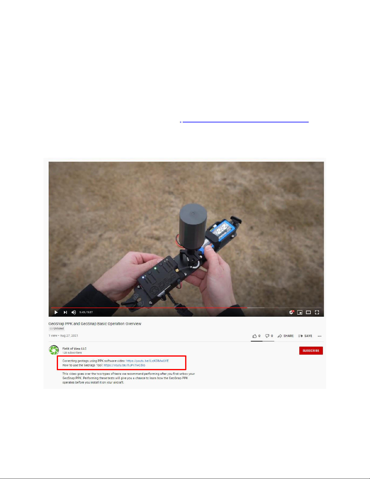
The fastest way to get a sense of how the GeoSnap Basic operates is to sequentially watch a series of YouTube
videos that Field of View has created.
Before operating the GeoSnap Basic for the first-time, be sure to watch:
Operation Overview: GeoSnap PPK and GeoSnap Basic https://www.youtube.com/watch?v=TpfOQX8rbSU
*this video was recorded using firmware 1.6.X, the firmware 1.12.X documented in this manual has slight variations
in the CONFIG file and Events File.
Note: Many of the videos have links in their description to additional videos that provide more details about
related topics.
Field of View GeoSnap Basic Manual 5
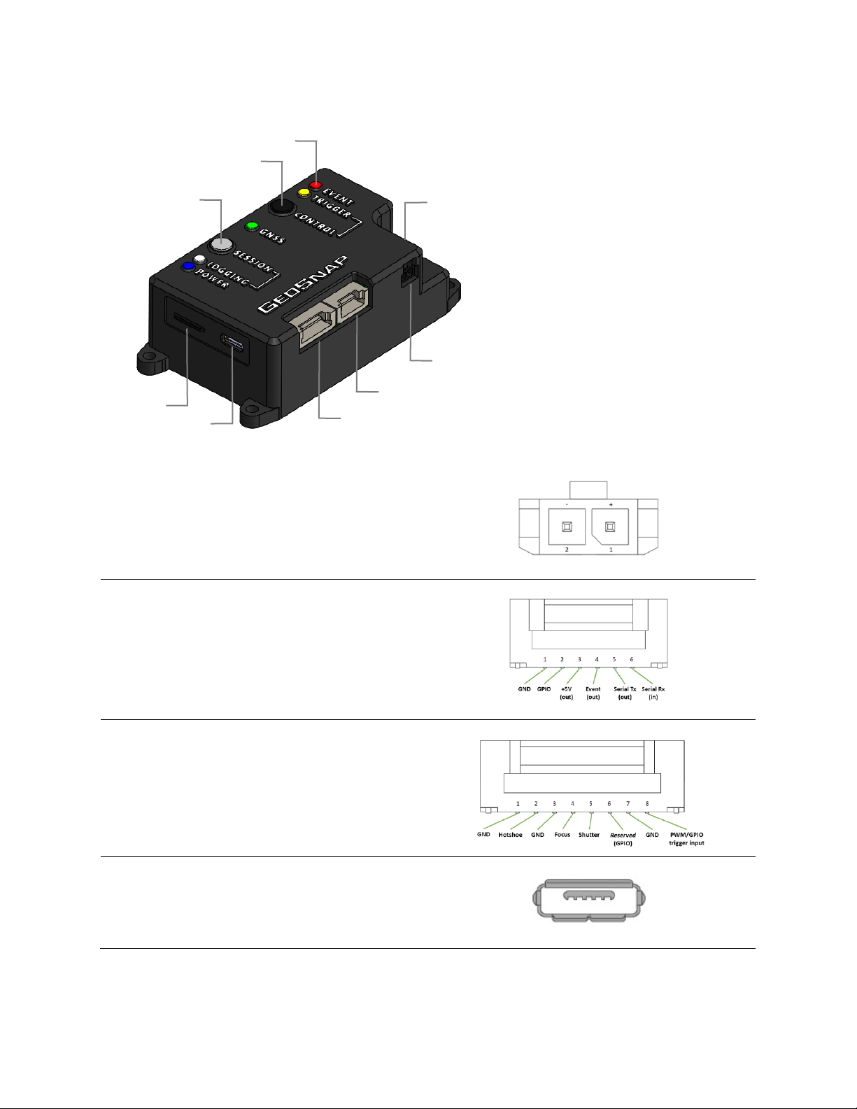
GEOSNAP INTERFACES
① Power connector
② Auxiliary (6-pin) connector
③ Camera (8-pin) connector
④ microUSB port
⑤ microSD card slot
⑥ Session button
⑦ Control button
⑧ LEDs
⑨ RF connector
Power connector
Voltage input range is 5.5V to 25V.
On-board connector: Molex 43650-0200
Mating connector: Molex 43645-0200
Auxiliary connector (6-pin)
Only used for MicaSense Rededge-MX and custom
integrations.
On-board connector: JST SM06B-ZESS-TB
Mating connector: JST ZER-06V-S
Camera connector (8-pin)
Camera hotshoe/trigger and PWM/GPIO interface
On-board connector: JST SM08B-ZESS-TB
Mating connector: JST ZER-08V-S
microUSB port
Used to connect the GeoSnap as a mass storage
device to a host Windows PC.
④
⑤
①
②
③
⑥
⑨
⑦
⑧

Field of View GeoSnap Basic Manual 6
microSD card slot
The microSD card is used to log events on-board the GeoSnap. The microSD card must be a 16 GB SanDisk Ultra
microSDHC UHS-1/Class 10 card. Spare microSD cards can be purchased directly from Amazon:
https://www.amazon.com/gp/product/B073K14CVB/ref=crt_ewc_title_dp_1?ie=UTF8&psc=1&smid=ATVPDKIKX0
DER
Session button
To safely end a logging session, press and hold the Session button (≈2 seconds) until the white, green, and red LEDs
turn solid. Once you have ended a session, you may start a new session by pressing the Session button once.
Control button
This button controls triggering according to the settings in the CONFIG file.
Retrieve System Information
To obtain information about the GeoSnap unit (carrier board serial number, firmware version, & bootloader
version), press and hold the Session and Control buttons while powering on the unit. Once the white, green, and
red LEDs turn solid, release the buttons and unplug power from the GeoSnap. Remove the microSD card, then use
a computer to read the system_info.txt file that was written to the microSD card’s root directory.
POWERING THE GEOSNAP SYSTEM
Battery Information
Two Turnigy 9XR 2200mAh 11.1V Li-Po batteries are included for powering the system. These batteries have built-
in undervoltage protection, which means that power will be cut from the output leads if any cell drops below 3.0V
(thus preventing damage to the battery). The advantage of using these batteries to power the GeoSnap (as
opposed to using power from the drone) is that the GeoSnap can keep logging and maintain GPS lock, even if the
drone’s batteries needs to be swapped when mapping large areas.
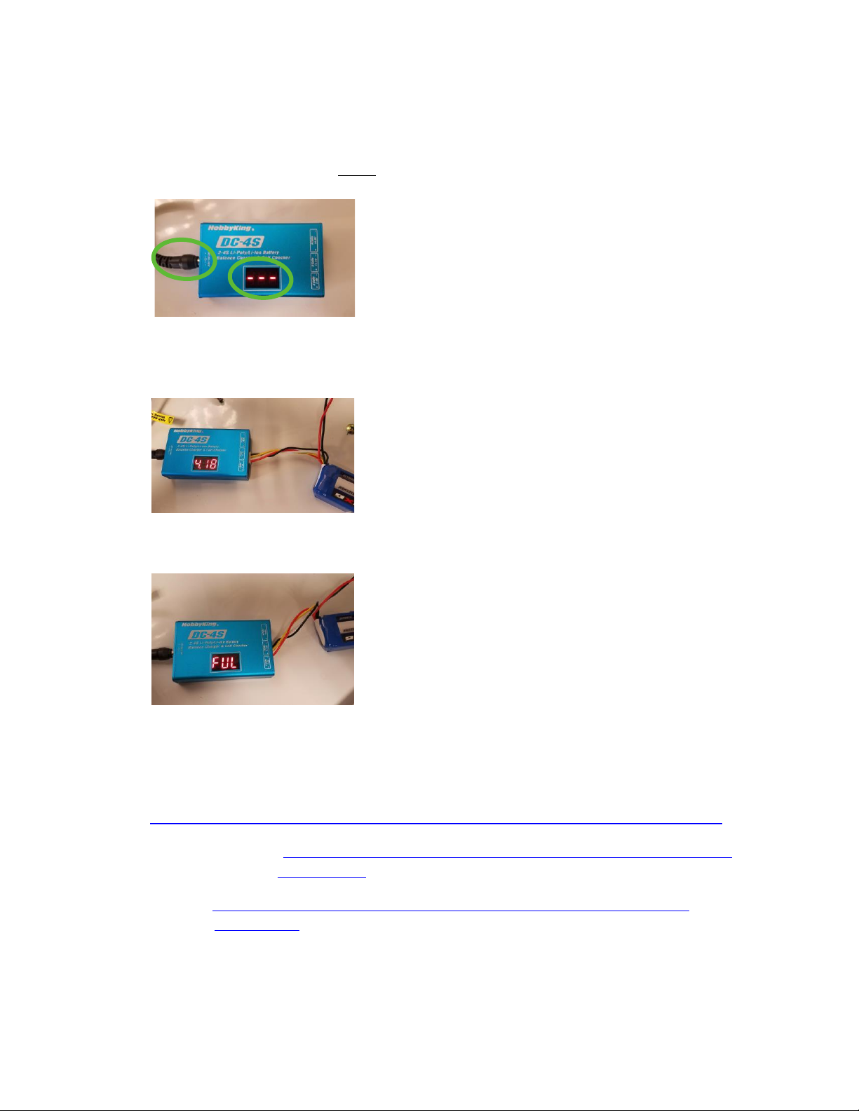
Checking Battery Voltage
You can check the voltage of the entire battery and it’s individual cells by plugging in the battery’s balance plug
into the connector labeled “3 Cells” on the included DC-4S charger/voltage checker (you can even do this while the
battery is powering the GeoSnap as depicted below).
A full battery has a total voltage of 12.6V –12.5V. The battery is practically depleted once it has reached 10V. A
fully charged battery can run the GeoSnap for about 8 hours.
Field of View GeoSnap Basic Manual 7
Battery Charging
1) Plug in the AC adapter into the wall.
2) Plug in the barrel power plug from the AC adapter into the DC-4S charger/voltage checker. Check to make
sure that 3 dashes are displayed before plugging in the battery (this indicates that there is indeed power
getting to the charger and that it isn’t just operating as a voltage checker).
3) Insert the balance plug of the battery into the connector labeled “3 Cells”. The charger will display the
overall voltage battery and the voltage of each cell as it charges. Charging a fully depleted battery takes
about 2 hours and 30 minutes.
4) Once the battery is fully charged, the charger will display “FUL” and begin to beep. At this point you
should disconnect the battery and unplug the AC adapter from the wall.
Purchasing Additional Batteries
Additional batteries, charger/voltage checkers, and AC adapters can be purchased directly via the links below:
Battery: https://hobbyking.com/en_us/turnigy-9xr-safety-protected-2200mah-3s-1-5c-transmitter-pack.html
DC-4S charger/voltage checker: https://hobbyking.com/en_us/hobbykingr-dc-4s-balance-charger-cell-checker-
30w-2s-4s.html
AC Power Adapter: https://hobbyking.com/en_us/power-supply-12v-3a-interchangeable-plug-adapter-
upgraded.html

Field of View GeoSnap Basic Manual 8
LEDS AND ERROR CODES
The GeoSnap Basic is equipped with five LEDs to communicate the status of the system. The behavior of each of
the LEDs is described in the tables below.
Operational codes
LED
Behavior
Description
Power (Blue)
Shines solid while the system is powered on
Logging (White)
Illuminates whenever the system writes data to
the microSD card.
GNSS (Green)
1 flash: searching for satellites
event FixStatus logged as: NO
2 flash: at least 1 satellite is being tracked
event FixStatus logged as: NO
3 flash: 3D fix with accuracy estimate over 3 m
event FixStatus logged as: 3D>3
Solid: 3D fix with accuracy estimate under 3 m
event FixStatus logged as: 3D
Trigger (Amber)
Flashes when a camera trigger command is sent
Event (Red)
Flashes when the system detects that an image
has been captured
Field of View GeoSnap Basic Manual 9
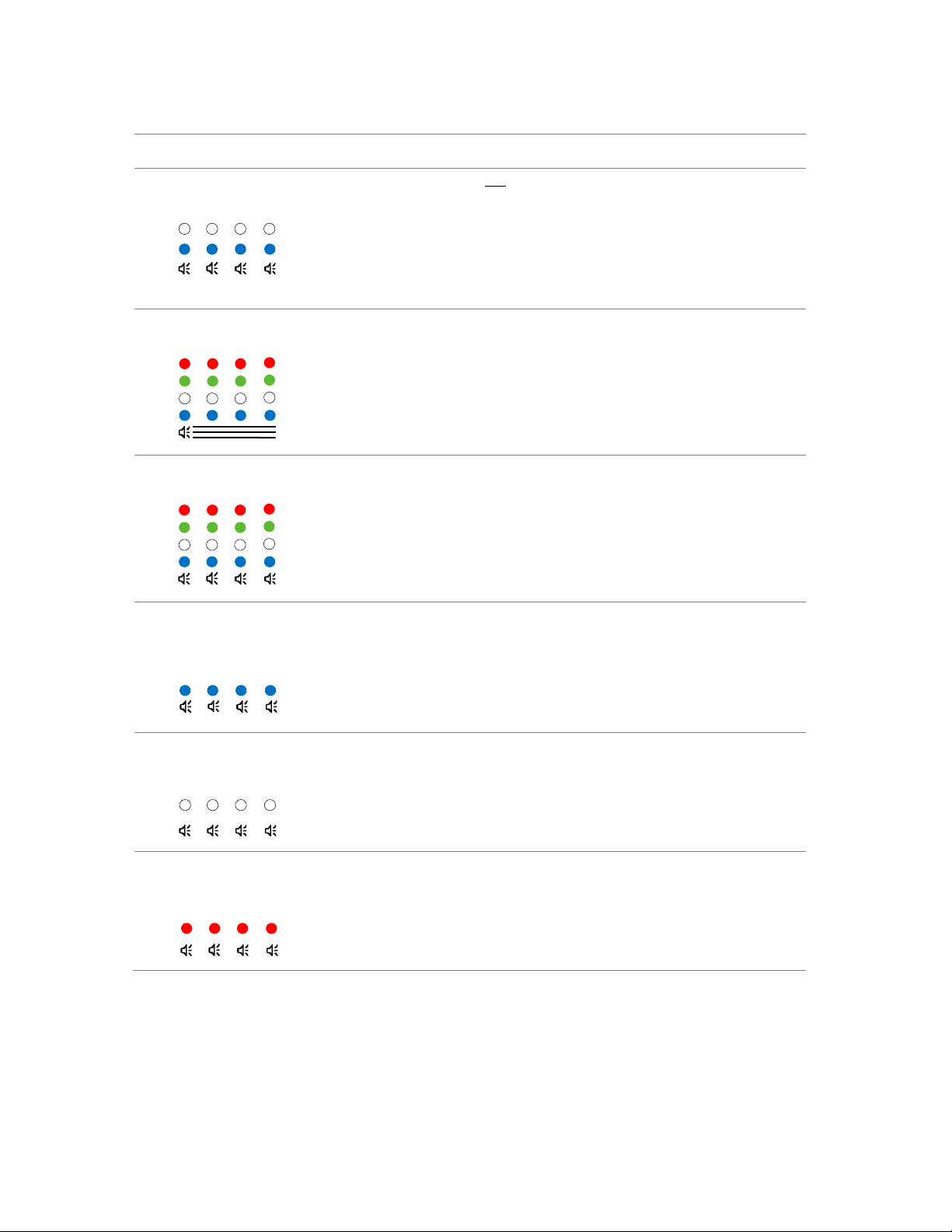
Error codes
LED Error Code
Description/Action
Flashing blue and white LEDs
(w/ speaker beep) for 10sec at boot
The user has not acknowledged that the settings in the
CONFIG file have been reviewed.
1. Open the CONFIG file and make sure that the settings
are correct for your mission
2. For the “Did you review the settings?” question at
the bottom of the CONFIG page, select “Yes, I have
reviewed these settings” in the dropdown menu.
Flashing blue, white, green, red LEDs
(w/ continuous speaker)
microSD card is not inserted.
1. Insert a microSD card into the system
Flashing blue, white, green, red LEDs
(w/ speaker beep)
There is a problem with the microSD card. It is not seated
properly, or it is corrupted.
1. Try re-seating the microSD card
2. Try re-formatting the microSD card using a computer
(check out section A-1 of the appendix for a guide on
how to do this)
Flashing blue LED
(w/ speaker beep)
Communication with the GNSS receiver was temporarily
interrupted.
1. System will continue to operate, but gaps in data may
be present
2. If this error code persists, contact Field of View.
Flashing white LED
(w/ speaker beep)
An error has occurred.
1. Check the microSD card and open the error_info.txt
file for more specific information about the error.
Flashing white LED
(w/ speaker beep)
There is a general error.
1. If this error code persists, contact Field of View.

Field of View GeoSnap Basic Manual 10
SYSTEM OPERATION
Required Equipment
Be sure to have a Windows laptop or desktop available with the ability to read a microSD card and with the Google
Chrome browser installed (necessary for viewing/editing the CONFIG.html file).
Image Number Reset
The GeoSnap does not get the actual image names from the camera. For each new session, the first event
recorded will always be labeled as event_00001. It is recommended to set the camera’s file numbering setting to
“Reset”(using the camera’s menu). Then, before starting a new GeoSnap logging session, clear all images off the
camera’s SD card. This will cause the first image taken to be named DSC00001.JPG (or something similar depending
on which camera you have). By having the image numbering and the event numbering both start at 1, it is easier to
quickly ensure that there is an event for each image captured after your flight.
Operation Procedure:
1. Make sure there is an appropriate microSD card in the GeoSnap and the CONFIG file settings are correct
for your mission (see the GeoSnap Basic Files section in the manual to learn more about the CONFIG file).
2. Plug in the power cable. The blue Power LED will illuminate and the white, green, and red LEDs will cycle
while the system is booting up.
3. After the system has booted, the green GNSS LED will start a single flash sequence indicating that the
system is searching for satellites.
4. If the Trigger Mode is set to “Time” and the Trigger Control is set to “Auto-start”, the first trigger
command will be sent as soon as the system has completed its boot up sequence.
5. If the GeoSnap Basic’s antenna has an unobstructed view of the sky, then the green GNSS LED should
begin to double flash in less than 30 seconds (indicating that it is tracking at least one satellite).
6. If the GeoSnap Basic’s antenna has an unobstructed view of the sky, then the green GNSS LED should
begin to triple flash within 1 minute (indicating that it is has a 3D fix).
7. If distance or overlap trigger modes are set to “Auto-start”, the first trigger command will automatically
be sent immediately after the estimated accuracy reaches 3 meters or less OR 1 minute after the system
first acquired a 3D fix (whichever comes first).
8. If the GeoSnap Basic’s antenna has an unobstructed view of the sky, you will observe the green GNSS LED
advance to shining solid within 1-2 minutes (indicating that it is has a 3D fix with accuracy estimate of 3
meters or less). This would typically be the time to start your flight. The estimated accuracy of the
GeoSnap Basic is 2-3 meters.
9. Once you are done with your session, safely stop logging by pressing and holding the white Session button
(≈2 seconds) until the white, green, and red LEDs turn solid. You may now take one of the following
actions:
a. Press the Session button when you are ready to start a new session. If the antenna maintained a
clear view of the sky, the GNSS status should be the same as when the previous session was
stopped.
b. Remove the microSD card and insert it into your computer to check the events log, copy session
folders to your computer, and/or change settings in the CONFIG file. When finished, safely eject
the microSD card from your computer and re-insert it into the GeoSnap (which is still powered
on). Press the Session button when you are ready to start a new session.
c. Connect the GeoSnap to a Windows PC using a microUSB cable. The GeoSnap will configure itself
as a mass storage device and act as a USB drive. You can check the events log, copy session
folders to your computer, and/or change settings in the CONFIG file. When finished, safely eject

Field of View GeoSnap Basic Manual 11
the USB drive from your computer. Press the Session button when you are ready to start a new
session.
d. Power down the GeoSnap and save a copy of the session folder(s) to your computer.
10. The events file contains the standard accuracy geotags and just needs to be associated to the images
using the Geotags Tool. Check out this video on how to use the Geotags tool. Once that quick step is
complete, the geotags are ready to be imported directly into a stitching software.
GEOSNAP BASIC FILES
FILE/FOLDER STRUCTURE
The GeoSnap Basic microSD card file/folder structure is outlined below:
•Configuration file (CONFIG.html)
•Session folder with valid GNSS data (yyyy-mm-dd_hhmmss)
oEvent file (yyyy-mm-dd_hhmmss.txt)
oCopy of the CONFIG file used for the session (yyyy-mm-dd_hhmmss_config_snapshot.html)
oGeotags application file (Geotags Tool v4.6.exe)
•Session folder without any valid GNSS data (1980-01-06_000001)
oEvent log (1980-01-06_000001.txt)
oCopy of the CONFIG file used for the session (1980-01-06_000001_config_snapshot.html)
oGeotags application file (Geotags Tool v4.6.exe)
CONFIGURATION FILE
The CONFIG file is an HTML file used to configure the settings of the GeoSnap Basic. Each time the GeoSnap boots
or starts a new session, it searches the root directory of the microSD card for the CONFIG file and reads the
settings. If a CONFIG file is not present, the GeoSnap will generate a default CONFIG file (in this case, the blue and
white LEDs will flash/beep for 10 seconds at boot-up letting you know that you should review/edit the settings).
It is highly recommended to open and save the CONFIG file using the Google Chrome web browser. Note that an
internet connection is not required to view and edit the CONFIG file. The interactive interface consists of a variety
of fields and drop-down menus that you can use to select your trigger mode, trigger parameters, and to record the
camera-to-antenna offset for your drone. Once you are done editing the settings, follow these instructions:
Saving Instructions:
1. Right click on an empty spot inside your browser window and select "Save as..."
2. Leave the file name as "CONFIG", but make sure the save as type is "Webpage, Complete"
3. Navigate to the root directory of your microSD card and then press "Save"
4. If there is already a CONFIG file present, a window will appear asking if you want to replace it. Press "Yes"
5. Safely eject the microSD card from your computer and proceed to operate the GeoSnap system
Field of View GeoSnap Basic Manual 12
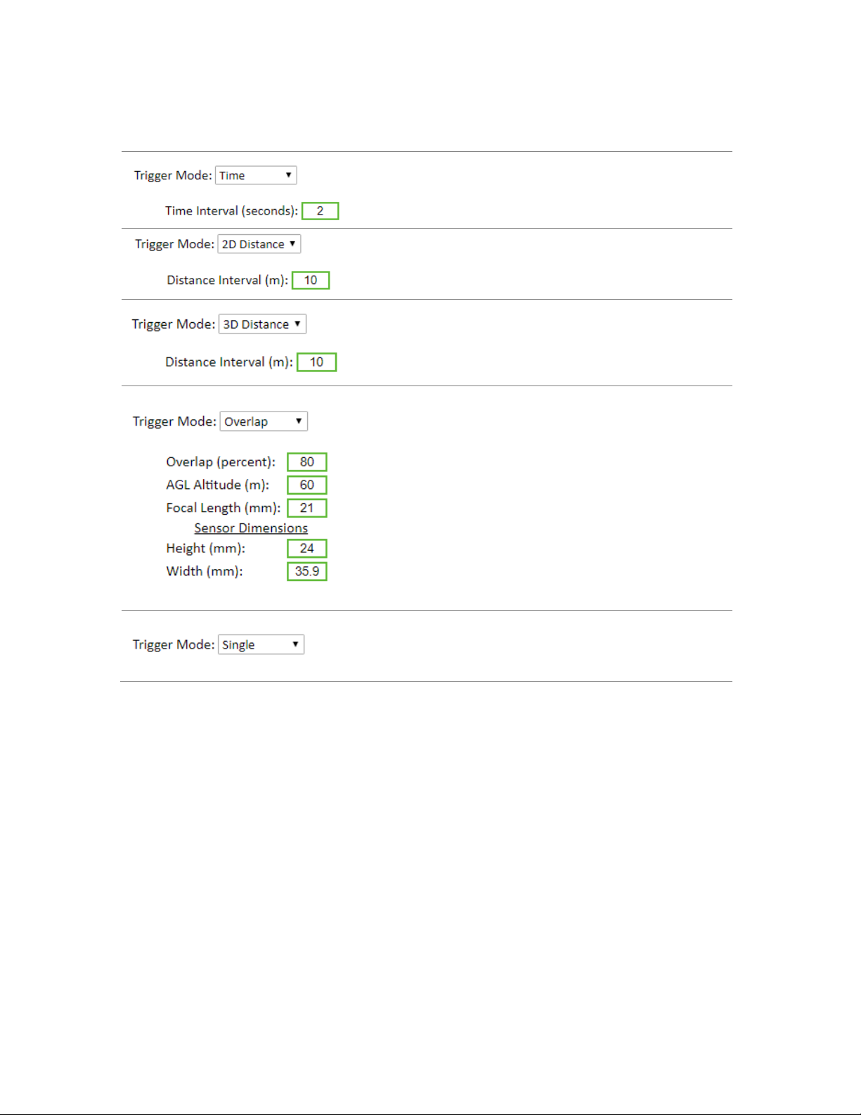
Trigger Mode
Trigger Mode
Description
Time mode sets the system to trigger on a set time interval in
seconds. Min value is 0.3 s, max value is 10,000 s.
[Default setting: 2 seconds]
2D Distance mode sets the system to trigger at a set
horizontal distance interval in meters. Min value is 0 m, max
value is 10,000 m.
[Default setting: 10 m]
3D Distance mode sets the system to trigger at a 3D distance
interval in meters (combined horizontal and
vertical distance traveled). Min value is 0 m, max value is
10,000 m.
[Default setting: 10 m]
Overlap mode sets the system to trigger at specific interval to
maintain a desired frontal overlap percentage between
images. This requires the input of various values including
the desired overlap percentage, the Above Ground Level
altitude the mission will be flown at, the focal length your
camera’s lens, and the camera sensor dimensions. Only the
Height value of the sensor dimension is used in the overlap
calculation since most cameras are mounted in the
“landscape” orientation relative to the direction of flight. If
your camera is mounted in the “portrait” orientation, then
simply type in larger dimension of the sensor in the Height
field.
[Default settings: Shown left]
Single mode sets the system to trigger one image per trigger
control input sent (see the next section).

Field of View GeoSnap Basic Manual 13
Trigger Control
Trigger Control
Description
Auto-start mode is available for Time, 2D
Distance, 3D Distance, and Overlap
triggering modes. When the Trigger Mode is
set to Time, the first trigger command will
be sent once the system is done booting.
When the Trigger Mode is set to 2D
Distance, 3D Distance, or Overlap, the first
trigger command will automatically be sent
immediately after the estimated accuracy
reaches 3 meters or less OR 1 minute after
the system first acquired a 3D fix
(whichever comes first).
Press and hold the Control button on the
GeoSnap to start triggering, an audible beep
will sound to confirm the triggering
sequence started. Press and hold the
Control button on the GeoSnap to stop
triggering, an audible double beep will
sound to confirm the triggering sequence
has been stopped.
A PWM input on the white wire of the
PWM/GPIO-input-cable can be used to
control triggering. Refer to the section titled
“PWM Behavior” for more information.
A GPIO signal on the white wire of the
PWM/GPIO-input-cable can be used to
control triggering. Refer to the section titled
“GPIO Behavior” for more information.

Field of View GeoSnap Basic Manual 14
PWM Behavior
By selecting PWM input in the Trigger Control field, a second drop down will appear called Behavior. This
dropdown allows you to specify which transitions (low-to-high, high-to-low etc.) will trigger the GeoSnap. The
GeoSnap will interpret any pulse widths shorter than 1700 microseconds as a “low”, and any pulse widths longer
than 1700 microseconds as a “high”.
Behavior
Description
If the GeoSnap is not triggering,
then a transition from a low pulse
width to a high pulse width will start
triggering. If the GeoSnap is already
triggering, then a transition from a
low pulse width to a high pulse
width will stop triggering.
If the GeoSnap is not triggering,
then a transition from a high pulse
width to a low pulse width will start
triggering. If the GeoSnap is already
triggering, then a transition from a
high pulse width to a low pulse
width will stop triggering.
The GeoSnap will trigger while the
pulse width remains high. As soon
as the pulse width goes low, the
GeoSnap will stop triggering.
The GeoSnap will trigger while the
pulse width remains low. As soon as
the pulse width goes high, the
GeoSnap will stop triggering.

Field of View GeoSnap Basic Manual 15
GPIO Behavior
By selecting GPIO input in the Trigger Control field, a second drop down will appear called Behavior. This
dropdown allows you to specify which transitions (rising edge, falling edge) will trigger the GeoSnap. A “low”GPIO
signal is defined as 0-1.0V whereas a “high” GPIO signal is defined as 2.3-5V. Rising edge refers to the transition
from a low GPIO signal to a high GPIO signal, whereas falling edge refers to the transition from a high GPIO signal
to a low GPIO signal. The signal must remain at high or low status for at least 50 milliseconds for the GeoSnap to
properly interpret the GPIO signal.
Behavior
Description
If the GeoSnap is not triggering, then
a transition from a low GPIO signal to
a high GPIO signal will start
triggering. If the GeoSnap is already
triggering, then a transition from a
low GPIO signal to a high GPIO signal
will stop triggering.
If the GeoSnap is not triggering, then
a transition from a high GPIO signal
to a low GPIO signal will start
triggering. If the GeoSnap is already
triggering, then a transition from a
high GPIO signal to a low GPIO signal
will stop triggering.
The GeoSnap will trigger while the
GPIO signal remains high. As soon as
the GPIO signal goes low, the
GeoSnap will stop triggering.
The GeoSnap will trigger while the
GPIO signal remains low. As soon as
the GPIO signal goes high, the
GeoSnap will stop triggering.
Field of View GeoSnap Basic Manual 16
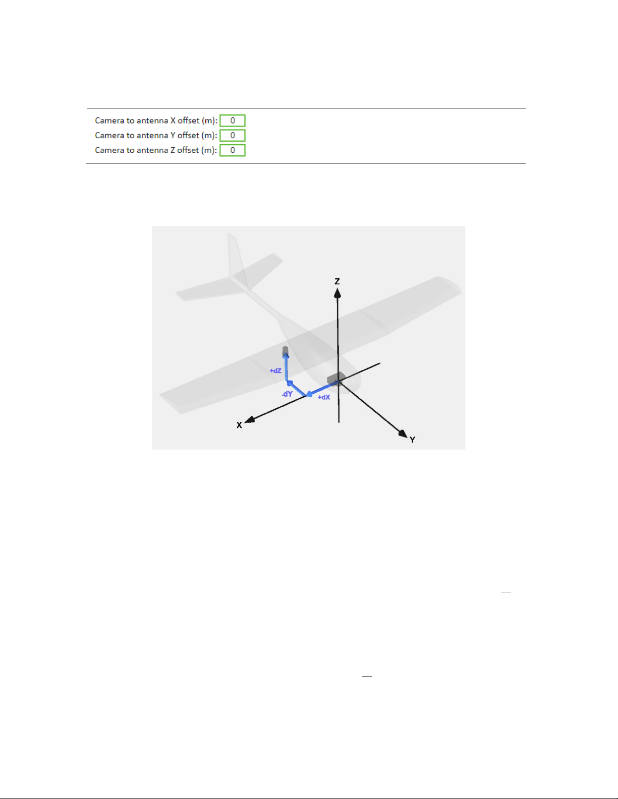
Offsets
Camera to Antenna Offsets
Description
Type in the X, Y, and Z offsets from the camera to the
antenna. More information on how to do this correctly is
below.
This diagram show how the X, Y, and Z axis aligned to an airframe. It also shows that an offset may be positive or
negative depending on where the antenna is mounted relative to the camera.
The simple, fast way to determine the offsets when using the GeoSnap is to follow these steps:
1) Use a tape measure or ruler to estimate the X and Y offset from the lens centerline to the center of the
antenna. A rough estimate (+/- 2cm) is sufficient since any error in the X and Y offset measurements tend
to get averaged to near 0 when performing grid mapping missions. Keep in mind that the all the offsets
need to be entered into the CONFIG file in meters.
2) The Z offset is more critical to measure accurately. Add the following distances to get the Z offset value
when using the GeoSnap
dZ = antenna L1 phase center-to-bottom of antenna + bottom of antenna-to-focal plane mark( o ) of the
camera + lens focal length
For the grey helical antenna that is included with most GeoSnap kits, the distance from the antenna L1
phase center to the bottom of the antenna is 0.0318 meters. The resulting equation would be:
dZ = 0.0318 meters + bottom of antenna-to-focal plane mark( o ) of the camera + lens focal length

Field of View GeoSnap Basic Manual 17
Settings Reviewed
Settings Reviewed
Description
If “Yes, I have reviewed these
settings” is selected, blue and white
LED will no longer beep for 10sec
after booting. The objective of this
feature is to help prevent the
situation where you accidently fly a
mission with the wrong settings.
[Default value: No]
EVENTS FILE
The yyyy-mm-dd_hhmmss.txt Events File is a comma delimited text file that contains a log of the uncorrected
position data and other GNSS information for each event. You can view the file contents by opening it with a text
editor, such as Notepad.
The first line in the events file displays parameters such as system serial numbers, firmware version, receiver
information, and the X, Y, and Z offset values that were entered in the CONFIG file.
The data fields contained in the events file are described below:
Item
Sample Value
Description
Event
event_00001
Event number. Starts at event_00001 every time a new session starts
on the GeoSnap and increments by 1 for each image captured.
Lat[deg]
46.904083939
Latitude in decimal degrees
Lon[deg]
-96.811011085
Longitude in decimal degrees
Alt[WGS84-m]
258.305
Altitude above the WGS84 ellipsoid, in meters.
Omega[deg]
0
Omega angle, in degrees. This column is necessary for a Pix4D
compatible log. The value will always be zero as this data isn’t available.
Phi[deg]
0
Phi angle, in degrees. This column is necessary for a Pix4D compatible
log. The value will always be zero as this data isn’t available.
Kappa[deg]
-315.22
Kappa angle, in degrees. This column is necessary for a Pix4D
compatible log. The Kappa is generated by multiplying the Course Over
Ground by -1.
LatAccy[m]
1.241
The GNSS receiver’s estimate of horizontal accuracy (at the antenna).
LonAccy[m]
1.241
The GNSS receiver’s estimate of horizontal accuracy (at the antenna).
AltAccy[m]
1.636
The GNSS receiver’s estimate of vertical accuracy (at the antenna).
GPSdate
2018-06-22
GPS date calculated from GPS week and time of week.
GPStime
17:20:55.391180
GPS time calculated from GPS week and time of week (this time is
different than UTC time because it does not take into account leap
seconds) http://leapsecond.com/java/gpsclock.htm
SystemT [s]
126.759
GeoSnap system time. The time since the GeoSnap has been powered
on.
GPSweek
2006
GPS week.

Field of View GeoSnap Basic Manual 18
GPStow[s]
494455.391180
GPS time of week, in seconds.
TDOP
0.529
Time dilution of precision
HDOP
0.621
Horizontal dilution of precision
VDOP
0.818
Vertical dilution of precision
Alt[MSL-m]
285.289
Altitude above standard sea level, in meters
COG[deg]
315.022
Course over ground, in degrees.
VHoriz[m/s]
00.013
Velocity horizontal, in meters/second.
Vup[m/s]
00.023
Velocity up, in meters/second.
T_Etime[s]
0.045
The amount of time in seconds elapsed between the GeoSnap sending
a trigger command and receiving capture confirmation back from the
camera.
AgeDiff[s]
6
Age of differential, in seconds.
FixStatus
3D>3
NO, 3D>3,3D, and UNKNOWN
SatsInView
23
Number of satellites that are directly in view of the antenna (note: this
number will typically be higher than the number found for SatsUsed)
SatsUsed
12
Number of satellites used to determine the coordinates found in the
events file
CONFIGURATION FILE SNAPSHOT
The yyyy-mm-dd_hhmmss_config_snapshot.html file is an HTML file that contains the parameters used for the
session. While the original CONFIG file is in the root directory and is used to change GeoSnap settings, the CONFIG
file snapshot cannot be changed and is found in every session folder that gets generated. Note that an internet
connection is not required to view the CONFIG file snapshot.
GEOTAGS TOOL
The Geotags Tool is a simple application that gets written to every session folder. It has three main functions:
1. It creates a Pix4D and Agisoft compatible “geotags file” using the position data from the events file and
the image name/numbering scheme you specify.
2. It creates a KML file that allows you to quickly see your geotags in 3D using Google Earth.
3. It can embed geotags and their accuracy estimates into the metadata (Exif and XMP) of your images.
The following are two different step-by-step guides on how to use the Geotags Tool. The first focuses on how to
create the geotags file and KML file only, while the second focuses on how to also embed coordinates into the
metadata of your images. A video of the process can also be found at
https://www.youtube.com/watch?v=I9JPxTwCBio.
Field of View GeoSnap Basic Manual 19
Generate an uncorrected Geotags File & KML File
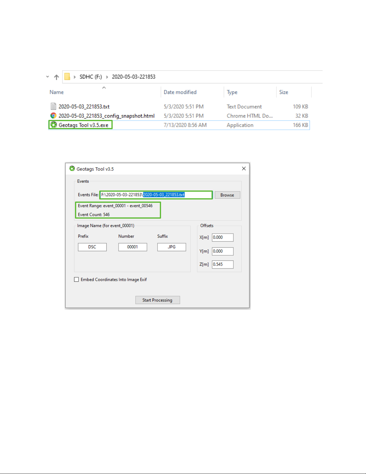
1. Launch the Geotags Tool by double clicking the Geotags Tool application in the session folder with your
mission data.
2. The application automatically finds the events file in the folder it was launched from and populates it in
the top bar (you also have the option to browse for a different events file). Upon finding a valid events
file, the application will display the Event Range and Event Count.
Field of View GeoSnap Basic Manual 20
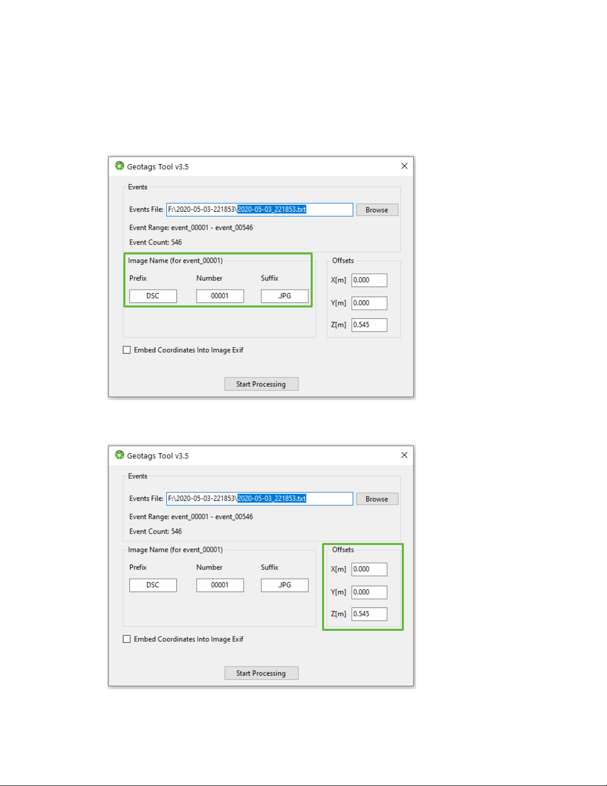
3. Use the Image Name pane to specify the image name/number that corresponds to event_00001. You can
manually edit the Prefix, Number, and Suffix fields or you can drag and drop the image file that
corresponds to event_00001 into this pane (the Geotags Tool will then automatically parse the Prefix,
Number, and Suffix). The fields are pre-populated for a Sony image named “DSC00001.JPG” to
demonstrate the parts of a file name that constitute the Prefix, Number, and Suffix. If you manually type-
in the image Number, be sure to include any neccessary leading zeros.
4. If the X, Y, and Z offsets are different than what got automatically imported from your events file, then
you can edit them in the Offsets pane.
This manual suits for next models
1
Table of contents
Popular Industrial Equipment manuals by other brands


LNS
LNS Express 332 S2 instruction manual

Siemens
Siemens RHVPS03 installation instructions

Harrington
Harrington NTH operating instructions

Motrona
Motrona SinCos SI220 operating manual

Minebea Intec
Minebea Intec PR 6246/12 installation manual

Maxcess
Maxcess Tidland Force5 Chuck Installation operation & maintenance


