Mark 7 Primer Xpress User manual

MARK 7® RELOADING PRIMER XPRESS USER MANUAL VERSION 1.1, COPYRIGHT
ALL RIGHTS RESERVED
1
Mark 7® Primer Xpress
Instruction Manual v 1.1
Read this manual. Understand all safety and operating instructions. Failure to comply
with the warnings and instructions may result in serious injury, illness, or death.

2
Primer Xpress Instruction Manual Version 1.1
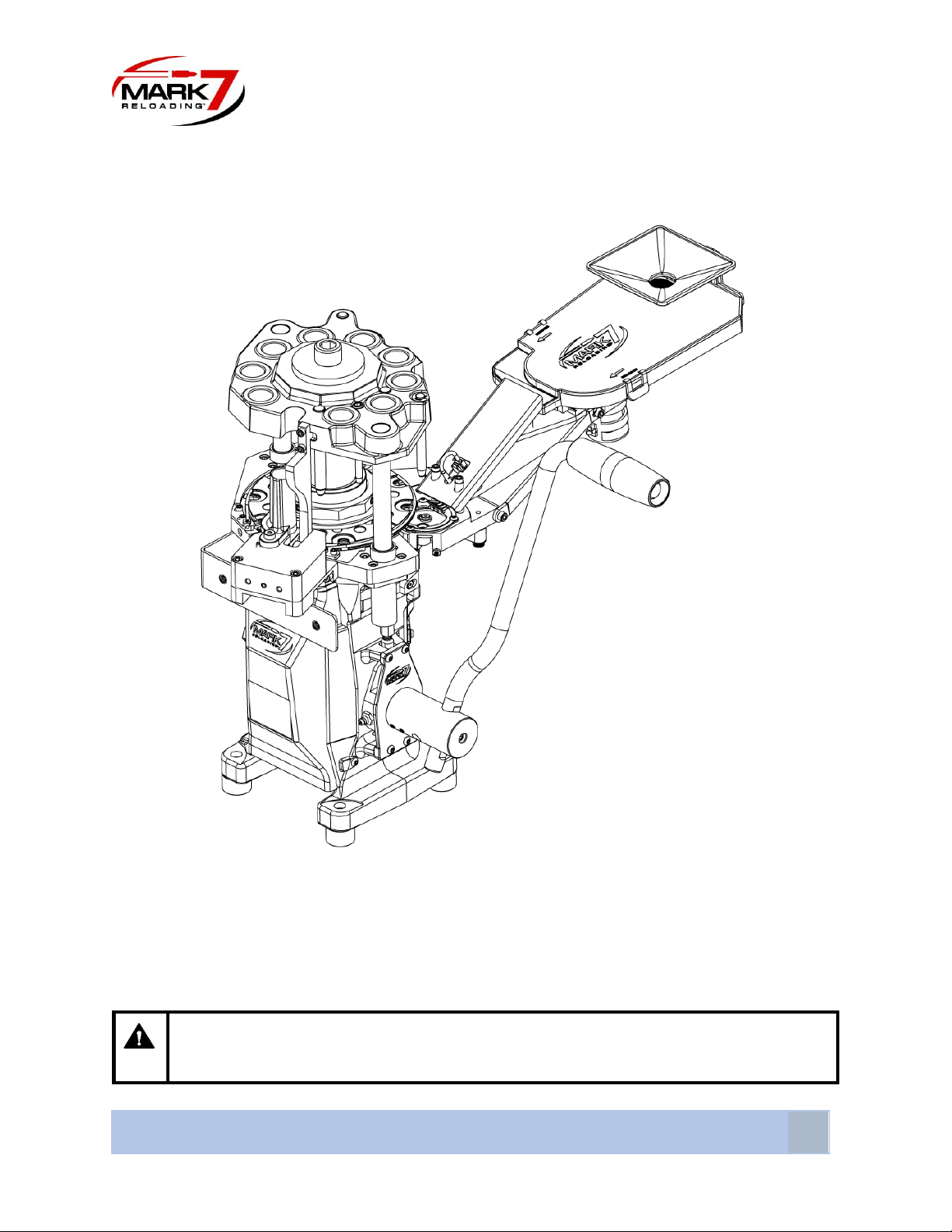
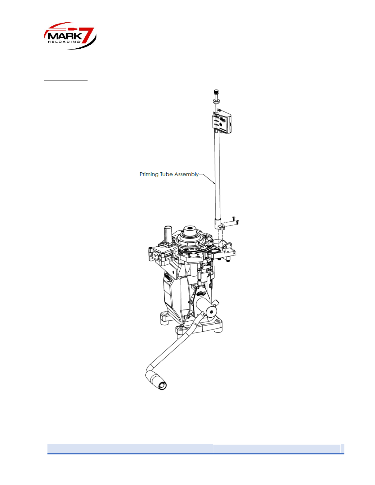
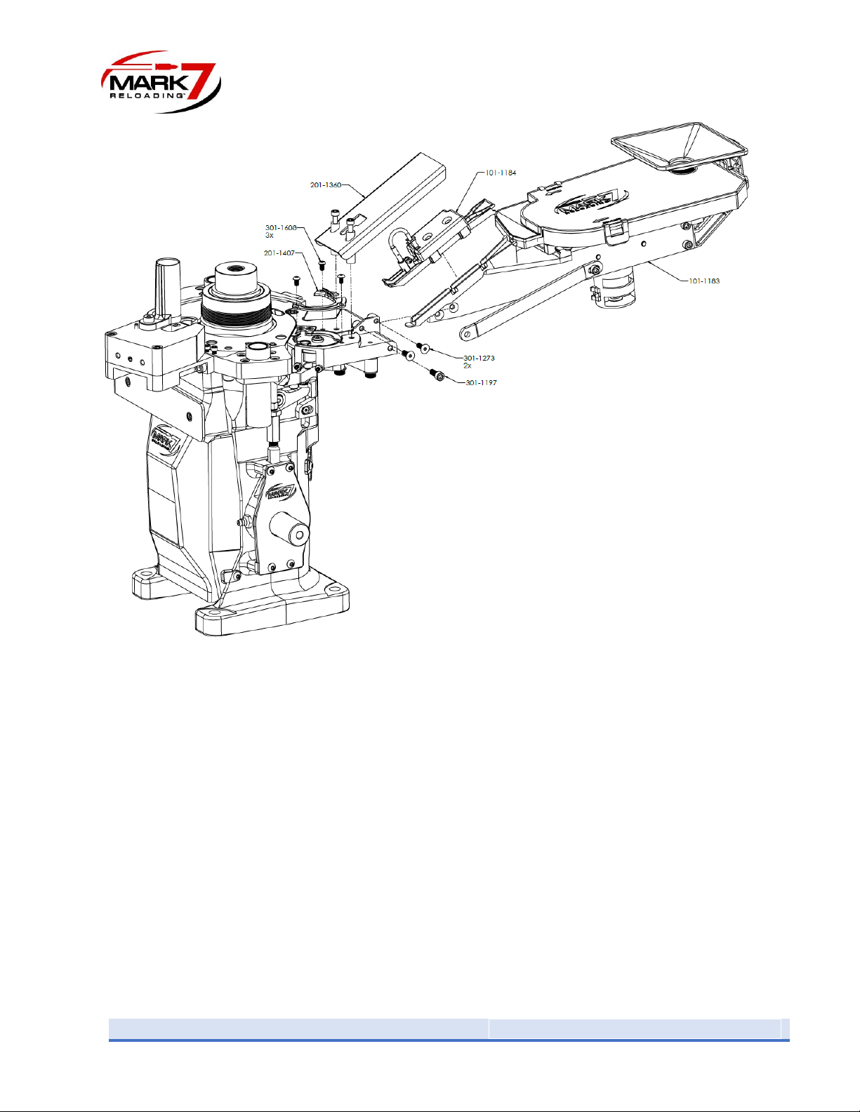
Mark 7’s Automated Primer Xpress is a totally new, patent pending technology which provides
nearly 100% successful primer orientation for your loading machine. This completely unique
design features an oscillating primer reservoir which effortlessly orients primers and allows
continuous primer feeding. No more stopping your machine to reload primers using clumsy
tubes! Simply add more primers into the built-in funnel without interruption to your loading
operation. The large hopper can hold 300+ primers and includes a tough polycarbonate safety
cover, which also keeps dust and debris out of the system. In the unlikely event that an up-side-
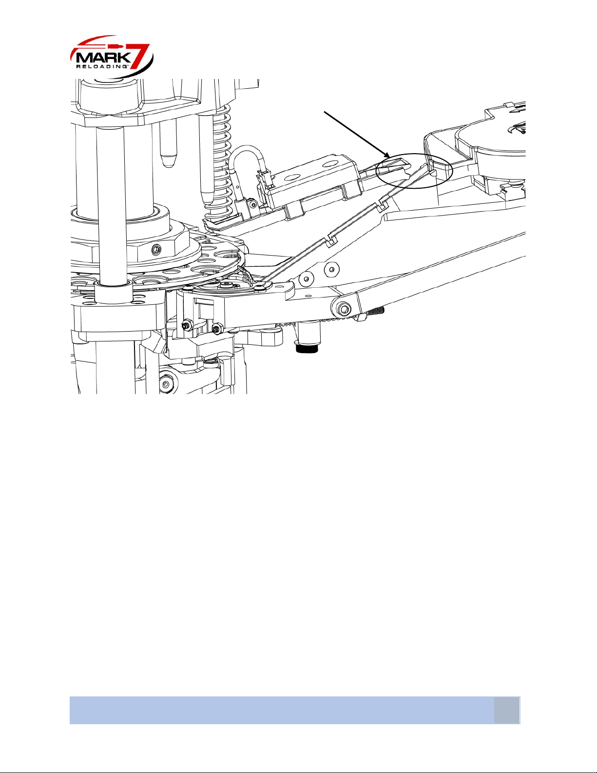
down primer does make it into the feed ramp, our failsafe sensor will detect it and sound an
alarm for manual presses and stop the operation on automated machines. In addition, change
over between small and large size primers is easy to do and all parts are included. Dual optical
sensors automatically start/stop the feed system to provide primers as needed. Primers are fed
into your machine using a simplified single slot feed disc mechanism for positive, reliable primer
positioning.
Warning!
•Primers are explosive and improper handling can lead to primer detonation and injury
to the user. Follow all safety guidelines when operating this devise.
•Always have the steel safety shield installed before operating this devise.
•Always wear safety glass when working with primers.
•Never force any primers. If a jam occurs, carefully remove excess primers, and gently
clear the jam.
•Primer dust can accumulate on the surfaces where primers travel. Periodically clean all
surfaces of the Primer Xpress with a clean, damp cloth.
•Never smoke when reloading or around primers and/or powder.
•Only store primers in their original packaging. If primers are left in the tray after loading,
remove them and return them to the original packaging.
•Always keep the cover on the primer hopper when operating the devise.
•Primer pockets should be clean and military cases must have the primer crimp removed
before seating primers.

MARK 7® RELOADING PRIMER XPRESS USER MANUAL VERSION 1.1, COPYRIGHT
ALL RIGHTS RESERVED
3
Two versions of the Primer Xpress are offered. One for the APEX-10 and one for Evolution
presses.
•Primer Xpress for APEX-10 includes fully assembled Primer Xpress unit with wiring
harness, control box, power adapter, dual I/O cable, steel safety shield and mounting
hardware.
•Primer Xpress for Evolution includes fully assembled Primer Xpress unit, shuttle disc
priming unit with large/small primer discs and punches, wiring harness, control box,
steel safety shield, power adapter, dual I/O cable, and mounting hardware.
Table of Contents
Table of Contents .........................................................................................................................................3
APEX-10 version Assembly.....................................................................................................................4-7
Evolution version Assembly…………….…….….....……...………………………………………..………………...……….….8-13
Primer Size Change………….……………………………………………………………………………………………………………14-15
Control Box Functions………………………………………………………………………………………………………………………..16
Operating the Primer Xpress…..…………………………………………………………………………………………..…………….17
Autodrive Setup………………………………………………………………………………………………………………………………..18
Setting the Upside-Down Primer Sensor….………………………………………………………………………………………..19
Troubleshooting……………………………………………………………………………………………….……………………………….20
Adjusting the Primer Disc Stops…….……………………………………………………………………………………………..20-21

4
Primer Xpress Instruction Manual Version 1.1
Assembly
APEX-10 Press
Figure 1. Priming Tube Assembly removal
1) Remove the priming tube assembly from the press by removing the two flat head
screws on the primer tube base.

MARK 7® RELOADING PRIMER XPRESS USER MANUAL VERSION 1.1, COPYRIGHT
ALL RIGHTS RESERVED
5
Figure 2. Primer Tube Assembly component removal
2) Remove plastic primer disc cover (201-1403) and loosen the shuttle disc retaining screw
(301-1602) several turns. Remove the plastic insert (201-1428) from the slot in the
shuttle housing. See Figure 2.

6
Primer Xpress Instruction Manual Version 1.1
Figure 3. Primer Xpress exploded view
3) Slide the Primer Xpress primer chute into the slot in the shuttle primer housing where
the insert (201-1428) was removed and under the shuttle disc. Make sure it is fully
seated in the slot. Attach the chassis (101-1183) to the shuttle housing using the
supplied mounting screws (301-1273). The two flat head screws are positioned into the
two chamfered holes and thread into the shuttle housing. The third hex head screw
(301-1197) passes through the stabilizing brace and into the shuttle housing. Apply
upwards pressure on the rear of the Primer Xpress chassis as the mounting screws are
tightened. See Figure 3.
4) Re-tighten the shuttle disc retaining screw (301-1602), then install the clear cover (201-
1407) over the shuttle disc.

MARK 7® RELOADING PRIMER XPRESS USER MANUAL VERSION 1.1, COPYRIGHT
ALL RIGHTS RESERVED
7
Figure 4. Primer Chute Cover installation
5) Install the primer chute cover with sensors (101-1184) onto the chute. Note that there
are two notches on the top of the cover which fit onto two lugs on the top of the chute.
Hold the cover at angle and slide the notches into the lugs, then push the cover down so
that it snaps into the latch on the shuttle disc cover. (When needing to remove the
cover, release the latch first and then lift the cover up and off the lugs.)
6) Attach the plugs from the wiring harness into the receptacles in the back of the control
box marked Motor and Sensors.
7) Plug the power adapter into the receptacle in the back of the control box marked
DC12V.

8
Primer Xpress Instruction Manual Version 1.1
Evolution Press
Note: The shuttle disc priming assembly has the small primer disc installed when received. If
you want to use large primers, first change the primer punch, primer punch bushing and the
shuttle disc following the instructions titled “Primer Size Change”.
Figure 5. Primer Xpress installed on an Evolution

MARK 7® RELOADING PRIMER XPRESS USER MANUAL VERSION 1.1, COPYRIGHT
ALL RIGHTS RESERVED
9
Removing Standard Priming System
1. Clear the Shell Plate and Priming System of components and detach Case
Feed Tube. Power off Autodrive (if installed) and move Tool head to down
position. Loosen and remove the Main Screw, Main Washer, Tool Head and
Spring (see below).
Main Washer
Tool Head
Main Screw
Spring
Case Feed Tube

10
Primer Xpress Instruction Manual Version 1.1
2. Loosen Eject Finger screws and swing the Eject Finger down. Loosen Retaining
Stations screws. Loosen 4X Shell Plate Nut screws and remove the Shell Plate Nut.
Remove Shell Plate and Retaining Spring.
3. Remove Front and Back covers, then remove Priming End Stop. Underneath the
Back cover remove the Shoulder Screw and underneath the Front cover slide out the
Primer Slide.
Shell Plate Nut
Shell Plate
Retaining Spring
Eject Finger
Retaining
Station
screws
Retaining Station screws
Shell Plate Nut screws X4
Eject Finger
screws
Eject Finger Screws
Back cover
Front cover
Shoulder Screw
Priming End Stop
Primer Slide

MARK 7® RELOADING PRIMER XPRESS USER MANUAL VERSION 1.1, COPYRIGHT
ALL RIGHTS RESERVED
11
4. Pull the Link Arm out until the Shoulder Screw is accessible, then remove the
Shoulder Screw. Remove the Top and Bottom Screws, then pull the Standard
Priming System up to remove it.
5. Place the Shuttle Disc Priming assembly onto the press frame and secure it using the
two supplied hex head screws (301-1125 & 301-1170). The 301-1125 will be installed
from below the press frame and 301-1170 will install from the top.
Link Arm
Bottom Screw
Shoulder Screw
Top Screw
Standard Priming System
Primer Punch
Spring. Primer Punch

12
Primer Xpress Instruction Manual Version 1.1
6. Attach the Link Arm of the press to the Pivot Arm on the bottom of the Shuttle Disc
Assembly using the shouldered hex head screw (301-1423) and washer (301-1647).
7. Loosen the Shuttle Disc by unscrewing the hex head screw in the center of the disc
and lifting the disc off the alignment pin, then remove the plastic insert (201-1428)
from the slot in the shuttle housing and put away.
8. Place the Primer Ramp in the slot in the shuttle primer housing where the insert was
removed. Make sure it is fully seated in the slot. Attach the chassis to the shuttle
housing using the supplied mounting screws (301-1273). The two flat head screws
are positioned into the two chamfered holes and thread into the shuttle housing.
The third hex head screw (301-1197) passes through the stabilizing brace and into
the shuttle housing. Apply upwards pressure on the back of the Primer Xpress
chassis as the mounting screws are tightened.
9. Tighten the Shuttle Disc back down.
10. Install the clear cover (201-1407) over the shuttle disc.
11. Install the Primer Ramp Cover (101-1184) onto the ramp.
Note: There are two notches on the top of the cover which fit onto two lugs on the top
of the chute. Hold the cover at angle and slide the notches into the lugs, then push the
cover down so that it snaps into the latch on the clear cover (201-1407). (When needing
to remove the cover, release the latch first and then lift the cover up and off the lugs.)
12. Install the Blast Shield (201-1360) over the Primer Ramp Cover using two hex head
screws (301-1707).
13. Attach the plugs from the wiring harness into the receptacles in the back of the
control box marked Motor and Sensors.
14. Plug the power adapter into the receptacle in the back of the control box marked
DC12V.
See Figure 6 on next page for visual guidance.

MARK 7® RELOADING PRIMER XPRESS USER MANUAL VERSION 1.1, COPYRIGHT
ALL RIGHTS RESERVED
13
Figure 6. Primer Xpress exploded view on Evolution

14
Primer Xpress Instruction Manual Version 1.1
Changing Primer Size
Figure 7. Priming assembly exploded view
1) Remove the 3 screws (301-1608) holding the Primer Disc Cover and remove the cover.
2) Remove the bolt (301-1602) in the center of the Primer Disc and lift off the disc.
3) Remove the 2 screws (301-1608) holding the primer guide plate (201-1425) and remove
it.
4) Remove the 2 screws (301-1125 & 301-1170) holding the body of the priming
mechanism to the press frame and the 1 bolt (301-1423) connecting the link arm from
the press to the primer mechanism. Be careful not to lose the bushing in the link arm.
TOP VIEW
Note: When reassembling,
it is critical to align the black
plastic guide as close to the
outside of disc as possible,
yet still allow the disc to
move freely.

MARK 7® RELOADING PRIMER XPRESS USER MANUAL VERSION 1.1, COPYRIGHT
ALL RIGHTS RESERVED
15
Figure 8. Primer Punch removal
5) Move the priming mechanism up and away from the press body and lift out the Primer
Punch as shown above.
6) Using a large, proper fitting, slotted screwdriver, unthread and remove the Primer
Bushing from the priming mechanism. Replace the punch with the provided desired size
punch and reassemble the unit in reverse order from above. Be sure to install the
correct size Primer Bushing and Primer Disc.

16
Primer Xpress Instruction Manual Version 1.1
Control Box Functions
Figure 9. Control Box faceplates
Power Switch: Located at the back of the control box, the switch turns the power On and Off.
Start/Auto Button: This button is pressed to turn on the oscillation unit and to set the unit to
run automatically.
Stop/Reset: This button is used to stop the action of the unit and to clear alarm signals.
Speed: This dial is used to control the oscillation speed of the unit.
Motor Override: This switch is used to override the sensors and allow the oscillation to
continue non-stop when the Start/Auto button is pressed. Oscillation will continue until the
Stop/Reset button is pressed. This feature is useful when a new batch of primers are added to
the hopper and you want to oscillate them down to fill the primer chute.
Alarm, PWR, Auto Lights: The alarm light will go on and a tone will sound when the primer
sensor detects an improperly oriented (anvil end facing down rather than up) primer. The alarm
is also triggered when out of primers. If the unit oscillates for approximately 15 seconds
without sensing a primer in the chute, the alarm will sound. Note: this is with the Motor
Override in the Off position.
The power light will be on when the power switch on the back of the unit is in the On position
and will go off when the switch is moved to the Off position. The auto light will be on when the
unit is running and the start and stop sensors are working.

MARK 7® RELOADING PRIMER XPRESS USER MANUAL VERSION 1.1, COPYRIGHT
ALL RIGHTS RESERVED
17
Operating the Primer Xpress
1) Add 100 to 300 primers by pouring them into the funnel over the hopper.
2) Set the Motor Override to On and press the Start/Auto button.
3) Move the Speed knob to a low setting and slowly increase the oscillation speed until
primers start to move along the guides inside the hopper and primers upset so that the
anvils are facing up.
Note: Different brand and different size primers will require their own speed settings. You
may need to experiment with the speed setting until the best results are obtained each
time primers are changed.
4) Once primers begin to enter the chute, press the Stop/Reset button. Then switch the
Motor Override to Off.
5) Press the Start/Auto button and the unit will run until primers reach the stop sensor.
6) Install the steel Safety Shield over the primer chute with the two provided screws. We
recommend that the shield always be in place when loading.
7) Press the Start/Auto and begin operating your press. Refill the hopper with primers as
needed while reloading.

18
Primer Xpress Instruction Manual Version 1.1
Autodrive Setup
Using the provided Dual I/O cable, plug one end into the Autodrive port on the Primer Xpress
control box and the other end into Port #1 on the Autodrive. See Figure 10. The Autodrive will
detect the Primer Xpress under PrimerSense. If either the upside-down primer sensor or the
low primer sensor trigger, the machine will stop and send a notification to the tablet. See Figure
11.
Figure 10. Side of Autodrive Console Inputs
Figure 11. PrimerSense Alarm Message

MARK 7® RELOADING PRIMER XPRESS USER MANUAL VERSION 1.1, COPYRIGHT
ALL RIGHTS RESERVED
19
Setting the Upside-Down Primer Sensor
Note: The Upside-Down Primer Sensor is factory set for generic small primers but be sure
to check sensor height is correct for your primers. Primer heights may vary between
manufacturers.
1) Fill the ramp with primers.
2) Loosen the screw behind the Upside-Down Primer Sensor and lift the sensor up so the
bottom of the sensor is about ½ halfway up the cylinder. See Figure 12.
Figure 12. Upside-Down Primer Sensor
3) Slowly push the Upside-Down Primer Sensor downwards until the alarm sounds. Press
the Stop/Reset button to silence the alarm, then carefully pull the sensor back upwards
slightly. There is a light on the sensor itself that will go on when it is too close to a
primer and go off when it is further away. This light will go off when you pull the sensor
up slightly. It is recommended that the sensor position be tested by placing a primer
into the chute oriented incorrectly (anvil down). The alarm should sound when
positioned over this primer but should not sound when over correctly oriented primers.
4) Tighten the screw behind the Upside-Down Primer Sensor once the sensor is properly
positioned.
Note: Large and small primers will need different settings for the sensor height. Sometimes
even different brand primers of the same size may require sensor adjustment.
Adjust height
Loosen

20
Primer Xpress Instruction Manual Version 1.1
Troubleshooting
•The Primer Xpress should be level side to side. If not level, adjust the press feet to
correct this.
•If primers settle on one side of the hopper and do not move down the guides, the press
feet may need to be lowered slightly on the opposite side of where the primers settle.
•If the shuttle disc binds after installing the Primer Xpress, make sure that the tab at the
end of the primer chute is fully seated into the slot under the shuttle disc.
•If primers are repeatedly flipping over (correct orientation to incorrect orientation) in
the hopper, the speed setting is too high.
•If primers travel down the hopper too slowly, the rear press feet may need to be raised
to increase the hopper angle.
•If primers are having difficulty being picked up by the Primer Disc, follow the steps in
Adjusting the Primer Disc Stops.
Adjusting the Primer Disc Stops
oFind the set screw (201-1398-01) and spring plunger (201-1499) underneath the
housing. Note: Assembly does not need to be removed from the press.
Figure 13. Primer Disc Stop Screws
oSet the set screw (201-1398-01) so that the Primer Slot is centered at the bottom of the
Primer Ramp.
Other manuals for Primer Xpress
1
Table of contents
Other Mark 7 Industrial Equipment manuals
Popular Industrial Equipment manuals by other brands

Samoa
Samoa 439100 Technical service guide

Hayward
Hayward Aqua Rite installation manual

schmersal
schmersal AZM201Z-I2-ST2-T-1P2PW-A Operating & assembly instructions

Richter
Richter SCK Series Installation and operating manual

Virutex
Virutex eb25 operating instructions

Tsubaki
Tsubaki Backstop BS-F Series manual