Harrington NTH User manual

EFFECTIVE: FEBRUARY1,1990
,_/
PRODUCTINFORMATION
for
:.. HARRINGTON
NAVY
TROLLEY HOIST
1,2,3,5TONCAPACllY
MODEL:NTH
~
"
CONTENTS:
1.Op~ratingandMaintenanceInstructions
2.PartsUst
3.ChainingInstructions
4.InspectionStandards
5.Disassembling&AssemblingInstructions
6. Trouble Shooting' ,<'
HARRINGTONHOISTS
HARRINGTON
HARRINGTONC~ES
""
Ii1\RRINGTONHOISTS,INC~ '"'~" ,,",
401 WEST END~AVENUE '><;-. .': '>"
MANHEtM,PA"'~7545 ' ,'".,~.,
r;, ':l' iP.HONE: (717) 6~gOOO "
.,-..J ,TOll FREE:'1-8OD-233-3010
.._.'-:..,:':;-~:-F-AX:.(717) 665-2861 '
;;: '0 "!'-o'
OperatingInstructions
Peerless NTH
ManualChainHoist
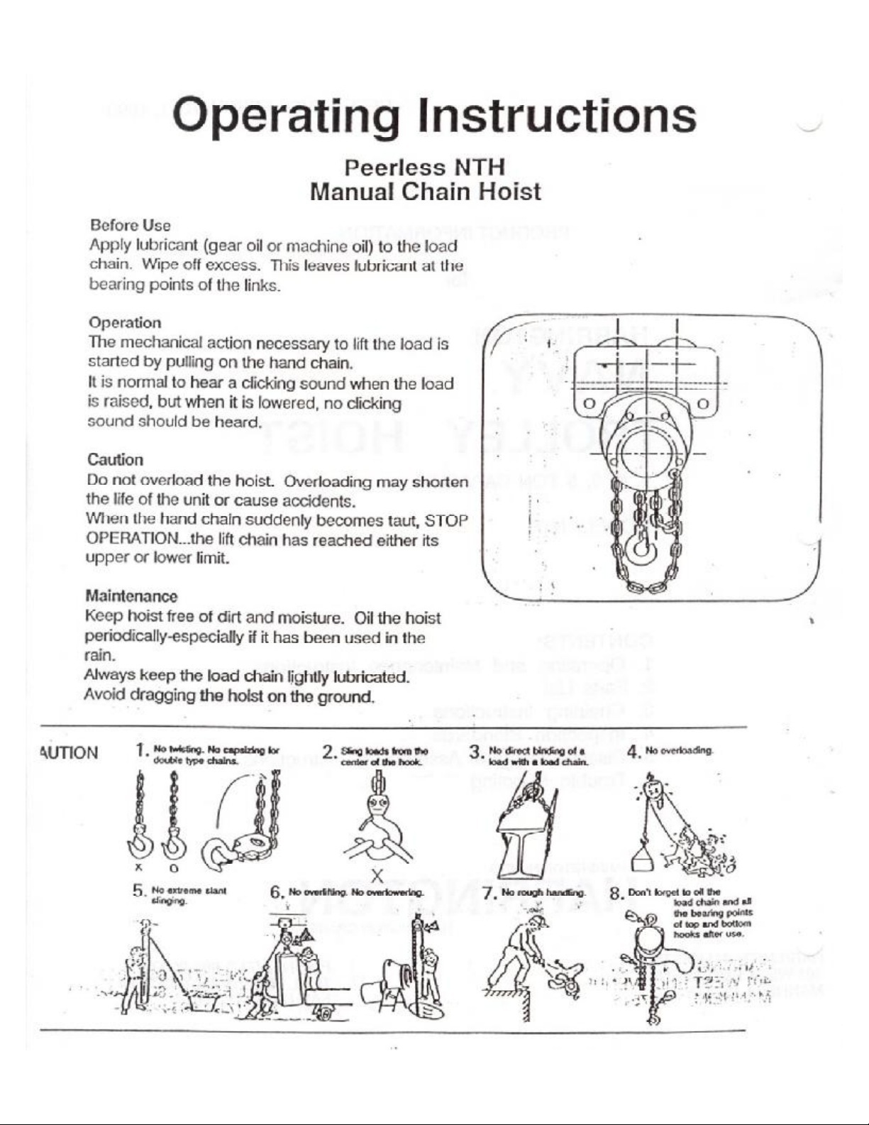
BeforeUse
Applylubricant(gearoilormachineoil)totheload
chain.Wipeoffexcess. Thisleaveslubricantatthe
bearingpointsofthelinks.
Operation
Themechanicalactionnecessarytolifttheloadis
startedbypullingonthehandchain.
Itisnormaltohearaclickingsoundwhentheload
israised,butwhenitislowered,noclicking
soundshouldbeheard.
Caution
Donotoverloadthehoist.Overloadingmayshorten
thelifeoftheunitorcauseaccidents.
Whenthehandchainsuddenlybecomestaut,STOP
OPERATION...theliftchainhasreachedeitherits
upperorlowerlimit.
Maintenance
Keephoistfreeofdirtandmoisture.Oilthehoist
periodically-especiallyifithasbeenusedinthe
rain. --
AJways-keeptheloadchainIjghtlylubricated.
Avoiddraggingthehoistontheground.
~
~
.- I I
y- t, [--i--I~+-
-:1---
i
0
:\
"
a.UTlON 4.Nooverloading.
1'. NotM6ting. Nocapsizing tor
doubIlI type chains. 2-Slingloadsfromthe
.center of.the hook.
(~
x0X
6. Nooverlifting.No0Yert0WerIng.
~
5Noextreme &!ant
.slinging.
~
3No .directbtridingofa
.load with . load chain.
8Don'tforgetto011the
.loadchainandaD
~R. thebearingpoints
~"\:-, oftopandbottom
hooksafteruse.
/

,~Operating Instructions
Peerless Manual andGeared Trolley
BeforeUse
Thepeerlessmanualtrolleycanbeadjustedinincrementsof1/8"bysimplyin~ertingor
removingadjustingspacerstofitavarietyofbeamflanges.Noadditionalspacersarerequired.
Toadjusttrolley(Fig.1): '
1.Removethestoppinsandslideoffsideplate8andspacersfromthesuspensionshafts.
2.Reinserttheappropriatenumberofinnerspacers for thedesiredflangewidth(Table1).
3.Insertsideplate"8"andexternalspacersandlockintoplacewiththestoppins.
~Installation
Foreasyinstallationthetrolleymaybeputontothe1-8eamflangefromtheopenendofthe
beam.StoppersshouldbeinstalledonbothendsoftheI-beamto.preventthetrolleyfrom
runningoffthebeam.
Ifthetrolleycannotbeinstalledfromtheopenendofthebeamthen:
1)Disconnectsideplate8fromtrolley.Leavehoistattachedtothesuspender (See1above).
CAUTION:Sincehoistandcomponentsareveryheavy,getassistancetoliftandholdhoist
andtrolleypartsinplace.
2)Check for propernumberofspacers. Useequalnumberofspacersoneachsideof
suspendersothatthehoistiscenteredbetweentrolleywheels.Ufthoistontobeam.
(SeeAg.1)
~3) Reinstallsideplate8andremainingspacers. Installstoppins.
4)Checktoseethathoistandtrolleyissecureonbeam.Allpinsareinplaceandkeepersplit
pinsareinstalled. -
5)Movetrolley.Itshouldmovefreely.Ititistootightorloose,adjustasrequiredbygoing
backtoStep1above.
Operation
Moveanunloadedtrolleybypullingontheloadchainofthehoist.
Movealoadedtrolleybypushingthesuspended load.
PrecautionsToBeTakenInOperation
1)Avoidslantpullingofchain.
Itisdangeroustopullthechainslant,withthetrolleyconnectedtothehoist,asthe
trolleyistiltedtoomuchandgivestoomuchstraintothebeam.
-2)Donotlet~etrolleybumpagainststopperatbear1.1orothE7trolleyonthesamebeam.
c. TakesuffiC1entcarenottoletthetrolleybumpagainstastopperattheendofthebeam
orothertrolleyonthesamebeam,asthiswillcausedamagetothetrolleysandthe
beamstopper.: ''L. -
3)Donotletthe'nandchaincatchaload.
Italoadiscaughtbythehandchainasitislowered,theloadedhandchainmaycause
damagetotheside-plate. '
4)Nev~rrT19yetrolleybypullingonthehoisthandchain.
.,i'J
.i~
_
"fl
_/il lihi
.'i' :" ,
.:>~~\iwr~' ..." .~'-
!'IJIalnteQ~_Q~:::' i :;IIJ .".
lubrIcationonthetrolleywheelsisrequired.Theyhaveshielded,pre-:lubricatedballbe~nngs.
~s_i~nally applyoilthroughthesmallholeinthepinionsupportonthegearedtrolley(FIg.3).
,'-.-,nt/,r'J '. \~
.->
--.".r-, --,"-1'" --{',-

Fig 1
a/@)
ñ
×ÒÒÛÎßÜÖËÍÌ×ÒÙÍÐßÝÛÎÍ ñù
ÞÑÔÌÚÑÎÍËÍÐÛÒÍ×ÑÒÍØßÚÌÑËÌÛÎ
ÊñÍÔÑÌÌÛÜÒËÌßÒÜÍÐÔ×ÌóÐ×Ò ,--;
-----
-.J
~
@
_Ol@)
SPLIT PIN
~(.
7
ÍØßÚÌÍÌÑÐÐÛÎÐ×Ò
ßÜÖËÍÌ×ÒÙÍÐßÝÛÎÍù
Table 1
NumberofAdjustingSpacers -"~.. ..J
,,'
--'--~~- ----- !-
lote;) Ì¿µ»ù²ø÷¬»¬¸»²«³¾¢®±²-°¿½»®-±º·²²»®-·¼»¿-
æ±´´·±©-:-.~' ,.' - -
~ample 1+:2
,ILNumber ±² Side Plate ß
Number ±²Í·¼»Ð´¿¬» B
011
Hole
A
BA-B= 1/S"
/
:.i y
Trotley
WMef -
Hand'
-""'-In,;., :°,"".. . "
-:> ..,,":~,.)i(.:,<..:,.I'
C::App.3/S"
.-.,,~ -~-
Fig.3 0.' .
"" ,.'
,-c'-,--',. Í«-°»²¼»®
".': ':° Fig.2
."\" ..:. '.-~'.
"
.,-,...-
-331/4 3'5/8 37/8 41/8 45/8 551/8 51/4 51/2 55/8 ?3(4 661/4 63/8 61/2 7
,WJdth 33/8 .,4
:aD-" ;
1Inner 3+3 4+4 5+5 6+6 7+7 9+9 ---, - - -- - - - -
Outer 12 10 8 6 4 0>
- - - - - - - - - - -
11/2Irtner ---1+1 1+2 4+4 5+6 6+6 6+7 7+8 8+8 8+9 9+9 - - - '--
2Outer ---16 15 10 7 6 5-: 3 2 1 0 - - ,- -
3Inrier ,_., --, 1+1 1+24+4 5+6 6+6 6+7 7+8 8+8 8+99+9 ---
Outer - - -16 15 10 ,7 ,,:6 -.5- '"3," '--:2 -1 0-- - -
5Inner - - - - - - 0+1 1+1 1+2 2-t:3 3+3 4+3 5+46+56+6 7+6 :9+8
Outer -----.- 16 ,15 14 12 11 10 8 654'.0

PARTSLIST
"ol-'n:1'"' I
\qq~i~p'-one assemblytorSTononly.
~t'~(M.o_~l~oJY --0 --- --" ,-- _0-----"--
,..
;',;.' ,:: ,\:
-- .. --, , --- !_-,~,--;
," =p-;' ':,
.""""""'" ok ,-
,-
No. Capacity
Fig. per
No. PartName Hoist 1 2 3 5
.
1SuspenderAssembly 1 50604 ëðêîî 50679 50725
3TopPin 1 CF163010 CF163015
4BottomHookCompleteSet 1M3021A010
16 SafetyLeverAssembly 1 CF071010
7 ChainPin 1 M3041010
8 SlottedNut 1M204901 0
9SplitPin 19009411 .
0BodyA 1CF101010 CF101015
1BodyB 1CF102010 CF102015
2 NamePlate 1 CF800010 CF800020 CF800030 CF800050
3 Frame 1CF1 05010 CF105015
1CF111010 CF111015 CF111050
14 Pinion 1**CF4111010 **CF4111015 fk*CF411105
5BallBearingA(Ag.14 1 9000103
6BallBearingB(Fig.14 1 9000201 9000202 9000300
BallBearingC(FiQ.14 1 9000105 9000106
'riA BallBearingD(Ag.14) 1 9000105 9000106
18 LoadSheave' 1CF116010 CF116015 CF116A050*
19 LoadGear 1CF114010 CF114015 CF116A050*
20 ChainGuide 1CF178010 CF178015
21 Stripper 1 CF162010 CF162015
22 SocketBolttor Body 29091284 9091285
?2A SocketBatttor Body 2 9091282 9091283
:>3 UNut for Body' 49098506
:>4 PawlPin 1CF156005
:>5 UNut for Fig.24 1 9098506
:>6 PawlSpring 1CF158005
7Pawl,:," 1.' CF155005
8SnapRingfor Ag.24 1 9047108
1 CF153010
29, fnctionDisc 1 **M3153020
0.FrictipnPlateB 1CF151010 ,-
,;/"" 1CF152010 - ' "-",, '
31 'RatchetDisc 1 ,CF4152010 ",'" "
,--"..' , '-,
311 8.4f.shirtfffofHatchet Disc 1M3.154020 ' i}:.]:':;i.cY_I,
.' --
-
Other Harrington Industrial Equipment manuals


