Fike SITA200plus User manual

26-0540 Issue 5
Sita200plus Repeater Panel V4.14
Repeater Panel
Installation Instructions
(TO BE RETAINED BY THE COMMISSIONING ENGINEER)

Sita200plus Repeater Panel Installation Instructions
2
Fike’s policy is one of continual improvement and the right to change a specification at any time without notice is reserved. Whilst every care has been
taken to ensure that the contents of this document are correct at time of publication, Fike shall be under no liability whatsoever in respect of such
contents.
Due to the complexity and inherent importance of a life risk type system then training on this equipment is essential, and commissioning should only be
carried out by competent persons.
Fike cannot guarantee the operation of any equipment unless all documented instructions are complied with, without variation.
E&OE.
Fike equipment is protected by one or more of the following patent no’s: GB2426367, GB2370670, EP1158472, PT1035528T, GB2346758,
EP0917121, GB2329056, EP0980056, GB2325018, GB2305284, EP1174835, EP0856828, GB2327752, GB2313690

Sita200plus Repeater Panel Installation Instructions
3
Contents
Introduction . . . . . . . . 4
System Design . . . . . . . 4
Equipment Guarantee . . . . . . 4
Anti Static Handling Guidelines . . . . . . 4
Warning . . . . . . 4
EMC . . . . . . 4
Repeater Panel . .
. . . . . .
5
Mounting the Repeater Panel . . . . . . 5
General Assembly . . . . . . . 5
Physical Dimensions .. . . . . . . 6
Power Supply Unit . . . . . . . 6
Topology and Cabling . . . . . . . 7
System Wiring Schematic . . . . . . . 7
Repeater Panel Connections . . . . . . 8
Terminals and Fuses . . . . . . . 8
General Operation . . . . . . . . 12
Repeater Panel Front . . . . . . . 12
Soft Key Menus . . . . . . . . 12
Access Codes . . . . . . . . 13
Access Levels . . . . . . . . 13
Access Level 1 (Normal) . . . . . . 13
Access Level 2 (User) . . . . . . . 14
Access Level 3 (Engineer) . . . . . . 15
Installation & Commissioning . . . . . . 16
Installation 1
st
Stage . . . . . . . 16
Installation 2
nd
Stage . . . . . . . 16
Commissioning . . . . . . . . 16
Fault Finding . . . . . . . . 17
Technical Data . . . . . . . . 18
Repeater Panel . . . . . . . 18
Technical Support . . . . . . . 18
Further Information . . . . . . . . 19
Battery Calculations . . . . . . . 19
Installation Checklist . . . . . . . 20
Commissioning Checklist . . . . . . 21
Cable Continuity and Insulation Test Results . . . . 22
Important Points . . . . . . . 24 – BACK PAGE

Sita200plus Repeater Panel Installation Instructions
4
Introduction
This Manual is intended as a guide to the engineering and commissioning principles of the Sita200plus
Addressable Intelligent Fire Alarm and Detection system, and covers the system hardware information only.
Due to the complexity and inherent importance of a system covering a ‘Life Protection Risk’, training on this
equipment is essential. Installation and commissioning should only be carried out by competent and approved
persons. For further details of the availability of commissioning services contact your supplier.
System Design
This document does not cover Fire Alarm system design, and a basic understanding is assumed.
A knowledge of BS5839: Pt 1: 2002 +A2: 2008 : Fire Detection and Alarm Systems for Buildings
is essential.
It is strongly recommended that a suitably qualified and competent person is consulted in connection
with the Fire Alarm System design and that the entire system is commissioned in accordance with the
current national standards and specifications.
Equipment Guarantee
The equipment carries no warranty unless the system is installed, commissioned and serviced in
accordance with this manual and the relevant standards by a suitably qualified and competent person
or organisation
Anti Static Handling Guidelines
Immediately prior to handling any PCBs or other static sensitive devices, it is essential to ensure that
a personal connection to earth is made with an anti-static wrist-strap or similar apparatus.
Always handle PCBs by their sides and avoid touching any components. PCBs should also be stored
in a clean dry place, which is free from vibration, dust and excessive heat, and protected from
mechanical damage.
Warning
Do not attempt to install this equipment until you have fully read and understood this manual.
Failure to do so may result in damage to the equipment and could invalidate the warranty.
Technical support will not be available if the instruction manual has not been read and understood.
Please have this instruction manual available whenever you call for technical support.
For further technical support please contact your distributor. Do not call the Fike Safety Technology
support department unless your distributor has first given their advice and attempted to rectify the
issue.
EMC
This equipment when installed is subject to the EMC directive 2004/108/EC. It is also subject to UK
Statutory Instrument 2006 No. 3418.
To maintain EMC compliance this system must be installed as defined within this manual. Any
deviation from this renders the installer liable for any EMC problems that may occur either to the
equipment or to any other equipment affected by the installation.
!
!
!
!
!
Sita200plus Repeater Panel Installation Instructions
5
Repeater Panel
Mounting the Repeater Panel
Firstly identify the proposed location for the repeater panel. Ensure that the repeater panel will be easily
accessible, and that account is taken of any subsequent work that may affect access.
The repeater panel should be mounted on a flat, vertical wall at a height where the indicators may be seen without
difficulty.
Like all electronic equipment, the repeater panel may be affected by extreme environmental conditions. The
position selected for its installation should therefore be clean and dry, not subjected to high levels of vibration or
shock and at least 2 metres away from any pager or radio transmitting equipment. Ambient temperatures should
be within the range given within the Technical Data section, i.e., not directly over a radiator or heater.
In common with all microprocessor-controlled panels, the repeater panel may operate erratically or may be
damaged if subjected to lightning induced transients. Proper earth/ground connections will greatly reduce
susceptibility to this problem.
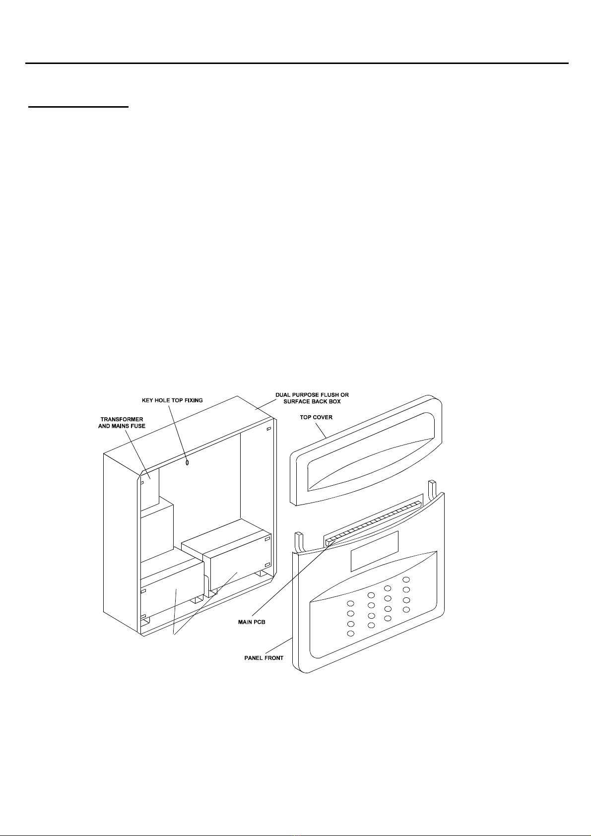
General Assembly
2 x 12V 3.2AH SLA
Yuasa NP3.2-12
Sita200plus Repeater Panel Installation Instructions
6
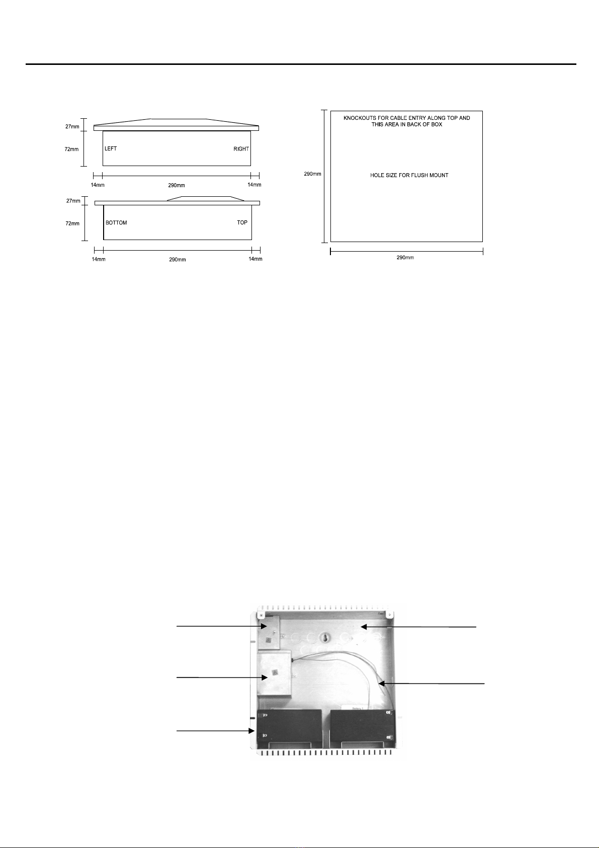
Physical Dimensions
The repeater panel back box is designed as a dual-purpose surface or flush unit. The 14mm flange facilitates
flush mounting. To allow installation of the main front moulding, this flange must be flush with the mounting
surface and not recessed into it.
Power Supply Unit
The repeater panel 230VAC supply requires fixed wiring between 0.75mm
2
and 2.5mm
2
, a 3 Amp fused un-
switched spur with local isolation, to be terminated into the fused terminals provided in the top left hand corner of
the back box and suitably differentiated from the low voltage cables in the repeater panel. The metal cover, held in
place with a locking nut, protects these terminals. The mains supply should be dedicated to the Fire Alarm system
and should be clearly labelled ‘FIRE ALARM: DO NOT SWITCH OFF’ at all isolation points.
The standby requirements are for 2 x 12v 3.2 Ah sealed lead acid batteries to be installed. These are to be sited in
the repeater panel back box in the provided enclosure along the bottom edge, with the terminals facing forward
and outwards (to left/right respectively). This is important to ensure that the battery terminals do not put any
pressure on the main PCB, which could happen if the terminals were bent out at an angle. The batteries should be
connected in series using the connection leads supplied. See the section entitled Repeater Panel Connections for
panel connections.
Note that batteries are electrically live at all times and great care should be taken to ensure that the terminals are
never presented with a short circuit. Care should be taken at all times, especially during transit, installation and
normal use.
Batteries no longer required should be disposed of in a safe and environmentally friendly manner by the battery
manufacturer or a suitable recycling service. They should never be incinerated or placed in normal rubbish
collection facilities.
Incoming mains supply
fuse housing
Transformer housing
2 x 12V 3.2 Ah Sealed
Lead Acid batteries
Knockouts at top
and rear
AC connection
cables
Sita200plus Repeater Panel Installation Instructions
7
Topology & Cabling
All system wiring should be installed to comply with BS 5839: Pt1: 2002 and BS 7671 (wiring regulations) and any
other standards relevant to the area or type of installation. A cable complying with the BS 5839: Pt1: 2002 (cables
required to operate for prolonged periods during fire conditions) is required. This must be a 2-core 1.5mm
2
screened fire resistant cable (ie. MICC, FP200, Firetuff, Firecell, Lifeline or equivalent).
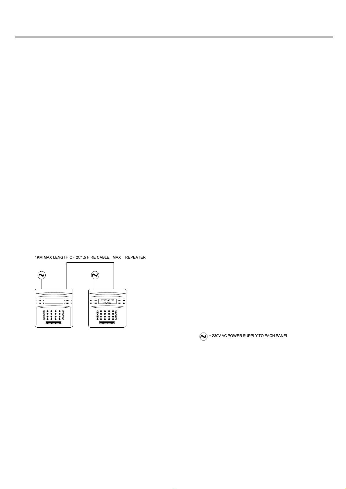
The Repeater Panel R-Bus connection must be installed as a radial circuit (daisy chain format) with a maximum
length of up to 1 km. A maximum of 1 repeater panel may be connected.
In order to protect against possible data corruption it is important ensure the following points are adhered to:
1. The cable screen between the panel and repeater must be connected to earth/ground at one
end only using the terminals provided. Ensure the end that is not connected is safely terminated in a
connector block to avoid unwanted shorting to any other point.
2. The cable screen must not be connected to earth/ground at any point other than the relevant
control/repeater panel, ie, do not connect the screen to a back box.
3. Do not use a 4-core cable as a data feed & return due to the possibility of data corruption. It is
essential that two 2-core cables are used if this is required.
Refer to the following System Wiring Schematic for further details.
System Wiring Schematic
1
CONTROL
PANEL
CONTROL PANEL MUST BE V4.14 OR LATER
Sita200plus Repeater Panel Installation Instructions
8
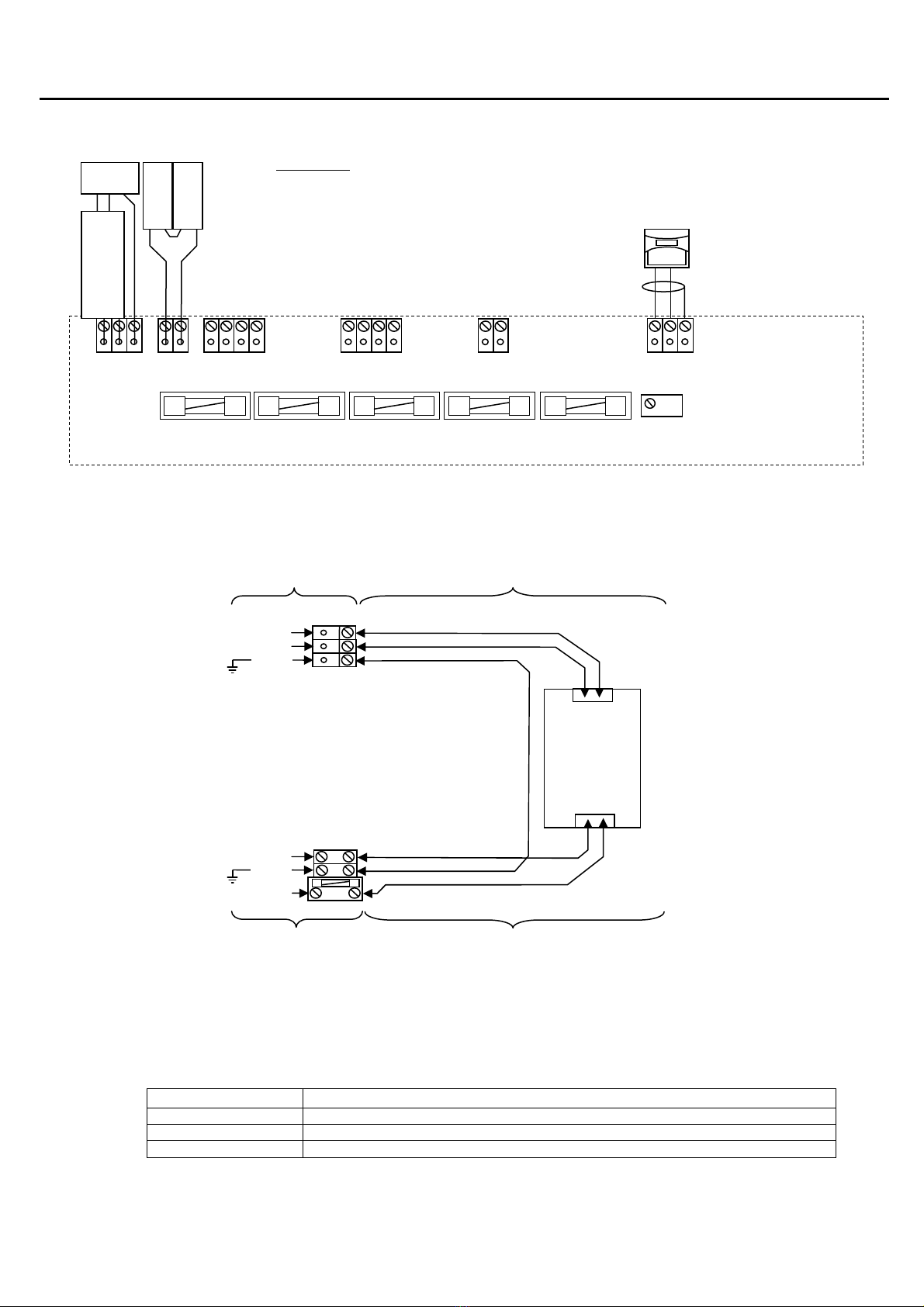
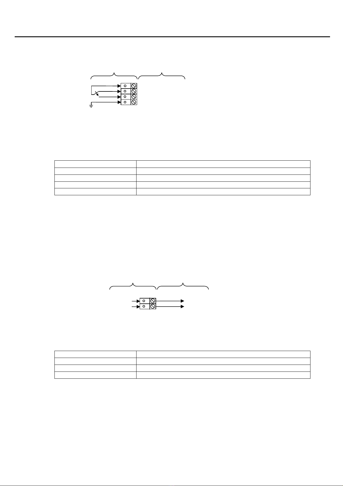
Repeater Panel Connections
Repeater Panel Terminals and Fuses
Power In – PSU+, PSU--, EARTH
The DC input to the main PCB is connected to the red and black leads coming from the switch mode power
supply mounted within the back box, and is the primary power supply for the system. This input is protected by the
3AT fuse labelled ‘F4 3AT POWER’.
Note: Control panels up to V4.11 do not use a switch mode power supply, but instead utilise a 230V AC to 40V
AC transformer, with yellow wires connecting to terminals marked TA and TB.
Terminal Description
PSU+ Power Supply Low Voltage DC +ve: 32V DC In
PSU- Power Supply Low Voltage DC –ve: 0V DC In
EARTH Mains Supply Earth
+ -- E
POWER IN
+ --
BATTERY 24V
C NC NO SPR
RELAY 1
C NC NO SPR
RELAY 2
+24V 0V
AUX PWR
+ -- SCRN
PC / RPT LINK
REPEATER PANEL
PCB
LCD CONTRAST
VR1
F4 3AT POWER F3 3AT BATTERY F5 200mAF AUX PWR F2 200mAF OUTPUT4 F1 200mAF OUTPUT5
230V AC
L N E
SWITC MODE PSU
MOUNTED IN BACK
BAT 1
+
-
BAT 2
+
-
REPEATER LINK:
MAX 1KM OF 2-CORE 1.5MM2 SCREENED CABLE
BETWEEN CONTROL PANEL AND REPEATER..
CONNECT EAC SCREEN TO EART AT ONE END
ONLY.
MAX 1 REPEATER PANEL.
CONTROL PANEL MUST BE VERSION 4.14 OR
LATER.
PSU --
PSU +
MAIN PCB SWITC MODE POWER SUPPLY
EART
RED
SCREEN
EART
BLACK
SWITC MODE
POWER SUPPLY
MOUNTED IN
BACK BOX
-- +
32V DC
230V AC
N L
EART
BLUE
BROWN
EART
LIVE
NEUTRAL
230V AC SUPPLY SWITC MODE POWER SUPPLY
….....
….....
….....
….....

Sita200plus Repeater Panel Installation Instructions
9
Mains Input: L, N, E
The 230V AC input is to be connected into the mains supply connection terminals provided in the back box. This
input is protected by a 3.15AT fuse.
Terminal Description
L Main Supply Live 230V AC Live
E Mains Supply Earth
N Mains Supply Neutral 230V AC Neutral
Battery Connections – BAT+, BAT-
The battery terminals require 24v from 2 x 12V 3.2Ah sealed lead acid batteries, connected in series, in order to
provide secondary backup power when the primary power fails. This input is protected by the 3A fuse labelled ‘F3
3AT BATTERY’.
Note that the charging circuit will be in its high impedance state (approximately 3V DC) if no batteries, faulty
batteries or only one battery is connected. The full 27V DC charging voltage should be present if the correct
batteries are connected.
If the system shows a charger or battery fault on first power up, leave the system to charge its batteries for 5-6
hours.
In order to test for correct operation of the batteries, remove the mains 230V AC fuse and allow the batteries to
settle from their charging voltage for approximately 5 minutes. The battery voltage should then be measured using
an electronic test meter and a voltage in the region of 27V DC should be seen.
Note that batteries are electrically live at all times and great care should be taken to ensure that the terminals are
never presented with a short circuit. Care should be taken at all times, especially during transit, installation and
normal use.
Batteries no longer required should be disposed of in a safe and environmentally friendly manner by the battery
manufacturer or a suitable recycling service. They should never be incinerated or placed in normal rubbish
collection facilities.
Terminal Description
BAT + Battery positive: 24V DC +ve
BAT - Battery negative: 0V
BAT --
BAT +
MAIN PCB BATTERIES
RED
BLACK
-- +
12V BATTERY
-- +
12V BATTERY
BACK BOX TO SWITC MODE POWER SUPPLY
EART
BLUE
BROWN
EART
LIVE
NEUTRAL
Sita200plus Repeater Panel Installation Instructions
10
Relay 1 – COM1, NC1, NO1, SPR1
Relay 1 consists of a ‘volt-free’ ‘change-over’ relay contact which is not fault monitored. The relay contacts are
rated at 30vDC / 2A max. The following options may be selected using Sita OSP:
1. Not configured (relay will not operate).
2. Common fire output (relay energised in fire).
3. Fire alarm signal output, monitored by input 1 (MI1+, MI1-) (relay energised in fire).
Terminal Description
COM1 Common contact
NC1 Normally closed contact
NO1 Normally open contact
SPR1 Spare terminal for general use. Not connected internally.
Relay 2 – COM2, NC2, NO2, SPR2
Relay 2 is not used in the Repeater Panel.
Auxiliary Power: +24V, 0V
An auxiliary 24V DC constant power supply is available if required. In order to protect battery standby and alarm
times, this output is limited to 200mA with the fuse labelled ‘F5 200mAF AUX PWR’. Additional remote Power
Supply Units should be installed to provide power for any additional load.
Terminal Description
+24V Aux power positive connection
0V Aux Power 0V connection
SCRN Field cable screen connection
COMMON
NORMALLY OPEN
NORMALLY CLOSED
SPARE
MAIN PCB FIELD CONNECTIONS
OV
+24V
MAIN PCB FIELD CONNECTIONS
24V DC LOAD

Sita200plus Repeater Panel Installation Instructions
11
Fuses
The fuses are located below the control panel terminals.
Label Description Fuse
F1 Output 5 F200mA
F2 Output 4 F200mA
F3 Battery T3A
F4 DC Input Power T3A
F5 Auxiliary 24V Power F200mA
LCD Contrast
The LCD contrast may be adjusted by rotating the screw on the variable resistor located adjacent to the fuses.
This may require many (10 to 20) rotations if the contrast is particularly out of adjustment.
LCD CONTRAST
VR1
Rotate anticlockwise
to reduce the
contrast (lighten text)
Rotate clockwise to
increase the contrast
(darken text)
Sita200plus Repeater Panel Installation Instructions
12
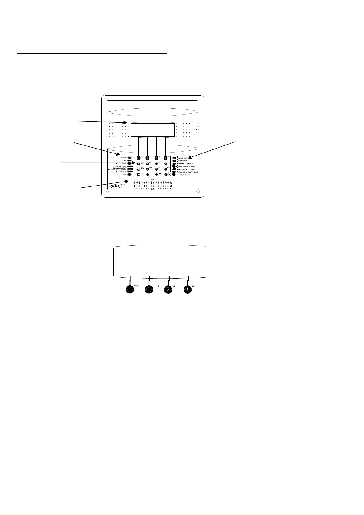
General Operation of Repeater Panel
Repeater Panel Front
LCD display
System status Fault & delay status
Keypad
Detection-Zone
Fire Indication
Soft Key Menus
For ease of use, a context driven menu system is used to control access to the system. Soft keys (software
allocation of button function) are used to pilot around the menu system, automatically prompting you with the
relevant options for your Access Level and system status.
The lower line of the display is arranged in the following format:
[DISPLAYon] [testDISP] [AL2 CODE] [->nextMENU]
Each section (eg., ‘[AL2 CODE]’) represents the function of the button immediately below on the keypad.
The high voltages and frequencies that are required to give a low current consumption for the LCD backlight may
cause the display to emit a slight humming tone whilst it is on. This is merely a feature of the technology required
in the system and will cease when the backlight switches off.
ADDRESSABLE FIRE ALARM 4V14
PROGRESSIVE FIRE SYSTEMS LTD
FOR SERVICE CALL 01234 567890
[DISPLAYon][testDISPLAY][AL2 CODE][nextMENU]
ADDRESSABLE FIRE ALARM 4V14
PROGRESSIVE FIRE SYSTEMS LTD
FOR SERVICE CALL 01234 567890
[DISPLAYon] [testDISPLAY] [AL2 CODE] [nextMENU]
Sita200plus Repeater Panel Installation Instructions
13
Access Codes
Access to the system menus requires the correct entry of the access level 2 (User) or access level 3 (engineer)
code in order to protect against unauthorised access to the system. These codes default to the settings below but
may be altered from the Sita OSP software.
Access Level 2 Code - 222
Access Level 3 Code – 333
As the upload and download of system information to the Sita OSP software must take place within access level 3
(engineer) then programming may only be carried out by authorised personnel with the correct access level 3
(engineer) code. If the access level 3 (engineer) code is not known then upload and download will not be possible.
Contact your supplier in this event.
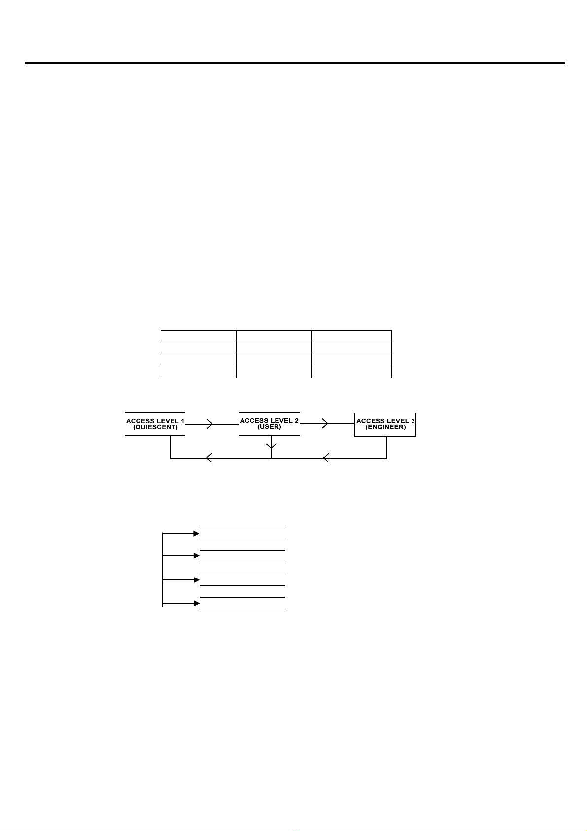
Access Levels
The system menus are set into three access levels as follows. For simple indication the status of the ‘shift LED’
will show the level selected as follows;
Access Level Description Shift LED
1 Normal OFF
2 User ON
3 Engineer FLASHING
Access Level 1 (Normal)
Fault Status
The ‘>faults’ function causes the control panel to display any items which are in fault. One point shows at
a time and the continued pressing of the ‘>faults’ prompt allows the messages to be scrolled through, one
at a time.
Display On
The backlight for the system LCD display switches off after a period of time if the controls are not used.
Whilst the backlight is switched off, the prompt ‘DISPLAYon’ is displayed. The backlight will switch on if
this function is selected or if any other button is pressed.
>FAULTs
DISPLAYon
TestDISP
AL2 CODE

Sita200plus Repeater Panel Installation Instructions
14
Test Display
The ‘testDISP’ function causes the panel LEDs to pulse and the LCD to blacken in order that their correct
operation may be verified.
AL2 Code
The ‘AL2 CODE’ function enables access to Access Level 2 (user level). This is followed by a code entry
prompt, so you will need to enter the code (default 222).
Access Level 2 (User)
Clock Set
The time and date may be set using the ‘CLOCK SET’ function. If these are not set then the panel will not
show the time & date, and the event log will not have a time & date stamp. These settings do not remain
after the complete removal of power, and will need to be re-programmed if the mains and battery power is
allowed to fail.
Minus / Plus One Hour
The time does not automatically adjust for British Summer Time so this feature allows a one hour jump
without having to completely reprogram the time & date.
Exit AL2
The ‘Exit AL2’ prompt returns the control panel to Access Level 1 (Quiescent).
Test Display
The ‘testDISP’ function causes the panel LEDs to pulse and the LCD to blacken in order that their correct
operation may be verified.
AL3 Code
The ‘AL3 CODE’ function enables access to Access Level 3 (engineer level). This is followed by a code
entry prompt, so you will need to enter the code (default 333).
AL2 CODE
Time and date setting
>CONTROL
CLOCK SET
>FAULTs
>EVENT log
Disp
lay current faults
Display event log
>INDICATE
+ 1 HR
-
1 HR
EXIT AL2
Test DISP
AL3 CODE
Advance time by 1 hr
Retard time by 1 hr
Go to Access Level 1 (Normal)
Test LEDs and LCD
Go to Access Level 3 (Engr)

Sita200plus Repeater Panel Installation Instructions
15
From Access Level 2 (user)
Allocate
an add
ress (1
-
4)
AL3 CODE
SetRptr
ID
exitAL3
OSPmode
Go to Access Level 1 (Engr)
Select OSP mode for upload
Fault Status
The ‘>faults’ function causes the control panel to display any items which are in fault. One point shows at
a time and the continued pressing of the ‘>faults’ prompt allows the messages to be scrolled through, one
at a time.
Event Log
The event log stores 255 fire and fault events. These are displayed in text format and may be scrolled
through by pressing the ‘<Events’ / ‘Events> prompt.
Access Level 3 (Engineer)
Set Repeater ID
Only 1 repeater panel can be connected to the Sita200plus control panel. This menu should not be used,
if this option is entered the repeater ID should be set to 1.
Exit AL3
The ‘Exit AL3’ prompt returns the control panel to Access Level 1 (Quiescent).
OSP Mode
The system will only allow an upload or a download to the OSP software programming package when the
‘OSPmode’ is selected.

Sita200plus Repeater Panel Installation Instructions
16
Installation and Commissioning
Installation 1
st
Stage
The installer needs to install the system wiring in the form of a 2-core radial circuit (daisy chain format). The
cabling should be 2 core 1.5mm
2
, screened and fire resistant, of an MICC or FP200 equivalent type.
The cable should remain disconnected from any panels, and must be tested for continuity and integrity with a high
voltage tester, as required for general electrical installations.
The repeater panel back boxes should be mounted, with the mains supply tested, connected and isolated at the
un-switched fused spur, ready for the commissioning.
The installer needs to provide a set of ‘As-Wired’ drawings and proof of cable continuity and insulation test
readings etc., before commissioning may proceed. This information is essential, and may be entered onto the
forms provided at the rear of the manual.
Installation 2
nd
Stage
Once the commissioning engineer is satisfied with the continuity / integrity of the repeater R-Bus cable, the system
may be powered up as follows.
1. Power up and program the main control panel according to the control panel
instructions, leaving the repeater R-Bus disconnected at this stage (see the
Sita200plus Engineering & Commissioning Instructions for further details).
2. Power up the Repeater Panel by applying the 230V AC mains supply, before
connecting the batteries.
3. Select ‘OSPmode’ at Access Level 3 (engineer) and download the control panel
configuration data into the repeater panel.
4. Reset the repeater panel, and exit Access Level 3 (engineer).
5. Connect the Repeater R-Bus at the repeater panel.
.
6. Connect the Repeater Panel R-Bus at the main Control Panel.
7 Select the [RPTmode] button at Access Level 3 (Engineer) at the main control panel.
For control panels Version 4.00 or earlier, the control panel must be powered down
and re-powered at this stage.
8 Check the display to ensure that it successfully locates the repeater panel.
Commissioning
Once the above set up has been completed, the repeater panel should be operative. This must be tested carefully
for correct operation, by activating devices on the main panel and by ensuring that the repeater controls will
silence and reset the alarms.

Sita200plus Repeater Panel Installation Instructions
17
Fault Finding
Summary of Faults
Common Problems
1. R-Bus Integrity Disconnect the R-Bus connector at the panel to enable
testing of the cable. Install a wire link between the R+
and R– connections at the last point in order to be able
to take cable continuity readings, removing it to take
insulation readings.
A reading of approximately 1.2 ohms per 100m of 2c1.5
cable is expected for continuity, and in excess of 1Mohm
is expected for insulation resistance between cores.
Connect the R-Bus at the Control Panel only, and using
an electronic test meter, you should read between 12
and 15v DC on the R-Bus (R+, R-) terminals, at the
repeater panel.
2. No Repeater Panels found Remove power from the Control Panel, and wait 2
minutes.
Ensure that he Repeater Panel is not in OSP mode (Exit
Access Level 3 (engineer) to end).
Power up the Control Panel by applying the 230V AC
mains supply, before connecting the batteries.
Check the display to ensure that it successfully locates
the repeater panel.

Sita200plus Repeater Panel Installation Instructions
18
Technical Data
Repeater Panel
Technical Support
For further technical support please contact your distributor.
Do not call the Fike Safety Technology technical support department unless your distributor has first given their
advice and attempted to rectify the issue.
Technical support will not be available if the instruction manual has not been read and understood. Please have
this instruction manual available whenever you call for technical support.
Due to the complexity and inherent importance of a life risk type system then training on this equipment is
essential. Installation and commissioning should only be carried out by competent persons.
Sita200plus Repeater Panel
Dimensions W x H x D 320mm x 320mm x 90mm
Weight < 5kg
No. of zones 32 zones
Device labels 24 characters
LCD display 6 lines of 42 characters
lines 1-3
lines 4-5
line 6
Fire alarms
fault, disablement & test indication
menu functions & prompts
LED Indication Fire
Fault
Disablement
Test
red
steady in general fire
pulsed (0.3s on, 0.5s off) from an MCP
yellow
intermittent (0.3s 0n, 2.1s off)
pulsed (0.3s 0n, 0.5s off)
yellow
continuous
yellow
pulsed (0.3s on, 0.5s off)
Audible Indication 2.5kHzBuzzer continuous in fire
intermittent (0.3s on, 2.1s off) in fault
Keypad 16 way alphanumeric with 4 ‘soft’ keys for menu operation
Number of Repeater panels maximum of 1 2 core 1.5mm
2
(earth/screen) data link
Inputs and Outputs Fire
volt free contacts
30VDC @ 2A max
Power Supply Inbuilt PSU
Standby batteries
Mains supply
Vmax
Vmin
(deep discharge protection)
Max cont output current
Ripple and noise
Switch Mode power supply and charging circuitry
2 x 3.2 Ah 12V sealed lead acid batteries
230VAC, +10%, -15%
31.5V ±1%
21V
1.0A
<=5% of Vmax
IP Rating 21C

Sita200plus Repeater Panel Installation Instructions
19
Further Information
Battery Calculations
Where: IS = Standby Current
IA = Alarm Current
MP = Multi Point Detector
Item Quantity IS (mA) Tot IS (mA) IA (mA) Tot IA (mA)
Repeater Panel 38.000 52.000
Panel O/P 4 (200mA
max)
- 200.000
Panel O/P 5 (200mA
max)
- 200.000
Aux 24V (45mA max) - 45.000
Totals IStot (mA) A
IAtot (mA) B
Times (hrs) Standby (hrs)
C
Alarm (hrs) D
Current required (mAh) IS (mAh) E
IS (mAh) F
Total Current (mAh)
E + F = G
Total Current (Ah)
G / 1000 = H
Battery requirement (Ah)
H x 1.25 = J

Sita200plus Repeater Panel Installation Instructions
20
Installation Checklist
Use the following checklist to ensure that your work is correct and that the commissioning engineer has the
necessary information to complete the commissioning of the system
The commissioning engineer will require this sheet, along with ‘Cable Continuity and Insulation Test Results’,
correctly marked ‘as-wired’ drawings and completed ‘Configuration sheets’, before attending site to commission
the system.
Stage 1
Description
Installation
Engineer Checked
Commissioning
Engineer Checked
R-bus cable installed correctly, clipped or in
containment.
R-bus cable stripped to aprox 500mm, teminated into
temporary connector blocks.
DO NOT CONNECT TO PANEL YET.
Repeater Panel back box installed with 230v AC
supply live, tested and isolated locally
Control Panel back box installed with 230v AC
supply live, tested and isolated locally
Cable insulation and continuity testing complete, and
form filled out.
As-wired drawing marked up showing cable runs and
devices.
Configuration sheets completed with devices
descriptions etc.
Site Name & Address:
Installation Company:
Testing Engineer:
Signature:
Date:
Other manuals for SITA200plus
1
Table of contents
Other Fike Repeater manuals

Popular Repeater manuals by other brands

Westell
Westell Modular 255 Series user guide

Exibel
Exibel WRE6505 v2 quick start guide

Futurecom
Futurecom PDR8000 Programming guide

Andover Controls
Andover Controls InfiLink 200 installation guide

Motorola solutions
Motorola solutions Futurecom PDR8000 Programming guide

TAPKO
TAPKO MECtp operating instructions


