WayPoint17A Series Installation Guide - 3 -
Installation Instructions:
Unit shall be installed in accordance with The National Electrical Code and all applicable Local Regulations.
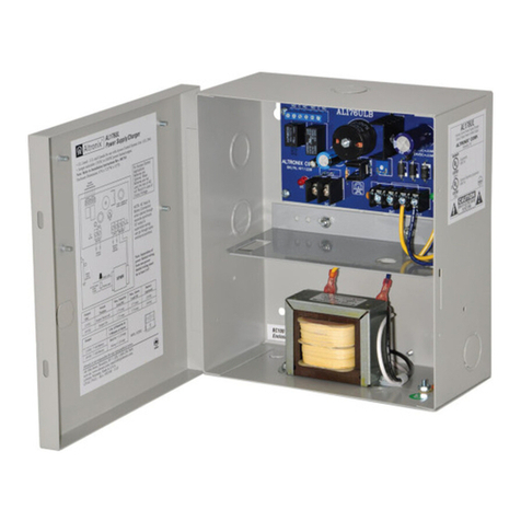
1. Remove backplane from enclosure prior to mounting (do not discard hardware).
2. Mark and drill desired inlets on the enclosure to facilitate wiring (Fig. 1, pg. 4).
Note: Inlets for conduit fittings should only be made on the bottom of the enclosure.
UL Listed NEMA type 4X rated conduit connector/hubs shall be used for the appropriate size inlets.
3. Mount unit in desired location. Mark and drill holes to line up with the top and bottom holes of the
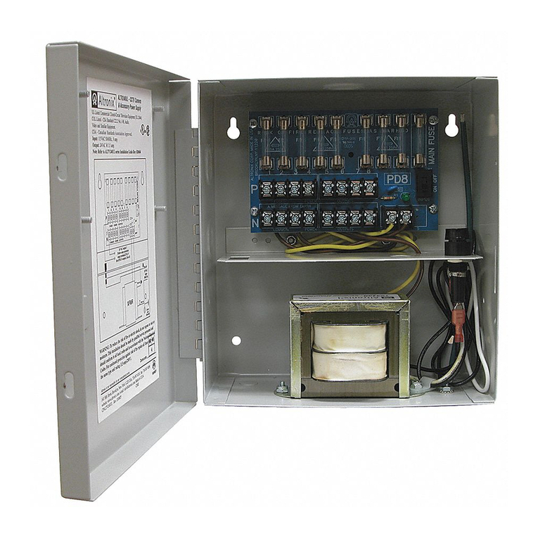
enclosure flange. Secure enclosure with appropriate fasteners (Fig. 5, pg. 8 and Fig. 11, pg. 8).
4. Mount back plane to enclosure with hardware.
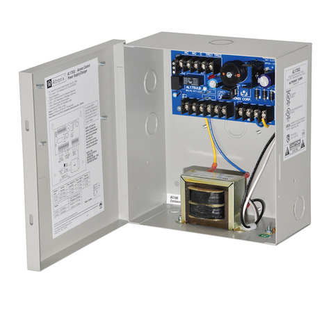
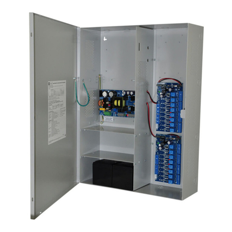
5. Set the input voltage selector switch for 115VAC or 230VAC operation (Figs. 2-4, pgs. 5-7)
6. To facilitate wire entry utilize weather-tight NEMA 4 rated connectors, bushings, and cable.
7. Set illuminated master power disconnect circuit breaker to the [OFF] position (Figs. 2-4, pgs. 5-7).
8. Connect unswitched AC power (115VAC/230VAC, 50/60 Hz) to terminals marked [L, N]
(Figs. 2-4, pgs. 5-7). Green branch wire connects to earth (safety) ground lug .
Wire gauge range of connectors is 14 AWG to 11 AWG (1.6 mm to 2.5 mm diameter).
9. Set illuminated master power disconnect circuit breaker to the [RESET/ON] position (Figs. 2-4, pgs. 5-7).
10. WayPoint17A4U/A4DU, WayPoint17A8U/A8DU are factory set for 24VAC operation.
For 28VAC operation adjust unit prior to mounting and applying power as follows:
Change the wire position so that the black wire [28V] is connected to the terminal marked [P] and
the yellow wire [24V] is connected to the terminal marked [S].
11. Measure output voltage on terminals marked [COM, 24V, 28V] on WayPoint17AU or WayPoint17ADU
(Fig. 2, pg. 5) or [1-4] or [1-8 COM] on WayPoint17A4U, WayPoint17A4DU, WayPoint17A8U and
WayPoint17A8DU before connecting devices (Fig. 3, pg. 6, Fig. 4, pg. 7).
This helps avoiding potential damage.
12. Set illuminated master power disconnect circuit breaker to the [OFF] position (Figs. 2-4, pgs. 5-7).
13. Connecting devices to WayPoint17AU or WayPoint17ADU:
For 24VAC output connect devices to terminals marked [COM, 24V] (Fig. 2, pg. 5).
For 28VAC output connect devices to terminals marked [COM, 28V] (Fig. 2, pg. 5).
Connecting devices to WayPoint17A4U or WayPoint17A4DU:
Connect device to terminals marked [1-4] and [COM] (Fig. 3, pg. 6).
Connecting devices to WayPoint17A8U or WayPoint17A8DU:
Connect device to terminals marked [1-8] and [COM] (Fig. 4, pg. 7).
14. Set illuminated master power disconnect circuit breaker to the [RESET/ON] position (Figs. 2-4, pgs. 5-7).
15. LEDs will illuminate indicating each output is powered (Figs. 2-4, pgs. 5-7).
16. Upon completion of wiring secure enclosure door with latches and optional lock.
Caution: Equipment to be installed / serviced by authorized / trained personnel only.
Shut branch circuit power before installing / servicing equipment.
WARNING: When installing in a non-restricted service area use lock or other fastened means on door
latches. This installation should be made by qualified service personnel and should conform to the
National Electrical Code and all local codes.
CAUTION
HIGH VOLTAGE
COM 24V 28V COM 24V 28V
COM 24V 28V COM 24V 28V
28V 24V COM
PD2WP
PD2WP
Input Voltage
Power Input
115V
115
230
LG N
5
5
5
5
28V 24V COM
Input Voltage
Power Input
115V
115
230
LG N
Used on WayPoint17ADU
Ground
Lug
ALTRONIX CORP.
www.altronix.com
BROOKLYN,NY 11220
ALTRONIX CORP.
www.altronix.com
BROOKLYN,NY 11220
