manuals.online logo
Brands
  1. Home
  2. •
  3. Brands
  4. •
  5. IBM
  6. •
  7. Power Supply
  8. •
  9. IBM SCM User manual

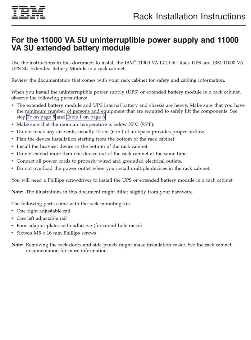
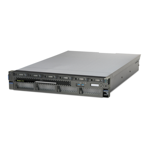
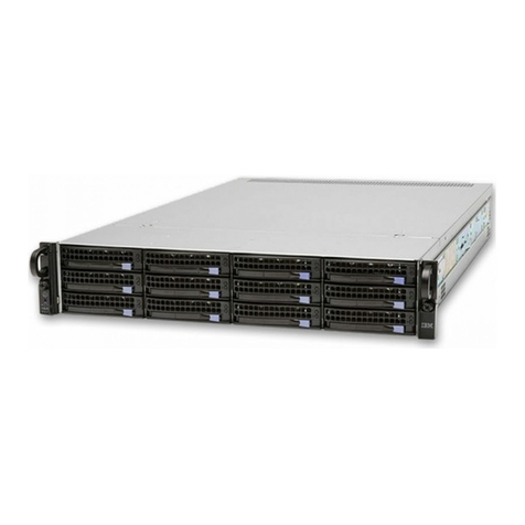
IBM SCM User manual

Power Systems
SCM
IBM
Power Systems
SCM
IBM
ii Power Systems: SCM
Remove SCM
To remove a SCM, complete the following steps:
1. When the node being serviced is above EIA location 29U, the ladders must be used while
installing or removing the rear and front FRUs and cables.
2. Perform the following procedure on ONLY THE FRU(s) BEING SERVICED. The following images
are generic and do not represent the literal location being serviced.
3. Modifying FRU locations which are not called out for service can have adverse effects on the
system, INCLUDING SYSTEM OUTAGE AND LOSS OF DATA.
4. The torque tool (P/N 41V1059) is required for this procedure. The torque tool was initially shipped
with the system.
5. CAUTION: If the system slide rails are installed above EIA location 29U, two Support Services
Representatives (SSRs) must perform the procedure together and the following equipment must be
used as a safety precaution for servicing: ServerLIFT tool (P/N 74Y4399), two Hard hats (P/N
5442867) and two service-qualified ladders (P/N 46G5947 and P/N 00E4866)
1. Remove front bezel
a. Remove the front bezel (A) from the system node being serviced and all system nodes which
share the same system control unit with the system node being serviced.
A
b. If present, remove the retention screws (A) from the front of the system node.
© Copyright IBM Corp. 2014 1
2. Unplug all power supply cables
Note: The following step applies to the system node being serviced and all system nodes which
share the same system control unit with the system node being serviced.
a. Locate the system control unit for the system being serviced.
b. Validate which system nodes are connected to the system control unit by visually tracing /
checking the clock cables.
c. Disconnect the power supply cables from each power supply of each affected system node.
3. Remove all power supply units
a. Push tab (A) down of the power supply being serviced and pull it towards the direction of the
arrow shown. Keep pulling until the power supply unit slides out from the slot.
2Power Systems: SCM
A
4. If an S-Biner power cable routing clip is present: While keeping the power cable correctly routed
through the S-Biner, unclip all S-Biners from the node being serviced.
5. Unplug line cords
a. Unplug the line cords from only the system node being serviced.
Remove SCM 3
6. Move cable management arm up
a. Pull out the retention pins (B) and rotate the cable management arm up on the pivot point (A)
from position (2) to position (1).. The pins will automatically retract into the locking position
when the arm is properly located in the up position.
A
B
1
2
7. Remove all PCI cables
4Power Systems: SCM
a. Make note of the location from which each PCI cable is removed. They must be plugged into the
same location when reinstalled.
b. Label and unplug the PCI cables from the system node being serviced.
8. Remove all SMP cables
a. Make note of the location from which SMP cable is removed. They must be plugged into the
same location when reinstalled.
b. Use the torque tool (41V1059) and turn in the direction indicated to unlock. There is a stop to
prevent over rotation. Visually confirm that the SMP cable camming mechanism is in the
unlocked position and that the black dots are showing through the two holes at the 5 and 11
o'clock positions before pulling on the cable.
Remove SCM 5
c. Label the SMP cables so they may be plugged back into the same slots.
d. Grip the pull tab and pull in the direction indicated to remove the SMP cables.
9. Remove all clock card cables
a. Make note of the location from which each clock card cable is removed. They must be plugged
into the same location when reinstalled.
6Power Systems: SCM
b. Remove the clock card cables from the system node by pushing the clock cable in slightly, then
pull the locking tab to release the latch and pull cable out.
c. Remove the clock card cables from the system control unit by pushing the clock cable in slightly,
then pull the locking tab to release the latch and pull cable out.
10. If present, remove the retention screws (A) from the rear of the system node.
Remove SCM 7
A
11. Position lift tool
Note: If the system slide rails are installed at or below EIA location 29U, skip to the next step.
a. With both SSRs wearing hard hats, position the ladders and the lift tool as shown in the graphic.
The lift tool should be about one foot away from the rack with its platform slightly below the
bottom of the system drawer to account for the slight downward flex when the drawer is
extended out fully on its slides.
8Power Systems: SCM
12. Set system into service position
Note: When placing the system into the service position, it is essential that all stability plates are
firmly in position to prevent the rack from toppling.
Note: Ensure that only one system node is in the service position at a time.
a. While holding down the system node release latches on both the left and right sides, pull the
system node out from the rack until the rails are fully extended and locked.
Note: When the system node rails are fully extended, the rail safety latches lock into place. This
action prevents the system node from being pulled out too far.
b. While holding down the system node release latches on both the left and right sides, pull the
system node out from the rack until the rails are fully extended and locked.
13. Secure node with lift tool and position ladder
Note: Perform the following step with the help of another SSR only if the slide rails of the node
being serviced are above EIA location 29U.
a. Gently raise the lift tool platform to stably contact the bottom of the drawer, minding not to over
force it as it could put upward stress on the slide rails.
b. While using the ladder, do not lean on or against the system drawer or lift tool during service,
and follow safe practices.
c. Disengage the front two pins by elevating the front of the tilt table using the table lift handle.
d. Manually push the system forward slightly away from the rack.
e. Raise the lift tool to disengage the rear pins.
f. Push the sliderails in and then level the tilt table.
g. Lower the lift tool to perform the service action at a lower height.
Remove SCM 9
Note: Some pictures in the procedure from this step onward show the node on slide rails. This
should be ignored because the system has been removed from the rails and is positioned on the
lift tool.
14. Remove Top Cover
Note: The following steps apply only to the system node being serviced.
a. Lift up the cover latch.
b. Lift the cover off the system.
10 Power Systems: SCM
15. Press the Blue Locate Button
Note: The blue locate button can be used to activate the identify LED(s) on the FRU(s) being
serviced, even after the system has been put into service position. It is optional to activate the
identify LED(s) at this time. It may be done any time during the procedure as a reminder of which
FRU(s) is being serviced. The capacitor only holds enough of a charge to activate the LED(s) for
around 30 seconds.
a. Press and hold down the button (A) on the Power APSS card to temporarily activate the identify
LED(s) on the FRU(s) being serviced. This LED(s) will remain active while the button is pressed.
b. The locate button on either Power APSS card may be used.
Remove SCM 11
16. Inspect the Thermal Interface Material (TIM)
a. Inspect the TIM on the heat sink for visible signs of damage. It must be flat and centered on the
heat sink WITH NO FOLDS. Small wrinkles are acceptable.
b. If the TIM is not flat, is not centered, or has folds in it, it is considered damaged.
Note: If the TIM is Indium or Hitachi, it is fixed to the heat sink. In this case, if the TIM is
damaged, the entire heat sink module of the failing system processor module must be replaced. If
the TIM is Dexerials, it is not fixed to the heat sink. In this case, the heat sink can be used
regardless of the state of the TIM. In case of a Dexerials TIM, discard it if it's damaged,
otherwise, move it with tweezers to the Electrostatic Discharge (ESD) surface. Make sure that the
surface is clean.
12 Power Systems: SCM
17. Remove the Heat Sink from the SCM
Note: The heat sink MAY BE HOT.
a. One or more SCMs will need to be removed during this procedure. There are two versions of the
SCM removal tools available. The newest version has a "loop" for easier handling.
b. Loosen the heat sink actuation screw by turning the nut driver (P/N 46K5039) counterclockwise
(A) until the screw becomes loose and moves freely.
c. Grip the heat sink (B) by the grooves on opposing sides and remove it by lifting straight up.
d. Place the heat sink upside down on an ESD surface.
Note: If any dust/debris is to be removed from heat sink, it must be done in another room or
greater than 25 feet (7.62 meters) away from work area.
Remove SCM 13
A
B
18. If dust or debris is present, use an air bulb to clean by blowing small bursts of air from the center
toward the sides of the SCM.
Note: Do NOT touch any contact surfaces.
19. Remove the SCM
Note: SCM tool (A) (P/N 01AF095) or (B) (P/N 00E8472) may be used to handle the SCM.
14 Power Systems: SCM
20. Prepare SCM tool
a. Press down on the center button. (A).
b. While pressing the button (A), squeeze the tabs (B) together.
c. Release the center button (A) while still holding the tabs (B) so that the tabs (B) are held in the
locked position.
Note: This will place the jaws at the bottom of the tool in the open position.
Remove SCM 15
A
B
21. Prepare for SCM Removal
a. Using the SCM tool, align the beveled corner (A) of the tool over the beveled corner of the
module.
b. Lower the tool over the SCM, ensuring the guide pins (B) are inserted into the alignment holes.
A
B
B
B
22. Remove the SCM.
a. Ensure that the CP SCM tool latches (A) are open.
16 Power Systems: SCM

Other IBM Power Supply manuals

IBM S922L Instruction Manual

IBM

IBM S922L Instruction Manual

IBM S822L User manual

IBM

IBM S822L User manual

IBM POWER 730 User manual

IBM

IBM POWER 730 User manual

IBM 9080-M9S User manual

IBM

IBM 9080-M9S User manual

IBM 170 Servers User manual

IBM

IBM 170 Servers User manual

IBM System/370 145 Service manual

IBM

IBM System/370 145 Service manual

IBM Power Systems 8005-12N Instruction Manual

IBM

IBM Power Systems 8005-12N Instruction Manual

IBM GX7000 Series Guide

IBM

IBM GX7000 Series Guide

IBM S824L Instruction Manual

IBM

IBM S824L Instruction Manual

IBM S812 Instruction Manual

IBM

IBM S812 Instruction Manual

IBM 3000VA User manual

IBM

IBM 3000VA User manual

IBM 9223-22H User manual

IBM

IBM 9223-22H User manual

IBM Power System 9009-41A User manual

IBM

IBM Power System 9009-41A User manual

IBM Power System 9009-41A User manual

IBM

IBM Power System 9009-41A User manual

IBM Power System AC922 User manual

IBM

IBM Power System AC922 User manual

IBM Power System L922 User manual

IBM

IBM Power System L922 User manual

IBM Power 720 Express 8202-E4B User manual

IBM

IBM Power 720 Express 8202-E4B User manual

IBM 11000 VA LCD 5U User manual

IBM

IBM 11000 VA LCD 5U User manual

IBM 7199-92X User manual

IBM

IBM 7199-92X User manual

IBM Power System IC922 User manual

IBM

IBM Power System IC922 User manual

IBM I 7.1 Installation guide

IBM

IBM I 7.1 Installation guide

IBM 9009-22A User manual

IBM

IBM 9009-22A User manual
IBM 9006-12C User manual

IBM

IBM 9006-12C User manual

IBM SAS RAID controllers User manual

IBM

IBM SAS RAID controllers User manual
Popular Power Supply manuals by other brands

Zendure Satellite Monitor CT installation manual

Zendure

Zendure Satellite Monitor CT installation manual

Neumann.Berlin BS 48 i owner's manual

Neumann.Berlin

Neumann.Berlin BS 48 i owner's manual

Televes MATV 5021 manual

Televes

Televes MATV 5021 manual

MSI MEG Ai1300P PCIE5 user guide

MSI

MSI MEG Ai1300P PCIE5 user guide

Tiptop Audio ZEUS Series microZEUS user guide

Tiptop Audio

Tiptop Audio ZEUS Series microZEUS user guide

Trinabess Trinahome T Series installation manual

Trinabess

Trinabess Trinahome T Series installation manual

Samlexpower SEC-1235 Installation & operating manual

Samlexpower

Samlexpower SEC-1235 Installation & operating manual

Videotec OHEPS19B instruction manual

Videotec

Videotec OHEPS19B instruction manual

EA-ELEKTRO-AUTOMATIK PS 2042-06B instruction manual

EA-ELEKTRO-AUTOMATIK

EA-ELEKTRO-AUTOMATIK PS 2042-06B instruction manual

Puls CP10 Series instruction manual

Puls

Puls CP10 Series instruction manual

BEL LDN120 Series installation instructions

BEL

BEL LDN120 Series installation instructions

AP&T AP-AB1208 manual

AP&T

AP&T AP-AB1208 manual

Kikusui PWR400L Operation manual

Kikusui

Kikusui PWR400L Operation manual

Honeywell SILENT KNIGHT SK-PS6 instruction manual

Honeywell

Honeywell SILENT KNIGHT SK-PS6 instruction manual

EMC2 302-000-589 Disassembly instructions

EMC2

EMC2 302-000-589 Disassembly instructions

Panasonic 4466 Technical description

Panasonic

Panasonic 4466 Technical description

Pyramid PS15K.5 user manual

Pyramid

Pyramid PS15K.5 user manual

BEL LDN240 Series installation instructions

BEL

BEL LDN240 Series installation instructions

manuals.online logo
manuals.online logoBrands
  • About & Mission
  • Contact us
  • Privacy Policy
  • Terms and Conditions

Copyright 2025 Manuals.Online. All Rights Reserved.