Filser Electronic ATR833 User manual
Filser Electronic GmbH
ATR833
VHF COMMUNICATION TRANSCEIVER
[ 12 ]
TX
35
OPERATION MANUAL
Doc. No.: 0140.010.11
REVISION 1.2
19. October 2004

Page: 2
Contents
1SECTION 1 - GENERAL INFORMATION...................................... 3
1.1 INTRODUCTION....................................................................... 3
1.2 Manufacturer: .......................................................................... 3
1.3 DESCRIPTION OF EQUIPMENT.............................................. 3
1.4 TECHNICAL CHARACTERISTICS........................................... 4
2OPERATIONAL INSTRUCTIONS.................................................. 7
2.1 Turn On/Off .............................................................................. 7
2.2 Volume control ........................................................................ 9
2.3 Squelch level control .............................................................. 9
2.4 VOX level control for Intercom............................................... 9
2.5 Frequency set ........................................................................ 10
2.6 Modes..................................................................................... 10
2.6.1 Normal Mode (Memory selector) ........................................................... 10
2.6.2 USER Mode........................................................................................... 10
2.6.2.1 SAVE , use of Index..................................................................................11
2.6.3 DATA Mode ........................................................................................... 11
2.7 Download............................................................................... 12
2.8 Low-battery............................................................................ 12
2.9 Automatic frequency control................................................ 12
2.10 Transmitting .......................................................................... 13
2.11 Receiving indication ............................................................. 13
3REMOTE CONTROL ................................................................... 13
4ATR833 OPERATING CONTROLS ............................................. 15
5ATR833 FREQUENCY-CHANNEL PLAN FOR COMBINED 8.33
KHZ /25 KHZ OPERATION ......................................................... 16
6DIMENSIONS .............................................................................. 17
7APPROVAL ................................................................................. 18

Page: 3
1 SECTION 1 - GENERAL INFORMATION
1.1 INTRODUCTION
This manual contains information relative to the physical, mechanical,
and electrical characteristics of the ATR833 VHF Communications
Transceiver including operating procedures.
Information relative to the installation can be found in the ATR833
Installation Manual. (Document Number 01.140.010.12)
Information relative to the maintenance, alignment , and procurement
of replacement parts may be found in the ATR833 Maintenance
Manual (Document Number 01.140.010.13).
1.2 Manufacturer:
Filser Electronic GmbH located in:
Gewerbestrasse 2, 86875 Waal, GERMANY
Phone: +49 (0) 8246 9699-0
Fax: +49 (0) 8246 1049
Web: http://www.filser.de
Email: info@filser.de
1.3 DESCRIPTION OF EQUIPMENT
The ATR833 COM Transceiver consists electrically of five sections:
Receiver transmitter board, AF Stage board, Antenna board, display
circuitry, and the microprocessor board.
The ATR833 operates at 14VDC and features typically 6 Watts of
transmitter power. It can also be operated down to 9VDC with reduced
RF power (emergency operation).
The ATR833 is a Dual Mode Airband Transceiver, that can operate
with 8.33 kHz/25 kHz channel spacing, plus a ’25 kHz only’ mode.
(see also “General Setup” in installation manual)
The frequency range is 118.000 to 136,975 MHz, channel spacing
8,33 kHz/25 kHz, results in 2.278 channels, or 118.000 to 136,975
MHz, channel spacing 25 kHz, results in 760 channels.
It is a single block unit with 57 mm diameter for instrument panel or
console mounting.

Page: 4
The ATR833 has the capability of programming up to 100 memory
channel frequencies for later recall. Each frequency can be given a
name of 8 characters .
The unit also has the capability to store a database for the whole of
Europe. A fast access method enables one to find quickly any
frequency by name.
The data base is an add on feature and not a basic function of the
ATR833. If it is not installed or it has been erased by a special setup
the ATR833 operates like any standard COM radio using an active
and stand by display pattern. The only additional feature is the user
memory and the possibility of adding names.
To prevent accidental long term transmission the transmitter
automatically turns off after two minutes (for example, when a TX
button becomes stuck ON).
1.4 TECHNICAL CHARACTERISTICS
SPECIFICATION CHARACTERISTIC
ETSO COMPLIANCE: ETSO-2C37e, ED-23B Class 6
ETSO-2C38e, ED-23B Class E
TSO COMPLIANCE: TSO-C37d, RTCA DO-186A Class 6
TSO-C38d, RTCA DO-186A Class E
LBA Certification Number O.10.911/107 ETSO
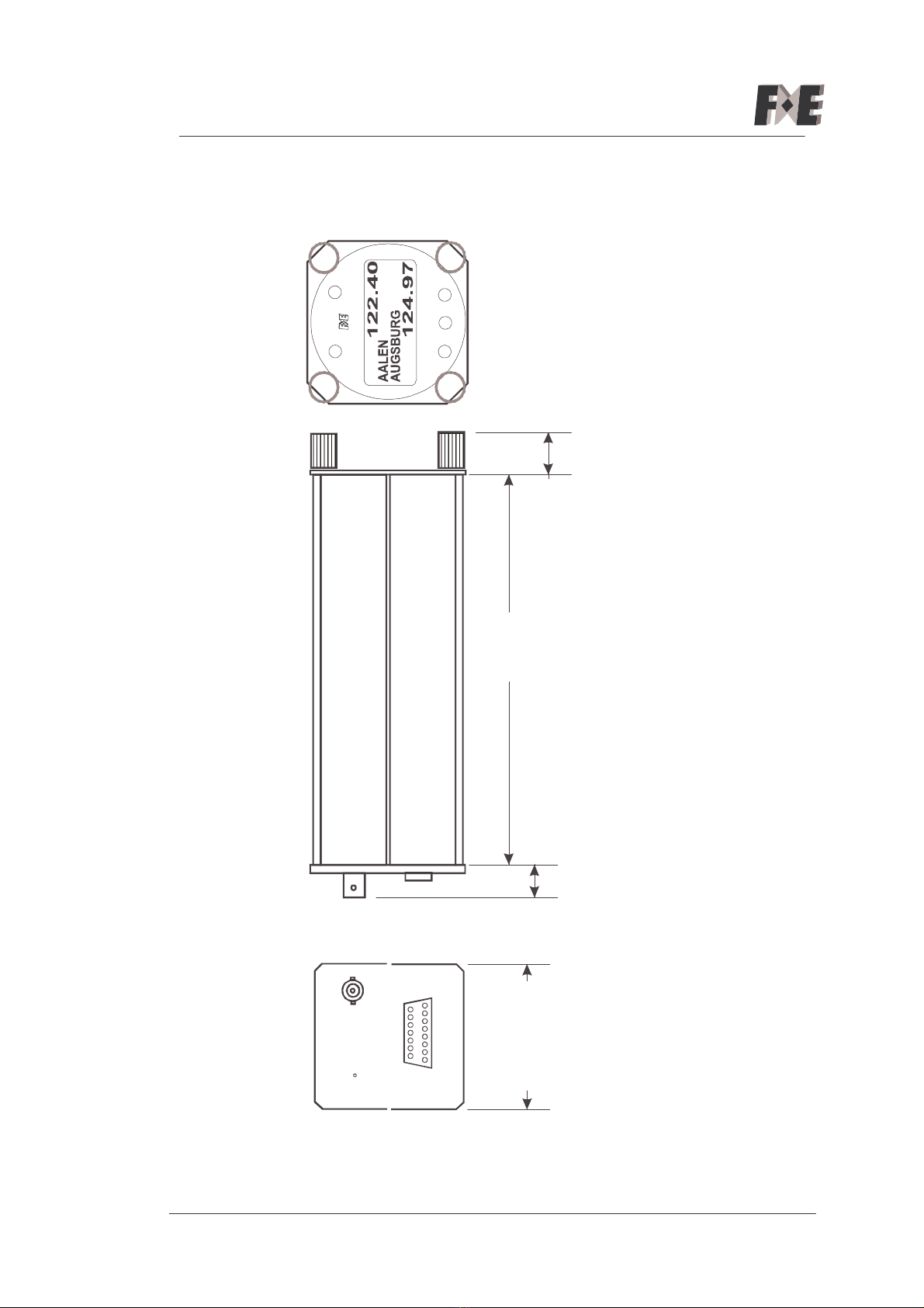
PHYSICAL DIMENSIONS:
Height: 2.56 in (6,5 cm)
Width: 2.56 in (6,5 cm)
Depth (behind aircraft panel): 8.66 in (22 cm)
WEIGHT: 1,55 lbs (0,7 Kg),
MOUNTING: Panel mounted, no shock mounting
required
TEMPERATURE RANGE: -- 2 0 °C to +55°C with short t erm
operation at +70°C
POWER REQUIREMENTS: 14VDC (9 to 15VDC)
Receiver: 0.1 A at standby, max. 0.5A
Transmitter: 2.5A

Page: 5
FREQUENCY RANGE: 118.000 MHz to 136.975 MHz
NUMBER OF CHANNELS 760 for 25 kHz channel spacing
2278 for 8.33 kHz channel spacing
CHANNEL SPACING 8.33 kHz / 25 kHz or 25 kHz
FREQUENCY STABILITY: ±5ppm in the temperature range --20°C to +55°C
DESIGN: All solid state, Printed circuit board
and point to point wiring.
TRANSMITTER
POWER OUTPUT: 6 Watts typical
4 Watts minimum
MODULATION: 70% modulation capability with 98% limiting.
Less than 10% distortion at 85% modulation.
SIDETONE OUTPUT: 100mW into 500Ωheadphones
MICROPHONE: Standard carbon dynamic mic. containing
transistorized preamp. Must provide 100mVRMS
into 100Ωload. Or Electret. Microphone gain
adjustment is also provided
HARMONIC CONTENT: Greater than 60dB down from carrier.
DUTY CYCLE: 2 min. on, 4 min. off, auto-turn off after 2 min.
RECEIVER
RECEIVER SENSITIVITY: 2.5µV(hard) will produce not less than 6dB S+N/N with
1KHz tone modulated 30%
RECEIVER SELECTIVITY: -6dB bandwidth at not less than fc ±8.0 kHz.
for 25 kHz channel spacing -40dB bandwidth at not more than fc ±17.0 kHz
-60dB bandwidth at not more than fc ±25.0 KHz
RECEIVER SELECTIVITY: -6dB bandwidth at not less than fc ±2.78 kHz.
for 8.33 kHz channel spacing -60dB bandwidth at not more than fc ±7.37 KHz
RECEIVER OUTPUT: 4 W minimum into 4Ω.
AGC CHARACTERISTIC: From 10 µV to 10,000 µV audio output will not
vary more than 3dB.

Page: 6
SQUELCH: Automatic squelch (adjustable carrier--to--noise
setting) with manual disable.
SPURIOUS RESPONSES AND
CROSS MODULATION PRODUCTS: At least 80dB down.
INTERCOM INPUT: The mic. is connected to the intercom input. The
receiver is operational and mic. audio appears at
the audio output along with receive audio.
100mVRMS of mic. audio is required for 100mW
output.
Special features
DISPLAY : the Display is back lit and adjusts itself automatically for the
ambient light.
MEMORY FOR DATABASE: max. 64 000 byte (EEPROM)
REMOTE CONTROL: For use in tandem gliders a 57mm diameter certified remote
control unit can be connected to the radio.
DATA INTERFACE: RS 232 for PC interfacing for download
of a data base and for connection of a
remote control head.
Page: 7
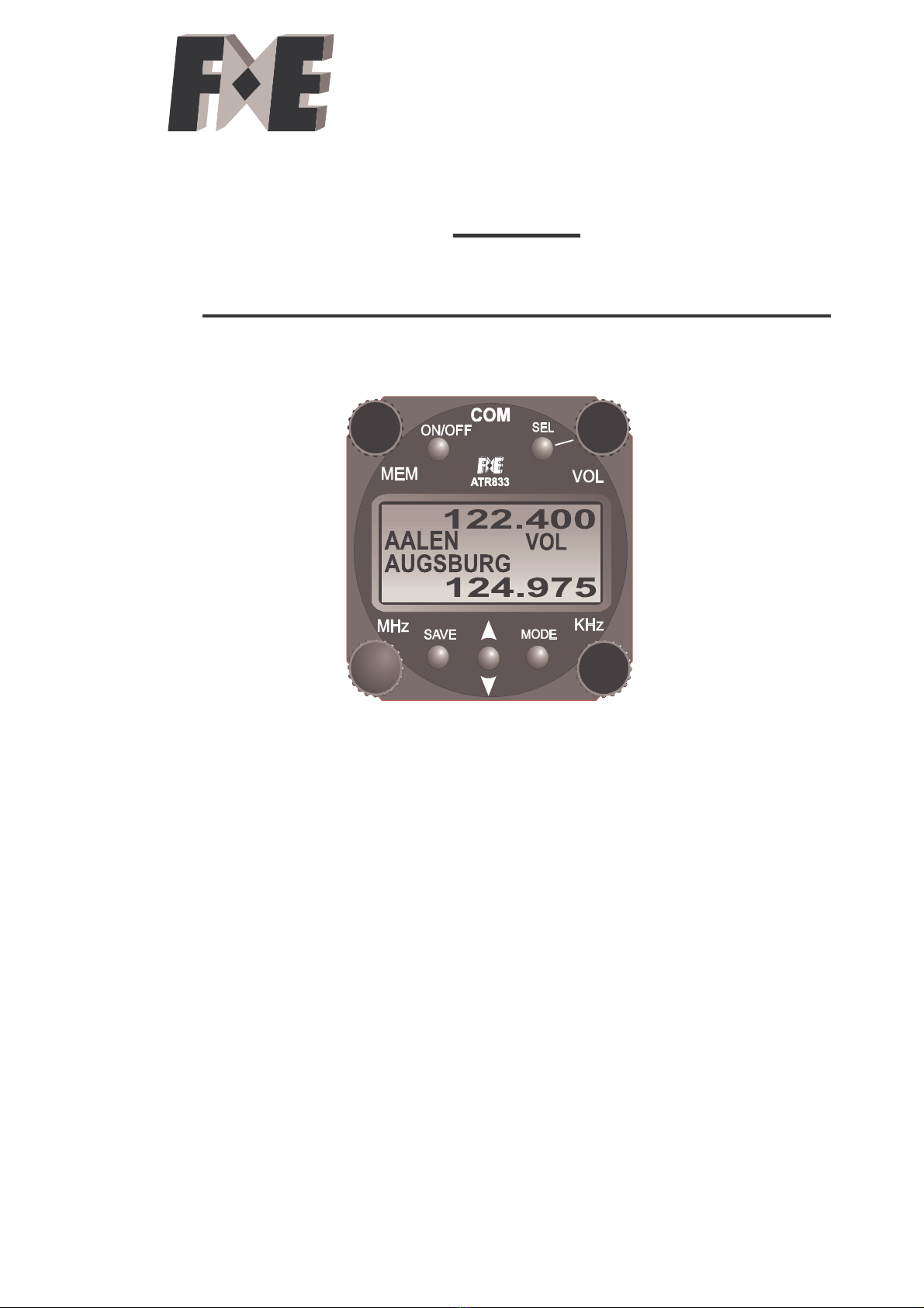
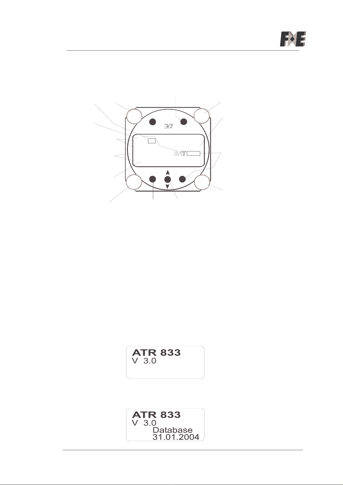
2 Operational Instructions
SEL
MODE
SAVE
ON/OFF
122. 400
124. 975
VOL
AALEN
[ 12 ]
AUGSBURG
TX 26
Active area
Stand by area
Index of
memory
Flag for
Transmitt,
Receive
Area for
Volume,
Squelch,
VOX
Mode: ____, USER, DATA
____ = normal Mode (Frequency set)
USER= User memory
DATA = Search in database
12
43
2.1 Turn On/Off
The “ON-OFF“-button is mounted on the left-top of the unit. The radio
is active, when the button is pressed for a short time (0,5 sec.). To
turn it off the button has to be pressed for more then 3 sec. Also a
break in the master power (master switch) will turn off the radio.
If the power supply is disconnected for a time of up to 5 sec the radio
will reboot with the same status as it was. The active and passive
frequencies will stay as they where before disconnection.
If the power supply is disconnected for longer than 5 sec you have to
switch the radio On again.
After turn on, the display shows type of unit and software version:
If a database is loaded an additional indication appears with
information about the last update:

Page: 8
To enter the INIT-mode for erasing the database and setting up all
defaults
( for VOL,SQU,VOX and user memory) hold the SAVE button pressed
in whilst turning the radio on. (see also “General Setup” in Installation
Manual).
The indication MIC06 shows the general and actual microphone level
(see “Microphone connection” in Installation Manual).
To go to Erase Menu press MODE button.
To go to Channel Space Menu press UP/DOWN button.
To leave Setup press SAVE button.
Erase Menu:
1. To erase Database, press MODE button.
2. To erase User Memory, press UP/DOWN button.
3. To skip erasing and to go to main menu, press SAVE button.
Channel Space Menu, active is marked with (X):
1. To select 25kHz steps, press MODE button.
2. To select 8,33kHz/25 kHz steps, press UP/DOWN button.
3. To return to main menu, press SAVE button.
Note: The kHz stepping for the 8.33 kHz/25 kHz mode and the 25 kHz
only mode is described in chapter 5

Page: 9
2.2 Volume control
The Volume mode is the next default selection (Display shows VOL:
01 to 32). By turning the VOL knob (2) the Volume can be changed to
the desired volume. If another mode is selected (SQ or VOX) the unit
will go back to the Volume mode after any other operation such as
frequency selection. The selected level will be stored for the next time
the set is turned on.
2.3 Squelch level control
Push the SEL button once to get into the Squelch mode (Display
shows SQ: 01 to 10). By turning the VOL knob (2) the Squelch setting
can be changed to the desired level. The unit will change to VOLUME
mode, if a another frequency is selected or to the VOX mode if the
SEL push-button is pressed again.
The selected level will be stored for the next time the ATR833 is
turned on.
The normal Squelch setting is about 3 to 5. With higher settings weak
signals may not be heard. The Squelch setting has no influence on the
intercom although it still operates normally for a received signal.
2.4 VOX level control for Intercom
Push the SEL button twice to get into the Intercom mode (Display
shows VOX: 01 to 10). By turning the VOL knob (2) the Intercom
setting (noise level to turn on the intercom by voice) can be changed
to the desired level. The unit will change to VOLUME mode if another
frequency is selected or if the SEL push-button is pressed again.
The selected level will be stored for the next time the set is turned on.
The higher the selected value is, the louder you have to talk to open
the Intercom VOX.
Note: The Volume control described in 2.2 adjusts the received signal
only and not the Intercom level.

Page: 10
2.5 Frequency set
To set a new frequency just turn the knob (4) for MHz and (3) for kHz
as indicated in the lower stand by line. The kHz stepping for the 8.33
kHz/25 kHz mode is described in chapter 5, ATR833 Frequency-
Channel Plan.While entering a new frequency the previous related
name will be automatically erased.
The index change from [nn] to >nn< indicates that the standby
frequency may be different to the contents of the index stored in the
memory.
To make this frequency active press CHANGE to exchange the new
frequency with the previous active one. The frequency in the upper
window is always the active one.
Note: On the new 8.33 kHz channels the displayed frequency slightly
differs from the real operating frequency. This is described in chapter
5, ATR833 Frequency-Channel Plan.
2.6 Modes
There are basically two modes (Normal and USER) and one extra
mode (DATA), indicated on the right side of the display.
In the normal operation mode USER or DATA is not shown in the
display. After termination of any operation in mode USER or DATA
mode an automatic reset to the normal mode will occur.
The normal mode is for direct frequency input just like many other
COM-radios. The modes can be selected by the MODE button.
2.6.1 Normal Mode (Memory selector)
In this mode the frequency of the stand by display can be changed.
Also the memory selector knob, MEM (1), located in the upper left of
the unit, is used for selecting previous stored frequencies or for saving
a frequency on one of the 100 memories. After using MEM the actual
index number [nn] in use is indicated at the bottom left of the LCD.
2.6.2 USER Mode
In the mode USER, the knobs (3) and (4) are used to set letters for
generating a name for the previous frequency shown in the stand by
line.

Page: 11
With the knob (3) a cursor can be set in the name line and with (4) a
letter can be selected.
The memory selector (1) is disabled in this mode.
2.6.2.1 SAVE , use of Index
Before saving any information into the user memory you should pay
attention to the previous contents represented by the index [nn]
(nn = 0…99). If [nn] is displayed the indication for standby shows
the contents of nn.
If >nn< is displayed the standby indication may be different from the
contents of nn.
By changing the standby frequency or selecting the mode USER
mode the index will change to >nn< .
To save a new frequency and name into the memory (addressed by
index) just press SAVE . For acknowledgement “SAVE” will appear on
the frequency display for 2 seconds. After save the normal mode will
be entered again and the index becomes [nn].
2.6.3 DATA Mode
DATA mode can only be selected if a frequency data base is installed.
To select any frequency by name use the knobs (3) and (4) for finding
any name quickly.
With the knob (3) a cursor can be set in the line of the name and with
(4) a letter can be selected.
Start with the cursor position at the very left:
By rotating (4) (generating the first letter of a name ) immediately the
name in the alphabetic sequence and the related frequency will be
displayed.
After moving the cursor to the next position on the right and selecting
new letters at this position subsequent names and frequencies will
appear. So with three or four steps the required memory frequency
can be called up.
At any time by using the memory selector knob (1) the adjacent
entries of the selected position in the data base can be selected.
To set the selected frequency to active just press CHANGE. The new
frequency then appears in the active line, the old active will be in the
passive line.

Page: 12
The index changes from [nn] to >nn< to indicate that the standby
frequency may be different to the contents of the index.
The mode changes to normal mode.
To store the selected frequency in the user memory select USER
mode (before CHANGE) and press SAVE. Check nn before saving to
avoid unintended overwriting.
2.7 Download
For download of the database you need to use any PC or Notebook to
run a special transfer software with an updated database. The
database and the transfer software are provided on the Internet free
(www.filser.de).
For the download a special cable between the PC COM port and the
ATR833 is required.
After starting the transfer software the display at the ATR833 shows:
The number of record indicates the received airfield record .
At the end of transfer the radio will be initialized automatically.
2.8 Low-battery
If the battery voltage falls below 10,5V a flashing „BAT“ will be
displayed. Safe operation of the unit cannot be guaranteed (But do not
worry in flight too much as the radio will still work down to only 9VDC).
2.9 Automatic frequency control
If the frequency in use has an intolerable frequency drift a "Er" will
appear at left side of the active frequency. The transmitter will then be
inoperable.
In this case the ATR833 is malfunctioning and must be returned to the
manufacturer.

Page: 13
2.10Transmitting
By using the transmitting key (PTT), the ATR833 will change to the
transmit mode and transmit on the frequency shown on the upper
position of the display. As long as the transmission takes place a "TX"
will appear.
To prevent unintended long term transmission the transmitter turns
itself off automatically after two minutes (e.g. if the PTT remains on).
If the auto turn-off becomes active the indication changes from “TX” to
“Te” . To restart transmission release PTT and press again.
2.11Receiving indication
As long as a receiving signal takes place or the squelch is open a
"RX" will be shown.
3 Remote control
For the use in tandem aircraft like gliders it is useful to operate with a
remote control unit from the second panel.
A small frequency selector unit has to be connected to the data
interface (RS232, same as for the download) of the ATR833.
With this unit any frequency can be set direct into the active area.
Also the Volume, Squelch and VOX can be changed.
All the previous setups in the ATR833 will be unchanged. It is also not
possible to lock out the operation of the ATR833 by any fault of the
remote unit.
After a reception of a remote frequency command, the display will
show -remote- instead of the active name. A change of VOL, SQ,
VOX will just display the new settings.
In case of transmission errors on the serial interface no change will
occur and error flags will be displayed on the left side of “VOL”:
1e = time out error of transmission
2e = faulty transmission (checksum error)
VOL
[14]
RX
D
35

Page: 14
3e = unknown command
The error flags will disappear after a correct command is received or if
the active frequency is changed.

Page: 15
4 ATR833 Operating Controls
Rotating knobs:
1. Select for user memory
2. Volume / Squelch / VOX push-button
3. Select for kHz or cursor for name input
4. Select for MHz or letter for name input
Push buttons:
ON/OFF: power on/off
SEL: select volume, squelch, VOX level.
CHANGE: exchange passive (standby) and active frequency
MODE: select mode USER, DATA and normal mode
SAVE: save frequency and identification or name
and (Volume / Squelch / VOX ) levels
VOL
[ 12 ]
TX
F
35
1
2
3
4
Page: 16
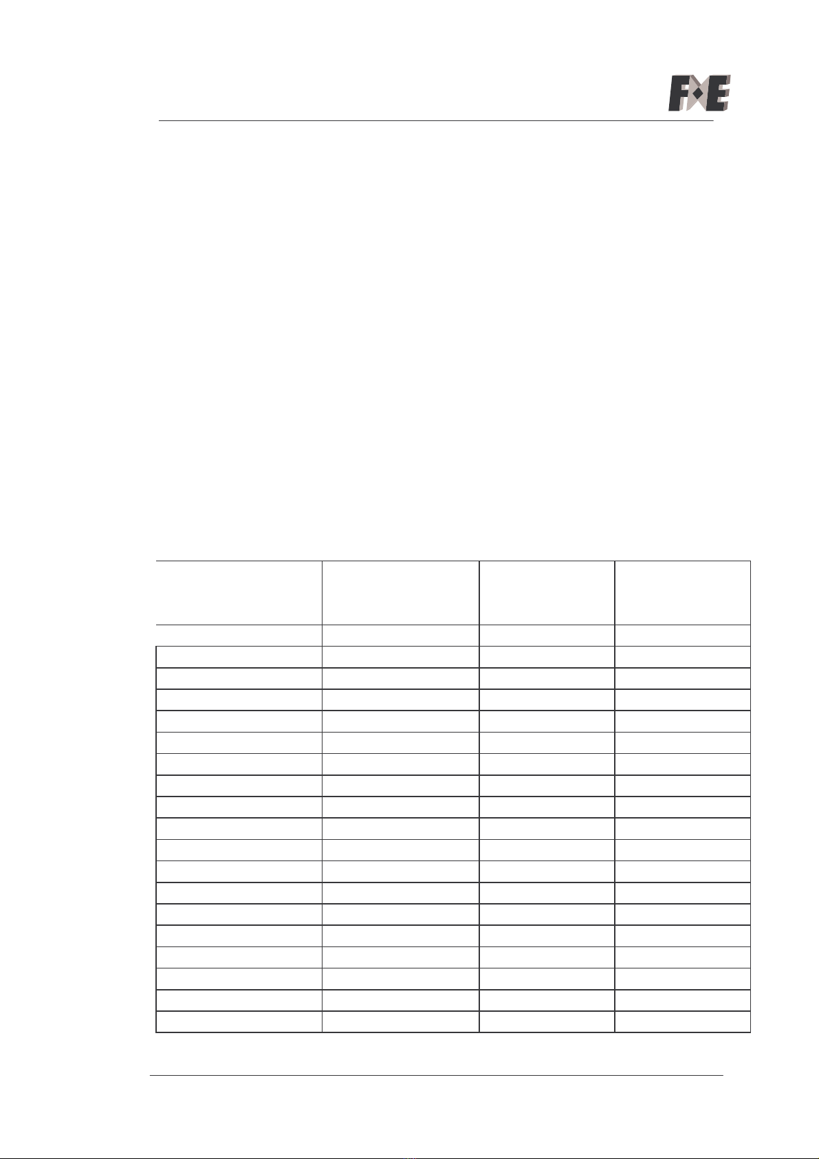
5 ATR833 Frequency-Channel Plan for combined 8.33 kHz /25
kHz Operation
The table below shows TX and RX operating frequency,
respective channel spacing and the corresponding displayed
frequency which is shown at the display of the ATR833 in the
range from 118.000 MHz to 118.100 MHz.
In combined 8.33 kHz / 25 kHz channel spacing mode, the
active channel name is displayed with 6 digits.
In "25 kHz only" channel spacing mode, frequencies are
displayed with 5 digits.
The ATR833 has two reception filters, one for 8.33 kHz and one
for 25 kHz channel spacing. In the 8.33/25 kHz Mode the two
filters are switched as shown in the table below, whereas in the
25 kHz Mode only the 25 kHz filter is used.
Of course this frequency-channel plan also applies to all other
frequencies between 118.100 MHz and 136.975 MHz.
Operating
frequency (MHz)
Channel
Spacing (kHz)
8.33/25 kHz Mode
displayed at
ATR833
25 kHz Mode
displayed at
ATR833
118.0000
25
118.00
0
118.00
118.0000 8.33 118.005
118.0083 8.33 118.010
118.0166 8.33 118.015
118.0250
25
118.025
118.02
118.0250 8.33 118.030
118.0333 8.33 118.035
118.0416 8.33 118.040
118.0500
25
118.050
118.05
118.0500 8.33 118.055
118.0583 8.33 118.060
118.0666 8.33 118.065
118.0750
25
118.075
118.07
118.0750 8.33 118.080
118.0833 8.33 118.085
118.0916 8.33 118.090
118.1000
25
118.100
118.10
118.1000 8.33 118.105
etc etc etc etc
Page: 17
6 Dimensions
SEL
M
O
D
E
SAVE
CHANGE
ON/OFF
V
O
L
[ 12 ]
TX
F
3
5
1

Page: 18
7 Approval
Table of contents
Other Filser Electronic Transceiver manuals


