filtemc FTSF2 Series User manual

Completed EMC Solution Provider
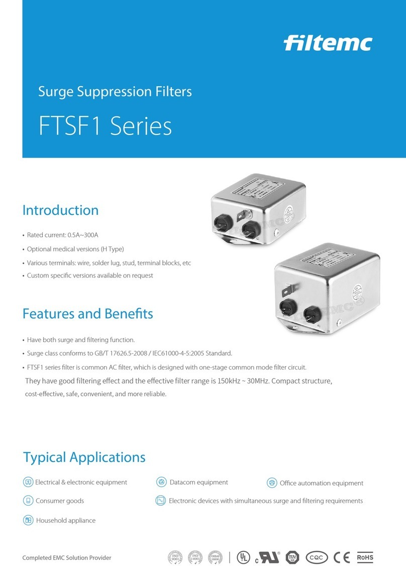
Surge Suppression Filters
FTSF2 Series
•Rated current: 0.5A~1600A
•Optional medical versions (H Type)
•Various terminals: wire, solder lug, stud, terminal blocks, etc
•Have both surge and ltering function.
Introduction
Features and Benets
•Surge class conforms to GB/T 17626.5-2008 / IEC61000-4-5:2005 Standard.
•FTSF2 series filter is high performance AC filter, which is designed with two-stage common mode filter circuit.
They have excellent common and differential mode filtering effect with filtering range from 10kHz to 30MHz.
•Custom specic versions available on request
Typical Applications
Electrical & electronic equipment
Electronic devices with simultaneous surge and ltering requirements
Consumer goods
Household appliance
Datacom equipment Oce automation equipment

Technical Data
Tabulates
Rated Voltage: VR
Operating Frequency: FR
Rated Current: IR
Test Voltage: Vtest
Climatic Category (IEC 60068-1)
110/250VAC
50/60Hz
0.5~1600A@40℃
300VDC, 3S(line-line); 2000VAC, 3S(line-ground)
25/085/21(-25℃/+85℃Damp heat test for 21 days)
Surge Suppression Filters
Professional EMI Filters Manufacturer
-L -W
FTSF2-3 3 < 0.6 --- ○ 95
FTSF2-6 6< 1.0 ---○ 170
FTSF2-10 10 < 1.0 ○
---
170
FTSF2-20 20 < 1.0 --- 320
○
Part No.
Rated
Current [A]
Leakage
Current [mA]
250VAC/50Hz
@20℃
Terminals
Weight [g]

Surge Suppression Filters
Completed EMC Solution Provider
Surge Test Results
Input voltage waveform (dierential mode2KV) Output voltage waveform (dierential mode1.3KV)
Input voltage waveform (common mode 4KV) Output voltage waveform (common mode1.3KV)
FTSF2-3 FTSF2-6
Insertion Loss (dB)
Common Mode
Differential Mode
Note: Insertion loss is
tested with a system
of empty load and 50
Ω-50Ω according to
UL1283 Standard. The
actual eect please
follow the eld data
of real application.
FILTEMC
R
FILTEMC
R
10K 100K 1M
100
80
60
40
20
0
30M
10M
Hz
dB

Surge Suppression Filters
FTSF2-10 FTSF2-20
Outline Drawing and Dimensions(mm)
Professional EMI Filters Manufacturer
FILTEMC
FILTEMC
R
R
100
80
60
40
20
0
30M
10M10K 100K 1M
FILTEMC
R
FILTEMC
R
FILTEMC
R
FTSF2-3
FTSF2-20
FILTEMC
R
34 MAX.
30 MAX.
71 MAX.
60±0.5
2- 4.5±0.5
20±0.5
9±0.5
19±0.5
20#BU
20#BN
20#YEGN
20#BU
20#BN
150 MIN. 150 MIN.
51±1
52 MAX.
30 MAX.86 MAX.
75±0.5
2- 5.0±0.5
25±0.5
22±0.5
10±0.5
86 MAX.
6.3*0.8±0.2
7.3±0.2
63±1
FTSF2-6/10
24±0.5
46 MAX.
87±0.5
98 MAX.
95±1
57 MAX.
2- 4.8±0.5
28.5±0.5
12.5±0.5
6.3*0.8±0.2
7.3±0.2
73±1
Hz
dB

Surge Suppression Filters
Professional EMI Filters Manufacturer
1. Storage of EMI Filters:
2. Installation of EMI Filters:
(Figure2) (Figure3)
(Figure1)
Important Notes on EMI Filter Application
EMI lters mustn't be left out in the heat of the sun or exposed
to the rain, it should be stored in warehouse with good
ventilation, surrounding temperature between -30℃and +65
℃, the highest relative air humidity lower than 90%, and no
corrosive liquid or gas.
• EMI lters should be installed at power input, and the line
inside the chassis be as short as possible to reduce radiated
interference.
• Both input and output lines of EMI lters neither be
intersected nor be tied up by string.
• Make sure the mounting ange fully grounded, and keep the
ground cable as short as possible if lters are connected to
other equipment.
• If the terminal is stud, please use two spanners to fasten the
screw nut when connecting to avoid stud rotating and thus
causing changes to the internal circuit and consequently
leading to lters arcing, short circuit, broken down or the
ltering eect worsened. First use spanner1 to x the screw nut
near the metal case, then use spanner2 to tighten the screw
nut in front( shown as Figure1), otherwise the terminals may be
damaged. Apply the same for the connection of other phases.
• Keep the tools fastening the stud be vertical to the metal
case of lter when installing terminal block lters
( shown as Figure2 ), must not tilt( shown as Figure3 ),
otherwise the terminal blocks may be damaged.

Surge Suppression Filters
3. Reminding and Warning:
Please read all the safety warnings and instructions before installing lters and putting them into use:
• Don't take terminals as supporting point when moving lters to avoid the terminals distortion,
loosening or broken.
• The protective earth connections shall be the rst to be made when the EMC lter is installed and
the last to be disconnected.
• Filters generate leakage current, please make sure they are well grounded before putting into
operation.
• If the rated current is higher than 50A, we recommend grounding by the earth terminals but not
only through the metal case of lters.
• Danger of electric shock: EMC lters contain components that store an electric charge. Dangerous
voltages can continue to exist at the lter terminals for longer than ve minutes even after the power
has been switched o.
• The working conditions of EMI lter should comply with the technical parameters stated on the
label, over voltage or overload could cause damage to lters. It is suggested to take proper over
current protection measures.
• Current drop occurs when the surrounding temperature rises, fail to follow the current drop
requirement may lead to impermissible exceeding of the component temperature, as a result the
service life of lters will be shortened after long time running.
Service and Support
Contact information of Tech. Dept.:
T: 0086-531-58622887
F: 0086-531-58622899
E: ltemc@ltemc.com
A: Building 20, Xinmao Qilu Science and
Technology City, No. 1 Zidong Road,
Tianqiao District, Jinan 250119, China
Contact information of Sales:
T: 0086-531-58622888
F: 0086-531-58622886
E: lter@ltemc.com
Skype: [email protected]
Web.: www.ltemc.com
This manual suits for next models
4
Table of contents
Other filtemc Surge Protector manuals