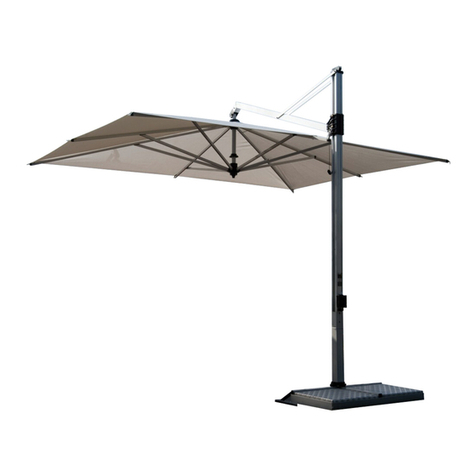
FIM FLEXY Operating instructions

WB
Before
starting,
check
out
the
FIM
Flexy
Setup
Video
at
www.fim-umbrella.com/instructions.htm

FLEXY
INSTRUCTIONS FOR ASSEMBLY AND
RECOMMENDATIONS FOR USE
READ THIS HANDBOOK IMMEDIATELY
These instructions have to be handed over to the end-user of the product who has to read and keep them.
These instructions are provided for an easy set-up of your FLEXY and for your safety. It is essential that the given
instructions are followed carefully.
Failure to do so may result in injury to people or damage to materials. If in doubt always contact a technical expert.
This symbol indicates very important information. Strictly follow instructions accompanied by this symbol. This
does not mean that the other information contained in this handbook is not important.
Keep this handbook for future reference.
APPLIES TO ALL IN THIS SECTION
Please read and follow all the instruction. Only one manual is supplied for all the possible combinations of the
FLEXY.
Damage or injuries may result if the FLEXY is not assembled and used as described in the
instruction.
For safe use it is essential that anyone using the FLEXY read all the instruction in advance.
Only persons familiar with the safety aspects of the FLEXY should operate the
FLEXY.
The FLEXY principally is a protection from the sun, not a protection against weather. It
must be closed in presence of strong winds or thunderstorms, as well as heavy rain or snow
(danger of water pooling on the cover).
Always close the FLEXY
Each base must be weighed down with a minimum weight of
550 lbs

(Fig. 1) Cover contained in one carton composed of the following parts: sliding canopy A, , 2 long crossbars C,
2 short crossbars D, castings R and R' with a handwheel S, an Allen key W.
(Fig. 2A): Cantilever pole F, cantilever pole G,
(Fig. 2B) Pair of upright poles E, screws e and an Allen key e fixed on the poles.
(Fig. 2C) Opening rod I
(Fig. 3)2 bases contained in two cartons composed of the following parts: base L for floor slabs 2 stabilizers M
and a hardware bag H
1. Take out the content of the bag of hardware (H).
2. (Fig.4) fix the stabilizers M and the upright pole (E) to the base (L).
.
CAUTION: tighten the bolts well.
3. (Fig. 5) the bases (L) at the correct distance the
he
CAUTION: make sure that the bases are perfectly aligned, horizontal and on the same level on the ground.
For installation the orientation
indicated on the drawing .
4. (Fig.4A) lace in each base as shown in the picture.
5. (Fig.5A) Join upright poles E with the cantil ver poles F e G. To join upright and cantil ver poles unscrew the screws e on
both sides of the upright poles E, insert the cantilever poles and fix the screws e with an Allen key e.
6. Put additional weight on each base until the minimum weight of 550 lbs is reached. As an example
pots of adequate size, filled with sand or gravel, may be used
1. (Fig. 6) Unscrew 4 screws Q and join 2 crossbars C with 2 crossbars D and screw the 4 screws Q.
2. (Fig. 7) Align the sliders P and P as shown in the picture.
Align the crossbars C+D with the screws Q facing upwards.
3. (Fig. 8) Insert the crossbars into the sliders P e P
4 (Fig.9) Join the casting R to the crossbars C+D and fix the screws Y with the Allen key W. Remove the hand wheel S,
the washer s from the casting R but dont remove the spring r.
5 (Fig. 9A) Join the casting R to the crossbars C+D and fix
the screws Y with the Allen key W. Remove the hand wheel S, the washer s from the casting R but dont remove the
spring r.
6 After the above you can mount the sliding canopy on the poles, for details please see the next
CAUTION: To avoid damage the operation has to be done simultaneously by two persons with 2 step ladders.
1. (Fig. 10) Raise the sliding canopy. Make sure that on the castings R-R the spring r is installed according to the Fig.
10A.
2. (Fig. 10A) Join 2 castings R R to the poles and screw on the hand wheel S putting the washer s between S and the
castings on the poles.
3. (Fig.9) Push 2 sliders P' against the casting R. Fix 2 sliders P so that the stem of 2 hand wheels J into the holes
of the crossbars C+D.
4. (Fig.12- Fig.12A 12B) unscrew the handwheel r from the casting R . Pull the belt support V and insert it in the casting R
and lock it replacing the handwheel r. Important: make sure that the belt is not tangled
5. (Fig.11) The Flexy is now ready to be used.

1. (Fig.13) To operate the Flexy insert the Opening rod I in the opening mechanism XX
2. To tilt the canopy follow these steps:
(Fig.14A - 14) Loosen the hand wheel S on both sides. The teeth of the casting must be fully separated allow free
movement of the top.. Re-tighten both handwheels S, making sure that the the teeth of both castings are fully engaged.
1. Close the sliding canopy A completely.
2. Put the protect cover and it with the .
CAUTION: always close the TENDASOL FLEXY in presence of strong winds or
thunder storms, as well as heavy rain (danger of waterpockets on the cover) whenever it is not under .
1. To apply lateral valances, rib .
2.
3. The frontal valances are fixed to the ribs by buttons .
1. Remove screws from both sides of the ribs.
Push the end of the panel outward removing it completely from the ribs.
2. To re-install the panel insert into the ribs. Take the panel with both hands and slide
it .
3. Insert the screw .
The can be cleaned by hand with a smooth cloth, lukewarm water (about 30°C 85°F) and a common detergent for delicate
fabrics. After extensive rinsing the material has to be dried. To extend the life span of the fabric, it is advisable not to perform
this operation in the bright sun.
For washing in industrial washing machines, take the off the structure have washed with a mild detergent, delicate
program, extensive rinsing and water temperature not exceeding 40°C ( 110°F). Have air (do not tumble dry!) and
do not iron.
To extend the life span of the product, it is advisable to disassemble and store the awning away in a dry place at the end of the
season. Before sto ing your FLEXY away, clean the structure with a damp cloth and dry it. For the cleaning of the
cover see the preceeding paragraph.
CAUTION: Check the integrity of all components. Should any part be damaged contact the dealer where it was
purchased and order the required spare parts.
Touch up any possibly chipped paint. Lightly lubricate all moving parts with silicon spray.
Important

Freestanding
Base
design
differs slightly for the
North American
market. Please refer
to the instructions
included in the base carton


Other FIM Patio Furniture manuals


