Fimap Disinfector User manual

ORIGINAL INSTRUCTION DOC. 10098188 - Ver. AA - 07-2020
PROFESSIONAL SANITIZATION MACHINES
USE AND MAINTENANCE MANUAL
DISINFECTOR


CONTENTS
CONTENTS...................................................................................................................................3
LOCATION OF THE MAIN MACHINE COMPONENTS ...............................................................4
GENERAL SAFETY REGULATIONS ...........................................................................................4
GENERAL DESCRIPTION ...........................................................................................................5
TECHNICAL DESCRIPTION.................................................................................................................................... 5
LABELS USED ON THE DISINFECTOR KIT ..............................................................................5
PREPARATION OF MACHINE .....................................................................................................5
FILLING THE SOLUTION TANK WITH WATER ...................................................................................................... 5
SANITIZING SOLUTION .......................................................................................................................................... 5
PREPARING TO WORK ...............................................................................................................6
STARTING WORK ........................................................................................................................7
ADDITIONAL FUNCTIONS ..........................................................................................................8
TEMPORARY DEACTIVATION OF DELIVERY OF SANITIZING PRODUCT ......................................................... 8
SPRAY GUN KIT ...................................................................................................................................................... 8
AT THE END OF THE WORK.......................................................................................................8
ROUTINE MAINTENANCE...........................................................................................................9
CLEANING THE WATER SYSTEM FILTER ............................................................................................................ 9
ADJUSTMENT INTERVENTIONS................................................................................................9
ADJUSTING THE DIRECTION OF THE UPPER NOZZLES ................................................................................... 9
TROUBLESHOOTING ................................................................................................................10
3

LOCATION OF THE MAIN MACHINE COMPONENTS
The main components of the disinfector kit are:
1. Lower nozzles.
2. Spray gun control switch.
3. Valve to control ow to the upper left nozzles.
4. Valve to control ow to the upper right nozzles.
5. Upper nozzle support rotation adjustment knob.
6. Control switch for upper nozzles.
7. Control switch for lower nozzles.
8. Upper nozzles.
Before using the machine, please carefully read and follow the instructions in the USE AND
MAINTENANCE document supplied with the machine, in addition to the instructions in the
following document.
ATTENTION:
• This machine should not be used by persons (including children) with physical, sensorial
or mental impairments and by persons with little experience and/or little knowledge of the
machine itself.
• Children must be supervised to ensure they do not play with the machine.
• The nebulized product must never be directed towards equipment containing electrical
components.
• When working, do not point the vaporised jet towards your face or in the direction of people
nearby.
• The spray gun must not be used if it has been dropped or if there are any visible signs of
damage.
• Before starting to work check that there are no leaks.
• The cleaning and maintenance to be carried out by the user must not be performed by
unsupervised children.
• Keep the machine out of reach of children when it is connected to the power.
GENERAL SAFETY REGULATIONS
4
2
36
47
5
5
1
8

GENERAL DESCRIPTION
TECHNICAL DESCRIPTION
The Disinfector kit is a device designed for the sanitization of oors which sprays special sanitizing products in areas with heavy footfall,
thus reducing the presence of pathogenic material as it moves forwards. The machine with the disinfector kit must only be used for this
purpose.
LABELS USED ON THE DISINFECTOR KIT
Symbol showing the location of the control switch for the upper nozzles:
It is used on the machine to indicate the switch that controls the activation of the upper spray nozzles.
Symbol showing the location of the control switch for the lower nozzles:
It is used on the machine to indicate the switch that controls the activation of the lower spray nozzles.
Warning labels on the use and storage of the machine:
Used on the machine to indicate warnings regarding how to use the machine correctly.
PREPARATION OF MACHINE
FILLING THE SOLUTION TANK WITH WATER
Before lling the solution tank, carry out the following steps:
1. Take the machine to the usual place for lling the solution tank.
2. Carry out the steps to secure the machine, see paragraph SECURING THE MACHINE in the machine's use and maintenance manual.
3. Carry out the steps to ll the solution tank with water, see paragraph FILLING THE SOLUTION TANK WITH WATER, in the machine's use
and maintenance manual.
SANITIZING SOLUTION
For BMg machines with a 3 litre tank, after lling the solution tank with clean water, proceed as follows:
1. Carry out the steps to secure the machine, see paragraph SECURING THE MACHINE in the machine's use and maintenance manual.
2. Press the recovery tank release lever (1) and turn the recovery tank into the maintenance position (Fig. 1).
3. Disconnect the male insert (2) from the female insert (3) on the cap of the detergent canister (Fig.2).
N.B.: before pulling on the male insert, push the lever in the female insert.
4. Grip the handle on the detergent canister (4) to remove it from the compartment in the solution tank (Fig.3).
5. Unscrew the cap (5) of the detergent canister (Fig.4).
6. Fill the tank with the sanitizing chemical product in the concentration and manner indicated on the label by the manufacturer of the sanitizing
product.
CAUTION: It is recommended to wear the appropriate PPE (Personal Protective Equipment), suitable for the work to be carried out.
5
1
7 8
1
9 10
2 5
3 6
4 8
3 7
2 6
4
5
9
11

7. Close the cap correctly to prevent liquid leaking out when working.
8. Grip the canister handle to replace the canister in its compartment inside the solution tank.
9. Connect the male insert to the female insert in the cap of the detergent canister.
10. Rotate the recovery tank into the work position. Make sure that the recovery tank retainer system is correctly engaged.
For BMg machines with a 10 litre tank, after lling the solution tank with clean water, proceed as follows:
1. Disconnect the male insert (6) from the female insert (7) on the cap of the detergent canister (Fig.5).
N.B.: before pulling on the male insert, push the lever in the female insert.
2. Grip the handle on the detergent canister (8) to remove it from the compartment in the front of the machine (Fig.6).
3. Unscrew the cap (9) of the detergent canister (Fig.7).
4. Fill the tank with the sanitizing chemical product in the concentration and manner indicated on the label by the manufacturer of the sanitizing
product.
CAUTION: It is recommended to wear the appropriate PPE (Personal Protective Equipment), suitable for the work to be carried out.
5. Close the cap correctly to prevent liquid leaking out when working.
6. Grip the canister handle to replace the canister in its compartment in the front of the machine.
7. Connect the male insert to the female insert in the cap of the detergent canister.
For BMg machines with a 20 litre tank, after lling the solution tank with clean water, proceed as follows:
1. Unscrew the cap (10) of the detergent canister (Fig.8).
2. Fill the tank with the sanitizing chemical product in the concentration and manner indicated on the label by the manufacturer of the sanitizing
product.
CAUTION: It is recommended to wear the appropriate PPE (Personal Protective Equipment), suitable for the work to be carried out.
3. Close the cap correctly to prevent liquid leaking out when working.
For MMg and Magna machines, ll the solution tank with clean water and then proceed as follows:
1. Unscrew the cap (11) that can be found by the steering column (Fig.9).
2. Fill the tank with the sanitizing chemical product in the concentration and manner indicated on the label by the manufacturer of the sanitizing
product.
CAUTION: It is recommended to wear the appropriate PPE (Personal Protective Equipment), suitable for the work to be carried out.
3. Close the cap correctly to prevent liquid leaking out when working.
Before beginning to sanitize, it is necessary to:
1. Check that the quantity of sanitizing solution in the solution tank is correct for the type of work to be carried out; if not, rell the solution tank.
See paragraph FILLING THE SOLUTION TANK WITH WATER, in the machine's use and maintenance manual, as well as the paragraph
“SANITIZING SOLUTION” on page 5.
2. Check that the main machine switch is in position "0", turn the key a quarter turn counter-clockwise. With the machine o, remove the key
from the instrument panel.
3. Connect the battery connector to the main system connector on the machine; the two connectors are located inside the machine, in the
battery compartment.
WARNING: It is recommended that all installation and maintenance operations be carried out by expert personnel, trained at the
specialised assistance centre.
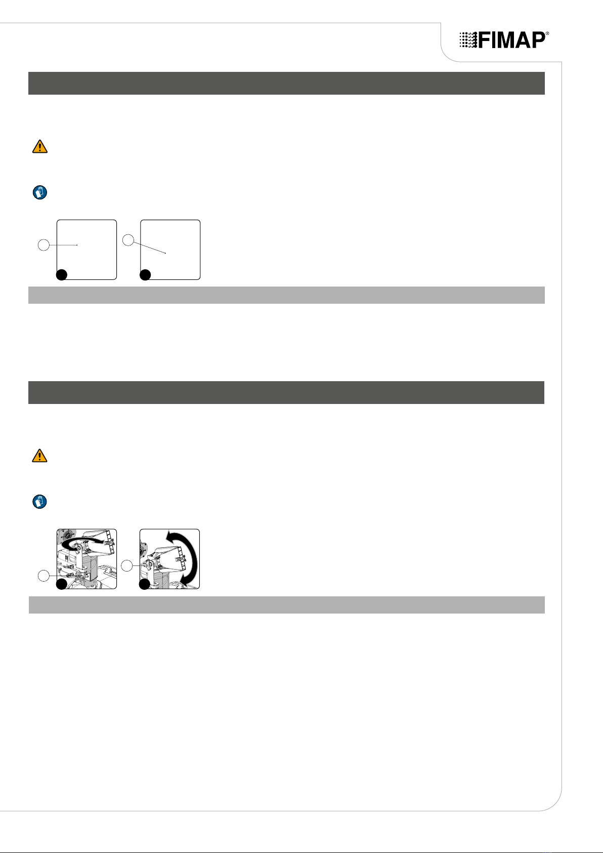
4. Move to the right rear part of the machine and check that the electro-brake, present in the traction gear motor, is engaged; turn the lever
clockwise.
5. Move to the front of the machine and check that the water system lter cap is closed, otherwise tighten it.
PREPARING TO WORK
6

STARTING WORK
To start working, proceed as follows:
1. Carry out all the checks listed in the chapter “PREPARING TO WORK” on page 6.
2. Sit on the driver’s seat.
3. Insert the key into the main switch on the control panel. Turn the main machine switch to "", turn the key a quarter turn clockwise.
4. Open the ow of sanitizing solution, using the valve adjustment knob on the rear left side of the steering column.
N.B.: To open the ow of sanitizing solution fully, move the knob upwards as far as it will go.
5. Activate the spray function of the sanitizing product.
N.B.: If you only wish to spray the sanitizing product from the lower nozzles, press the switch (1) on the steering column. (Fig.1).
N.B.: If you only wish to spray the sanitizing product from the upper nozzles, press the switch (2) on the steering column. (Fig.1).
N.B.: If you want to spray the sanitizing product from the upper and lower nozzles, press both switches (1) and (2) on the steering
column. (Fig.1).
N.B.: if the LED on the switch is on, the spraying system is active; if the LED is o, the system is deactivated.
N.B.: if you want to deactivate the spraying system, press the switch again.
6. When the drive pedal is pressed, the machine will start to move and spray the sanitizing product.
N.B.: The sanitizing product is only dispensed when a certain speed is reached; below this speed, the disinfector kit will not be activated.
The machine will now begin to work with full eciency until the battery is at or until the sanitizing solution is used up.
N.B.: If you the drive pedal is released during work, the machine will start to slow down and the sanitizing product pump will stop delivering
the product into the machine's water circuit. The two motors present on the upper nozzles will remain in operation for a few seconds when
the drive pedal is released to allow the compressed air to expel the sanitizing product present in the machine's water circuit.
WARNING: When working, do not point the vaporised jet towards electrical components or in the direction of people nearby.
7
1 2
2
1

SPRAY GUN KIT
On request, the machine can be equipped with the spray gun kit. To use this, proceed as follows:
1. Stop the machine.
2. Get o the machine and go to the rear of it.
3. Release the spray gun accessory (at the back of the machine) from the retainers.
4. Activate the optional spray gun kit by pressing the switch (3) on the back of the machine (Fig.3).
N.B.: As soon as the switch (3) is pressed, the LED on it comes on.
CAUTION: It is recommended to wear the appropriate PPE (Personal Protective Equipment), suitable for the work to be carried out.
WARNING: When working, do not point the vaporised jet towards electrical components, your own face or in the direction of people
nearby.
N.B.: Before activating the spray gun kit, check that the quantity of sanitizing solution is suitable for the work to be carried out.
5. Activate the solution jet by pressing the lever on the spray gun accessory.
ADDITIONAL FUNCTIONS
TEMPORARY DEACTIVATION OF DELIVERY OF SANITIZING PRODUCT
At the rear of the machine, there are two valves that control the ow of sanitizing solution to the upper nozzles; to prevent on of the two nozzles
from working, proceed as follows:
1. Stop the machine.
2. Get o the machine and go to the rear of it.
3. Turn the lever on the valve (1) clockwise if you want to block the supply of sanitizing solution from the right nozzle (Fig.1).
4. Turn the lever on the valve (2) clockwise if you want to block the supply of sanitizing solution from the left nozzle (Fig.2).
N.B.: Only the delivery of sanitizing solution will be blocked; the fan present in the nozzle will continue to work.
5. Sit in the driver’s seat and resume work.
AT THE END OF THE WORK
At the end of the work, and before carrying out any type of maintenance, perform the following operations:
1. Turn o the sanitizing product spray function by pressing the switch on the steering column.
N.B.: if the LED on the switch is on, this means that the spraying system is active; if the LED is o, the system is deactivated.
2. Take the machine to the designated maintenance area.
WARNING: The place designated for this operation must comply with current regulations concerning safety at work and current
environmental protection regulations.
3. Turn the machine o; turn the main machine switch to "0", turn the key a quarter turn counter-clockwise. Remove the key from the
instrument panel.
4. Carry out all the procedures listed in the chapter “ROUTINE MAINTENANCE” on page 9.
5. Once the maintenance operations are complete, take the machine to the designated storage location.
ATTENTION: Park the machine in an enclosed place, on a at surface; near the machine there must be no objects that could either
damage it, or be damaged through contact with it.
6. Make sure the machine is secured; see paragraph SECURING THE MACHINE in the machine's use and maintenance manual.
8
1 2 2
2 2
1

ROUTINE MAINTENANCE
Before carrying out any routine maintenance operations, proceed as follows:
1. Take the machine to the maintenance area.
WARNING: the place designated for this operation must comply with current regulations concerning safety at work and current
environmental protection regulations.
2. Carry out the steps to secure the machine, see paragraph SECURING THE MACHINE in the machine's use and maintenance manual.
ATTENTION: It is recommended to wear the appropriate PPE (Personal Protective Equipment), suitable for the work to be carried out.
CLEANING THE WATER SYSTEM FILTER
In order to clean the water system's lter, do the following:
1. Close the tap's output ow, and shift the knob (1) on the left hand side of the steering column (Fig.1) downward.
2. Remove the sanitizing solution lter cap (2) (Fig.2).
3. Rinse the lter cartridge under a jet of water, and use a brush to eliminate any impurities, if necessary.
4. Once the lter cartridge is clean, repeat the operations in the opposite order to reassemble all the parts.
ADJUSTMENT INTERVENTIONS
Before carrying out any adjustments, proceed as follows:
1. Take the machine to the maintenance area.
WARNING: the place designated for this operation must comply with current regulations concerning safety at work and current
environmental protection regulations.
2. Carry out the steps to secure the machine, see paragraph SECURING THE MACHINE in the machine's use and maintenance manual.
ATTENTION: It is recommended to wear the appropriate PPE (Personal Protective Equipment), suitable for the work to be carried out.
ADJUSTING THE DIRECTION OF THE UPPER NOZZLES
To adjust the direction of the upper nozzles, proceed as follows:
1. Stand at the back of the machine.
2. Loosen the knob (1) and turn the conveyor support. (Fig.1).
3. Once you have found the correct position, tighten the knob (1).
4. Loosen the knob (2) and turn the conveyor. (Fig.2).
5. Once you have found the correct position, tighten the knob (2).
9
2
1
12
2
1
1
2

TROUBLESHOOTING
This chapter lists the most common problems linked with the use of the machine. If you are unable to resolve the problems with the information
given here, please contact your nearest assistance centre.
PROBLEM POSSIBLE CAUSE SOLUTION
SANITIZING
SOLUTION SPRAY
NOT SUFFICIENT
The quantity of sanitizing solution in the
water system is not sucient for the work
to be carried out.
Check that the amount of sanitizing solution present in the machine water
system is sucient for the work to be carried out; if this is not the case,
top it up. See paragraph FILLING THE SOLUTION TANK WITH WATER,
in the machine's use and maintenance manual, as well as the paragraph
“SANITIZING SOLUTION” on page 5.
Sanitizing solution lter clogged. Check that the sanitizing solution lter is not clogged; if it is, clean it. See
paragraph “CLEANING THE WATER SYSTEM FILTER” on page 9.
10


FIMAP S.p.A.
Via Invalidi del Lavoro, 1
37059 S. Maria di Zevio - Verona - Italy
Tel. 0039 045 6060497 - Fax 0039 045 6060440
E-mail: service@map.com Web: www.map.com
Table of contents
Popular Accessories manuals by other brands

Honeywell
Honeywell RCW110 installation instructions

iWorX
iWorX TS300 Series installation guide

Edirol
Edirol EDIROL FA-101 owner's manual

Pro-Ject Audio Systems
Pro-Ject Audio Systems Measure It Instructions for use

Pfeiffer Vacuum
Pfeiffer Vacuum CCR 371 operating instructions

YDLIDAR
YDLIDAR X2 user manual