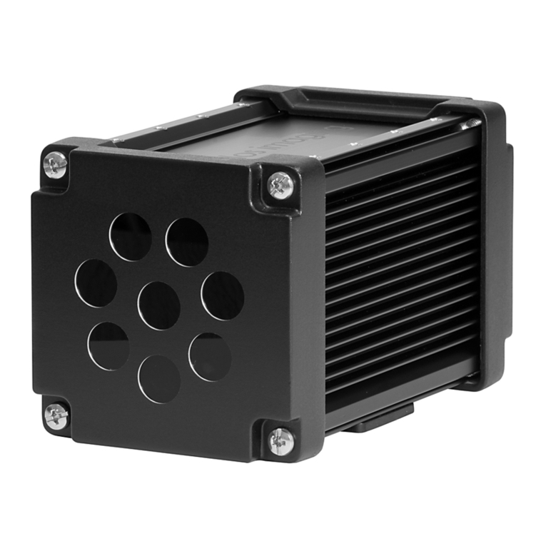
Hans Turck DR15S-IOL8X2 Series User manual

Your Global Automation Partner
IO-Link Parameters – IO-Link Version 1.1
DR15S-…-IOL8X2…
Radar Distance Sensors

2Hans Turck GmbH & Co. KG | T +49 208 4952-0 | F +49 208 4952-264 | [email protected] | www.turck.com

V01.00 | 2021/10 3
Contents
1 About This Manual ..........................................................................................................................5
1.1 Target groups................................................................................................................ 5
1.2 Explanation of symbols used ..................................................................................... 5
1.3 Other documents ......................................................................................................... 5
1.4 Feedback about these instructions........................................................................... 5
2 Notes on the Product...................................................................................................................... 6
2.1 Product identification.................................................................................................. 6
2.2 Turck service.................................................................................................................. 6
3 Software-Supported IO-Link Parameterization......................................................................... 7
4 IO-Link Parameters.......................................................................................................................... 8
4.1 General parameters .....................................................................................................8
4.2 Process input data........................................................................................................ 9
4.3 Standard parameters.................................................................................................10
4.4 Parameters...................................................................................................................12
4.5 Events ...........................................................................................................................20
5 Turck Subsidiaries - Contact Information .................................................................................21

Contents
4Hans Turck GmbH & Co. KG | T +49 208 4952-0 | F +49 208 4952-264 | [email protected] | www.turck.com

V01.00 | 2021/10 5
1 About This Manual
This manual describes the parameterization of devices using IO-Link. The manual contains gen-
eral information on IO-Link and a list of the available parameters.
1.1 Target groups
These instructions are aimed at qualified personal and must be carefully read by anyone
mounting, commissioning, operating, maintaining, dismantling or disposing of the device.
1.2 Explanation of symbols used
The following symbols are used in these instructions:
DANGER
DANGER indicates a dangerous situation with high risk of death or severe injury if
not avoided.
WARNING
WARNING indicates a dangerous situation with medium risk of death or severe in-
jury if not avoided.
CAUTION
CAUTION indicates a dangerous situation of medium risk which may result in minor
or moderate injury if not avoided.
NOTICE
NOTICE indicates a situation which may lead to property damage if not avoided.
NOTE
NOTE indicates tips, recommendations and useful information on specific actions
and facts. The notes simplify your work and help you to avoid additional work.
uCALL TO ACTION
This symbol denotes actions that the user must carry out.
aRESULTS OF ACTION
This symbol denotes relevant results of actions.
1.3 Other documents
Besides this document the following material can be found on the Internet at www.turck.com:
nData sheet
nQuick Start Guide
nInstructions for use
1.4 Feedback about these instructions
We make every effort to ensure that these instructions are as informative and as clear as pos-
sible. If you have any suggestions for improving the design or if some information is missing in
the document, please send your suggestions to [email protected].

Notes on the Product
6Hans Turck GmbH & Co. KG | T +49 208 4952-0 | F +49 208 4952-264 | [email protected] | www.turck.com
2 Notes on the Product
2.1 Product identification
These instructions apply to the following radar distance sensors:
DR 15 S – M30 E – IOL 8 X2 – H1 1 4 1
DR 15 S Series –
Aperture angle, radar wave
S7°
Sensing range
…Max. range in m
Functional principle
DR Radar, Distance
M30 E Design –
Housing length
ELong
Housing
M… Threaded barrel, stain-
less steel
Ø in [mm]
IOL 8 X2 Electrical version –
Indication
X2 Multicolor LED
Voltage range
817…33 VDC
Output function
2UPN Switching outputs
IOL IO-Link
H1 1 4 1 Electrical connection:
Connector
Assignment
1Standard assignment
Number of contacts
44 contacts
Connector type
1Straight
Connector type
H1 M12 × 1 connector
2.2 Turck service
Turck supports you with your projects, from initial analysis to the commissioning of your applic-
ation. The Turck product database under www.turck.com contains software tools for program-
ming, configuration or commissioning, data sheets and CAD files in numerous export formats.
The contact details of Turck subsidiaries worldwide can be found on p. [}21].

V01.00 | 2021/10 7
3 Software-Supported IO-Link Parameterization
The ports of the IO-Link master can be configured in IO-Link mode (IOL) or in standard IO mode
(SIO).
If a port is configured in SIO mode, the IO-Link master behaves at this port like a normal digital
input. The connected IO-Link device transfers its conventional switching output to the IO-Link
master – there is no communication between the device and the master.
If a port is configured in IOL mode, the IO-Link master tries to wake up the connected IO-Link
device via the "Wake-up Request". If the master receives a response from the IO-Link device,
both devices start to communicate with each other. The communication parameters are ex-
changed first of all; the cyclic data exchange of the process data (process data objects) then
starts.
When IO-Link communication (IOL mode) is active, both a cyclic and acyclic communication
service is available.
There are two ways of setting the parameters via IO-Link:
nvia on-request data objects (e.g. close to the PLC via the IO-Link function block)
nvia tool-based engineering using FDT/DTM (e.g. PACTware with the use of DTM or the IODD
or the web demo and Turck configuration tool)
Device parameters (on-request data objects)
Device parameters are exchanged acyclically and on request of the IO-Link master. The IO-Link
master always sends a request to the device first, then the device responds. This applies when
the data is written into the device and also when data is read from the device. On-request data
objects (ORDO) enable parameter values to be written into the device (write) or device states to
be read from the device (read).
IO-Link configuration in PROFINET
SIDI (Simple IO-Link Device Integration) enables IO-Link devices in PROFINET applications to be
configured directly in the programming environment (e.g. TIA Portal). The Turck IO-Link devices
are integrated in the GSDML file of the TBEN, TBPN and FEN20 series IO-Link masters and can be
set in the programming environment as submodules of a modular I/O system. The user has
access here to all device properties and parameters.

IO-Link Parameters
8Hans Turck GmbH & Co. KG | T +49 208 4952-0 | F +49 208 4952-264 | [email protected] | www.turck.com
4 IO-Link Parameters
4.1 General parameters
Parameter Content
Vendor ID 317 (0x13D)
Device ID 557072 (0x88010)
IO-Link version 1.1
Bitrate COM2 (38.4 kbit/s)
Minimum cycle time 5 ms
SIO supported True
M-Sequence Capability PREOPERATE = TYPE_1_2 with 2 octets on-request data
OPERATE = TYPE_2_V with 8 octets on-request data
ISDU supported
Block Parameter True
Data Storage True
ProfileCharacteristic 0x000B: SSP 3.2, includes 0x800B
0x4000: Identification and diagnosis, includes 0x8000, 0x8002, 0x8003, 0x8100
0x800D: Switching signal channel
0x8001: Binary data channel
0x8004: Teach channel
0x8007: Teach-in single value
0x8101: Locator

V01.00 | 2021/10 9
4.2 Process input data
The internal process data is output in 0.1mm increments. The conversion is carried out
according to the unit.
Process value in millimeters = ProcessDataIn×0.1
Process value in meters = ProcessDataIn×0.001
Process value in inches = ProcessDataIn×0.003937008
Process value in feet = ProcessDataIn×0.000328084
Process value in yards = ProcessDataIn×0.0001093613
The internal process data must be multiplied by a factor of 0.1 for the signal strength.
Signal strength in % = SignalStrength×0.1
Name Byte.Bit-Offset Bit length Subindex access
supported
Data Type Value Description
Switching state of
output 1
5.0 1 False Boolean False/true
False Off
True On
Switching state of
output 2
5.1 1 False Boolean False/true
False Off
True On
Scaling exponent 4.0 8 False Integer
Process data 0.0 32 False Integer -2147483640…
+2147483644
-2147483640 Out of range (-)
2147483640 Out of range (+)
2147483644 No measure-
ment data

IO-Link Parameters
10 Hans Turck GmbH & Co. KG | T +49 208 4952-0 | F +49 208 4952-264 | [email protected] | www.turck.com
4.3 Standard parameters
Name Index
(dec.)
Index
(hex.)
Sub-
index
(dec.)
Sub-
index
(hex.)
Subindex
access
supported
Access Byte.
Bit-
Offset
Bit
length
Data Type Value Default Description
Min Cycle
Time
0 0x0 3 0x3 True Read 2.0 8 UInteger
IO-Link
Version ID
0 0x0 5 0x5 True Read 4.0 8 UInteger 17
Vendor ID 1 0 0x0 8 0x8 True Read 7.0 8 UInteger
Vendor ID 2 0 0x0 9 0x9 True Read 8.0 8 UInteger
Device ID 1 0 0x0 10 0xA True Read 9.0 8 UInteger
Device ID 2 0 0x0 11 0xB True Read 10.0 8 UInteger
Device ID 3 0 0x0 12 0xC True Read 11.0 8 UInteger
Standard
Command
2 0x2 0 0x0 True Write 0.0 8 UInteger 0…
255
System
command
65 Teach far
point
66 Teach near
point
126 Start blinking
127 Stop blinking
128 Device reset
129 Application
reset
130 Restore fact-
ory settings
160 Reset largest
distance value
161 Reset smallest
distance value
Parameter
(write) Access
Lock
12 0xC 1 0x1 False Read/
write
0.0 1 Boolean False/
true
Device access
locks
Data Storage
Lock
12 0xC 2 0x2 False Read/
write
0.1 1 Boolean False/
true
Device access
locks
Local Para-
meterization
Lock
12 0xC 3 0x3 False Read/
write
0.2 1 Boolean False/
true
Device access
locks
Local User
Interface
Lock
12 0xC 4 0x4 False Read/
write
0.3 1 Boolean False/
true
Device access
locks
Vendor Name 16 0x10 0 0x0 True Read 0.0 512 String Turck Vendor name
Vendor Text 17 0x11 0 0x0 True Read 0.0 512 String www.
turck.
com
Additional
manufacturer
information

V01.00 | 2021/10 11
Name Index
(dec.)
Index
(hex.)
Sub-
index
(dec.)
Sub-
index
(hex.)
Subindex
access
supported
Access Byte.
Bit-
Offset
Bit
length
Data Type Value Default Description
Product Name 18 0x12 0 0x0 True Read 0.0 512 String DR…-
M30E-
…8X2-
H1141
Manufacturer's
device
designation
Product ID 19 0x13 0 0x0 True Read 0.0 512 String ID
Product Text 20 0x14 0 0x0 True Read 0.0 512 String Radar
dis-
tance
sensor
Device
category
Serial Number 21 0x15 0 0x0 True Read 0.0 128 String Device serial
number
Hardware
Version
22 0x16 0 0x0 True Read 0.0 512 String Hardware
revision
Firmware
Version
23 0x17 0 0x0 True Read 0.0 512 String Firmware
revision
Application
Specific Tag
24 0x18 0 0x0 True Read/
write
0.0 256 String *** Any user
generated
content
Error Count 32 0x20 0 0x0 True Read 0.0 16 UInteger
Device Status 36 0x24 0 0x0 True Read 0.0 8 UInteger 0…
255
0 Device is OK
1 Maintenance
required
2 Out of
specification
3 Functional
check
4 Failure
Detailed
Device Status
37 0x25 0 0x0 False Read 0.0 88 Array
Process Data
Input
40 0x28 0 0x0 True Read 0.0 48 Process-
DataIn
Union

IO-Link Parameters
12 Hans Turck GmbH & Co. KG | T +49 208 4952-0 | F +49 208 4952-264 | [email protected] | www.turck.com
4.4 Parameters
Name Index
(dec.)
Index
(hex.)
Sub-
index
(dec.)
Sub-
index
(hex.)
Subindex
access
supported
Access Byte.
Bit
Offset
Bit
length
Data Type Value Default Description
Function
specific tag
25 0x19 0 0x0 True Read/
write
0.0 256 String NaN…
NaN
*** User text to
describe
function
Location
specific tag
26 0x1A 0 0x0 True Read/
write
0.0 256 String NaN…
NaN
*** User text to
describe
location
Teach channel 58 0x3A 0 0x0 True Read/
write
0.0 8 UInteger 0…2 0 Select the
output to
teach
0 Output 1
(default)
1 Output 1
2 Output 2
Teach state 59 0x3B 1 0x1 False Read 0.0 4 UInteger 0…15 0
0 Idle
1 SP1 success
2 SP2 success
3 SP12 success
4 Wait for
command.
5 Busy
6
7 Error
8
9
10
11
12
13
14
15
Far point
(SP1, TP1)
59 0x3B 2 0x2 False Read 0.4 1 Boolean False/
true
False
False Not acquired
or not OK
True OK
Far point
(SP1, TP2)
59 0x3B 3 0x3 False Read 0.5 1 Boolean False/
true
False
False Not acquired
or not OK
True OK

V01.00 | 2021/10 13
Name Index
(dec.)
Index
(hex.)
Sub-
index
(dec.)
Sub-
index
(hex.)
Subindex
access
supported
Access Byte.
Bit
Offset
Bit
length
Data Type Value Default Description
Near point
(SP2, TP1)
59 0x3B 4 0x4 False Read 0.6 1 Boolean False/
true
False
False Not acquired
or not OK
True OK
Near point
(SP2, TP2)
59 0x3B 5 0x5 False Read 0.7 1 Boolean False/
true
False
False Not acquired
or not OK
True OK
Far (SP1) 60 0x3C 1 0x1 False Read/
write
0.0 32 Integer 4000…
150000
75000 SP1 output 1
Measured
value ÷ 10000
= Value in
meters
Near (SP2) 60 0x3C 2 0x2 False Read/
write
4.0 32 Integer 3500…
149500
37500 SP2 output 1
Measured
value ÷ 10000
= Value in
meters
Logic 61 0x3D 1 0x1 True Read/
write
0.0 8 UInteger 0…1 0 Switching
logic output
1
0 Normally off
(high active)
1 Normally on
(low active)
Switching
mode
61 0x3D 2 0x2 True Read/
write
1.0 8 UInteger 0…3 3
0 Inactive
2 Window
mode
3 Two point
mode
Hysteresis 61 0x3D 3 0x3 True Read/
write
2.0 16 UInteger 500…
65535
500 Hysteresis
output 1
Measured
value ÷ 10000
= Value in
meters
Far (SP1) 62 0x3E 1 0x1 False Read/
write
0.0 32 Integer 4000…
150000
75000 SP1 output 2
Measured
value ÷ 10000
= Value in
meters

IO-Link Parameters
14 Hans Turck GmbH & Co. KG | T +49 208 4952-0 | F +49 208 4952-264 | [email protected] | www.turck.com
Name Index
(dec.)
Index
(hex.)
Sub-
index
(dec.)
Sub-
index
(hex.)
Subindex
access
supported
Access Byte.
Bit
Offset
Bit
length
Data Type Value Default Description
Near (SP2) 62 0x3E 2 0x2 False Read/
write
4.0 32 Integer 3500…
149500
37500 SP2 output 2
Measured
value ÷ 10000
= Value in
meters
Logic 63 0x3F 1 0x1 True Read/
write
0.0 8 UInteger 0…1 0 Switching
logic output
1
0 Normally off
(high active)
1 Normally on
(low active)
Switching
mode
63 0x3F 2 0x2 True Read/
write
1.0 8 UInteger 0…3 3
0 Inactive
2 Window
mode
3 Two point
mode
Hysteresis 63 0x3F 3 0x3 True Read/
write
2.0 16 UInteger 500…
65535
500 Hysteresis
output 1
Measured
value ÷ 10000
= Value in
meters
Operating
hours
72 0x48 0 0x0 True Read 0.0 32 UInteger NaN…
NaN
Total number
of operating
hours
Output 1 73 0x49 1 0x1 True Read 0.0 32 UInteger NaN…
NaN
0 Total number
of switching
cycles
Output 2 73 0x49 2 0x2 True Read 4.0 32 UInteger NaN…
NaN
0 Total number
of switching
cycles
Operating
hours limit
74 0x4A 0 0x0 True Read/
write
0.0 32 UInteger NaN…
NaN
10000
00
Operating
hours alert
limit
Output 1 75 0x4B 1 0x1 True Read/
write
0.0 32 UInteger NaN…
NaN
10000
00000
Alert limit for
number of
switching
cycles
Output 2 75 0x4B 2 0x2 True Read/
write
4.0 32 UInteger NaN…
NaN
10000
00000
Alert limit for
number of
switching
cycles

V01.00 | 2021/10 15
Name Index
(dec.)
Index
(hex.)
Sub-
index
(dec.)
Sub-
index
(hex.)
Subindex
access
supported
Access Byte.
Bit
Offset
Bit
length
Data Type Value Default Description
Output 2 type 80 0x50 0 0x0 True Read/
write
0.0 8 UInteger 0…1 0 Type of
output 2
0 Analog
output
1 Switching
output
Configuration 82 0x52 0 0x0 True Read/
write
0.0 8 UInteger 4…18 4 Configuration
4 Auto
(4…20mA/
0…10V)
5 4…20 mA
6 0…20 mA
7 20…4 mA
8 20…0 mA
9 0…10 V
10 0…5 V
11 1…6 V
12 10…0 V
13 5…0 V
14 6…1 V
15 0.5…4.5 V
16 4.5…0.5 V
17 600…3000 Hz
18 3000…600 Hz
Polarity 83 0x53 0 0x0 True Read/
write
0.0 8 UInteger 0…2 2 Select
between PNP
(switching to
UB) or NPN
(switching to
GND) for
output 1
0 PNP output
(switching to
UB)
1 NPN output
(switching to
GND)
2 Auto
detection

IO-Link Parameters
16 Hans Turck GmbH & Co. KG | T +49 208 4952-0 | F +49 208 4952-264 | [email protected] | www.turck.com
Name Index
(dec.)
Index
(hex.)
Sub-
index
(dec.)
Sub-
index
(hex.)
Subindex
access
supported
Access Byte.
Bit
Offset
Bit
length
Data Type Value Default Description
Distance unit 84 0x54 0 0x0 True Read/
write
0.0 8 UInteger 0…4 0 Measurement
unit for dis-
tance values
0 Millimeter
1 Meter
2 Inch
3 Foot
4 Yard
Error behavior 86 0x56 0 0x0 True Read/
write
0.0 8 UInteger 0…1 0 State of
output switch
1 in case of
error
0 Switch
inactive
1 Switch active
Error behavior 87 0x57 0 0x0 True Read/
write
0.0 8 UInteger 0…1 0 State of
output switch
2 in case of
error
0 Switch
inactive
1 Switch active
Polarity 95 0x5F 0 0x0 True Read/
write
0.0 8 UInteger 0…2 2 Select
between PNP
(switching to
UB) or NPN
(switching to
GND) for out-
put 2
0 PNP output
(switching to
UB)
1 NPN output
(switching to
GND)
2 Auto
detection
Start point 98 0x62 1 0x1 False Read/
write
0.0 32 Integer 3500…
145000
3500 Analog range
End point 98 0x62 2 0x2 False Read/
write
4.0 32 Integer 8500…
150000
150000 Analog range
Largest
distance
105 0x69 0 0x0 True Read 0.0 32 UInteger NaN…
NaN
Largest
measured
distance
Smallest
distance
106 0x6A 0 0x0 True Read 0.0 32 UInteger NaN…
NaN
Smallest
measured
distance

V01.00 | 2021/10 17
Name Index
(dec.)
Index
(hex.)
Sub-
index
(dec.)
Sub-
index
(hex.)
Subindex
access
supported
Access Byte.
Bit
Offset
Bit
length
Data Type Value Default Description
Damping
(analog)
112 0x70 0 0x0 True Read/
write
0.0 16 UInteger 0…800 0 Risetime and
falltime
(0%/90%) of
analog out-
put signal
(suppress os-
cillation in
control loops)
Damping
(switching)
113 0x71 0 0x0 True Read/
write
0.0 16 UInteger 0…800 0 Risetime and
falltime
(0%/90%) of
the internal
measurement
value, which
is used to
control
switching
outputs.
On-Delay 120 0x78 0 0x0 True Read/
write
0.0 16 UInteger 0…600 0 On switching
delay for
output 1
Off-Delay 121 0x79 0 0x0 True Read/
write
0.0 16 UInteger 0…600 0 Off switching
delay for
output 1
On-Delay 122 0x7A 0 0x0 True Read/
write
0.0 16 UInteger 0…600 0 On switching
delay for
output 2
Off-Delay 123 0x7B 0 0x0 True Read/
write
0.0 16 UInteger 0…600 0 Off switching
delay for
output 2
Signal
strength
indication
124 0x7C 0 0x0 True Read/
write
0.0 8 UInteger 0…1 0 The yellow
LED can be
used to indic-
ate the signal
intensity.
0 Off
1 On
Configure
teach
functionality
128 0x80 0 0x0 True Read/
write
0.0 8 UInteger 0…1 0 Activate or
deactivate
teach func-
tionality.
0 Deactivate
teach
functionality.
1 Activate
teach func-
tionality.
Signal
strength
137 0x89 0 0x0 True Read 0.0 16 UInteger NaN…
NaN
0 Signal
strength

IO-Link Parameters
18 Hans Turck GmbH & Co. KG | T +49 208 4952-0 | F +49 208 4952-264 | [email protected] | www.turck.com
Name Index
(dec.)
Index
(hex.)
Sub-
index
(dec.)
Sub-
index
(hex.)
Subindex
access
supported
Access Byte.
Bit
Offset
Bit
length
Data Type Value Default Description
Signal
amplitude
filter mode
144 0x90 0 0x0 True Read 0.0 8 UInteger 0…3 0 Filter signals
with amp-
litudes above
max. or be-
low min.
amplitude
0 Disabled
1 Max. enabled
2 Min. enabled
3 Min. and max.
enabled
Max. signal
amplitude
145 0x91 0 0x0 True Read/
write
0.0 16 UInteger 100…
9999
1000 Signals with
higher
amplitude are
ignored.
Min. signal
amplitude
146 0x92 0 0x0 True Read/
write
0.0 16 UInteger 100…
9999
100 Signals with
lower
amplitude are
ignored.
Frontground
suppression
148 0x94 0 0x0 True Read/
write
0.0 32 Integer 3000…
149500
3000 Signals in
front of this
distance limit
are ignored.
Background
suppression
149 0x95 0 0x0 True Read/
write
0.0 32 Integer 4000…
150500
150500 Signals
behind this
distance limit
are ignored.
Signal
amplification
167 0xA7 0 0x0 True Read/
write
0.0 8 UInteger 0…2 0 Setting of
input
amplifier
0 Normal
1 Low
2 High
Analog error
delay (on)
192 0xC0 0 0x0 True Read/
write
0.0 16 UInteger 0…600 0 Transition
delay from
analog nor-
mal level to
error level
Analog error
delay (off)
193 0xC1 0 0x0 True Read/
write
0.0 16 UInteger 0…600 0 Transition
delay from
analog error
level to
normal level
Lower Value
Range
16512 0x
4080
1 0x1 False Read 0.0 32 Integer 3500 3500 Measured
value ÷ 10000
= Value in
meters

V01.00 | 2021/10 19
Name Index
(dec.)
Index
(hex.)
Sub-
index
(dec.)
Sub-
index
(hex.)
Subindex
access
supported
Access Byte.
Bit
Offset
Bit
length
Data Type Value Default Description
Upper Value
Range
16512 0x
4080
2 0x2 False Read 4.0 32 Integer 150000 150000 Measured
value ÷ 10000
= Value in
meters
Unitcode for
Meter
16512 0x
4080
3 0x3 False Read 8.0 16 UInteger 1010 1010 The process
value is out-
put in meters.
Scaling Factor 16512 0x
4080
4 0x4 False Read 10.0 8 Integer -4 -4 Measured
value ÷ 10000
= Value in
meters

IO-Link Parameters
20 Hans Turck GmbH & Co. KG | T +49 208 4952-0 | F +49 208 4952-264 | [email protected] | www.turck.com
4.5 Events
Code Type Name Description
16384 Error Temperature fault Overload
16912 Warning Device temperature over-run Clear source of heat.
16928 Warning Device temperature under-run Insulate device.
20480 Error Device hardware fault Device exchange
20736 Error General power supply fault Check availability.
20752 Warning Primary supply voltage over-run Check tolerance.
20753 Warning Primary supply voltage under-run Check tolerance.
25376 Error Parameter error Check data sheet and values.
30480 Error Short circuit Check installation.
35841 Warning Simulation active Check operational mode.
35856 Warning Process variable range over-run Process data uncertain
35872 Error Measurement range over-run Check application.
35888 Warning Process variable range under-run Process data uncertain
36001 Error Overload
36002 Error Underload
36003 Error The sensor was unable to perform
autodetection at output 2.
36004 Error Wire break
36011 Error Test Event Error 1
36012 Error Test error 2
36013 Warning Testwarning
36016 Warning Operating hours limit was reached
36017 Warning Switching counter limit was reached
Table of contents
Popular Accessories manuals by other brands
SICK
SICK MIS operating instructions

KaVo
KaVo Dexis Titanium quick start guide

SunSetter
SunSetter Gaviota Upgrade instructions
Hennlich
Hennlich Hydro Accumulator HBS Instruction and maintenance manual
NCTE
NCTE 7000 Series Instruction Manual and Data Sheet
IFM Electronic
IFM Electronic PI209 Series operating instructions
