Fimer FLEXA AC Station User manual

FIMER FLEXA AC Station
Installation manual

2
Safety instruction
This manual contains important safety instructions that must be followed during the installation and maintenance of the
equipment.
Keep this manual
Keep this document in a safe place for easy access during installation and maintenance..
The installer should read this document in its
entirety before installing the equipment
Operators are required to read this manual and adhere to the instructions contained therein.
FIMER cannot be held liable for damages caused to persons and/or property, or to the equipment, if the conditions
described below have not been met.
The purpose of this document is to support qualified technicians, who have received adequate training and/or have
demonstrated adequate skills and knowledge in the construction, installation, operation and maintenance of electrical
equipment.
The guarantee requirements are contained in the Terms and Conditions of Sale section included in the purchase order
for this product.
NOTE: Any modification not approved by FIMER will immediately void the product guarantee.
Guarantee and delivery conditions
The guarantee conditions are considered valid if the customer complies with the instructions contained in this manual;
any deviation from the guarantee conditions, with respect to what is described below, must be expressly indicated in
the purchase order.
FIMER declares that the equipment complies with the legal provisions currently in force in the country of installation
and has issued a relevant declaration of conformity.
FIMER assumes no responsibility for any failure to comply with the instructions for correct installation and may not be
held responsible for systems upstream or downstream of the equipment supplied.
Modifications to the equipment are strictly forbidden. Any modification, manipulation or alteration to the hardware or
software not expressly agreed with the manufacturer will result in the immediate cancellation of the guarantee.
Given the extensive combinations of system configurations and possible installation settings, it is essential to check
the following before proceeding with installing the product: adequate space for housing the equipment, airborne noise
produced by the environment and possible conditions for flammability.
FIMER cannot be held responsible for defects or malfunctions deriving from: improper use of the equipment;
deterioration due to transport or particular environmental conditions; incorrect or missing maintenance; tampering or
unsafe repairs; use or installation by unqualified persons.
FIMER is not responsible for any loss of the equipment, or part of it, that is not used according to the regulations and
laws in force in the country of installation
3
Purpose and structure of the document
This use and maintenance manual is a guide that will allow you to work safely and perform the necessary operations to
keep the equipment in good working order.
If the equipment is used in a manner not specified in this manual, the protection provided by the equipment may be
compromised.
The document was originally written in Italian; therefore, in case of inconsistencies or doubt, please ask FIMER SpA
for the original document.
List of documents in appendix
In addition to this user manual, you can consult and download the product documentation by visiting www.fimer.com.
This document contains only the information deemed necessary for the routine use and maintenance of the
equipment.
Skills and requirements for the operator and
maintenance personnel
The personnel assigned to use, maintain and install the equipment must be qualified by FIMER (by means of a letter
attesting to their qualification) for the activities described and must reliably demonstrate their ability to correctly
interpret the contents of this manual.
Installation must be carried out by FIMER qualified installers and/or FIMER authorized electricians in compliance with
the regulations in force in the country of installation and in accordance with all the safety standards for carrying out
electrical work.
The installation or maintenance of the product may not be entrusted to unqualified persons or persons in an altered
physical or mental state.
The customer bears civil responsibility for the qualifications and mental or physical state of personnel interacting with
the equipment. Such personnel must always use the personal protective equipment (PPE) required by the laws of the
country of destination and by their employer’s instructions
.

4
Contents
05
05
07
08
08
09
09
10
11
11
12
12
12
12
15
15
17
18
19
22
24
27
27
27
27
28
29
33
38
38
39
1. General information
1.1 Field of use
1.2 Symbols and definitions
1.3 Product dimensions and characteristics
1.4 Support
2. Safety and equipment
2.1 Safety warnings
2.3 Product handling
3. Installation
3.1 Preparing for installation
3.2 Tools required
3.3 Package contents
3.4 Space and positioning
3.5 Unpacking
3.6 Anchor device installation
3.6.1 Installation on existing ground
3.6.2 Installation in fresh concrete
3.7 Charging station installation
3.8 Power and grounding cord connection
3.9 Communication cords connection (local controller and future net versions)
3.10 Finishing operations and power supply
4. First startup and configuration
5. Instructions for use
5.1 Operations prior to charging
5.2 Recharging operations
5.2.1 Stand alone version
5.2.2 Local controller version
5.2.3 Future net version
6. Troubleshooting
7. Maintenance
8. Decommissioning and disposal

5
1 - General information
FIMER FLEXA AC Station is the AC charging station for powering electric vehicles ideal for public, semi-public and
residential applications: it is available in single-phase or three-phase setup and can be equipped with either Type 2 or
Type 3A sockets (in accordance with IEC 62196-2 standard). Other connector types are not supported.
Characterized by significant robustness and ease of use, this device allows the simultaneous recharging of two
electric vehicles up to a maximum of 44kW (22kW each) in the T2-T2 configuration or up to a maximum of 25.7kW
(22kW+3.7kW) in the T2-T3A configuration.
Prepare and size the entire power supply circuit in accordance with the local and international standards in force,
according to the product configuration and the chosen power.
This document describes how to install, configure and maintain the product.
A description of the equipment features is provided to help identify its main components and specify the technical
terminology used in the manual.
This chapter contains information on the model, equipment details, technical characteristics and data, dimensions and
the identification of the equipment
.
1.1 - Field of use
FIMER is not liable for damages of any kind that may arise from incorrect or reckless operations.
The equipment may not be used for a purpose that does not conform to that envisaged in the field of use. The equip-
ment must not be installed by inexperienced personnel, or even by experienced personnel if operations are performed
on the equipment that are not in accordance with this manual and the accompanying documentation.
This equipment is a charging station for electric vehicles; the following classification (according to IEC 61851-1) identi-
fies its features:
• Power supply: permanently connected to the AC power supply
• Output: AC
• Environmental conditions: external use
• Device for places with free access
• Fixed installation in ground
• Protection against electric shock: Class I
• Charging type: Mode 3 according to IEC 61851-1
• Optional ventilation function not supported
1

6
Technical data
Model FIMER FLEXA AC Station Stand Alone FIMER FLEXA AC Station - Local Controller FIMER FLEXA AC Station - Future Net
Socket type T2-T2 T2-T3A T2-T2 T2-T3A T2-T2 T2-T3A
Standard IEC61851-1
Charging method Modo 3
Maximum power per socket 22KW 22kW per T2 and 3.7kW
per T3A
22KW 22kW per T2 and 3.7kW
per T3A
22KW 22kW per T2 and 3.7kW
per T3A
Power system 3P + N + PE
Rated voltage 230/400V AC ±10%
Frequency 50Hz - 60Hz
Rated current 64A 48A 64A 48A 64A 48A
Rated impulse withstand voltage (Uimp) 4kV
Rated conditional short-circuit current of an
assembly (icc) 10kA
Rated diversity factor (RDF) 1
Degree of pollution 2
EMC classification Class B emissions
Protective measures against electric shock Class I
Connection to the mains Class I
Grounding system type TT or TN (both with PE)
Indoor/outdoor installation External
Fixed or removable installation Fixed
Overvoltage category III
IP protection rating IP 54
IK protection rating IK10
Case material Stainless steel AISI 304
Dimensions 1315 mm x 437 mm x 293 mm
Weight 48 kg
Operating temperature -25….+50°C
Storage temperature -25…+70°C
Humidity 0…95% (non-condensing)
Altitude Up to 2000m
Product intended for use by Unskilled people
Positioning in area with Unlimited access
Magnetothermal protection Included
(2 x MCB 4P D40 10kA)
Included
(MCB 4P D40 10kA
+ MCB 2P D20 10kA)
Included
(2 x MCB 4P D40 10kA)
Included
(MCB 4P D40 10kA
+ MCB 2P D20 10kA)
Included
(2 x MCB 4P D40 10kA)
Included
(MCB 4P D40 10kA
+ MCB 2P D20 10kA)
Differential protection
Included
(2 x RCD 4P
Type A 40A 30mA
& RCM 6mA DC)
Included
(RCD 4P Type A 40A 30mA
& RCM 6mA DC
+ RCD 2P Type A 25A 30mA
& RCM 6mA DC)
Included
(2 x RCD 4P
Type A 40A 30mA
& RCM 6mA DC)
Included
(RCD 4P Type A 40A 30mA
& RCM 6mA DC
+ RCD 2P Type A 25A 30mA
& RCM 6mA DC)
Included
(2 x RCD 4P
Type A 40A 30mA
& RCM 6mA DC)
Included
(RCD 4P Type A 40A 30mA
& RCM 6mA DC
+ RCD 2P Type A 25A 30mA
& RCM 6mA DC)
Energy meter MID Certificate
Remote control 2xNo/4xNO 40A, AC-1 @40°C
OCPP - - - - OCPP 1.5
or 1.6 JSon
OCPP 1.5
or 1.6 JSon
Internal Load Manager • • • • • •
Connectivity Modbus TCP/IP Modbus TCP/IP Modbus TCP/IP Modbus TCP/IP Modbus TCP/IP + OCPP Modbus TCP/IP + OCPP
3G/4G connection - - - - • •
RFiD - - RFiD local management RFiD local management RFiD local management RFiD local management
Status LED • • • • • •
OLED Monitor - - • • - -
TFT 4.3” Monitor - - - - • •
Certification CE, RCM (dedicated codes)
7
When installing in TN-earthing systems, there may be additional specific local regulations regarding system safety and
failure protection that the installer must understand and implement.
The device may only be connected to the mains in countries for which it has been certified/approved.
The following are strictly forbidden:
• Installing the equipment in particularly flammable environments or in adverse or non-authorized environmental
conditions
• Using the equipment with faulty or disabled safety devices
• Using the equipment or parts of the equipment by connecting it to other machines or equipment, unless expressly
allowed
• Modifying operating parameters not accessible to the operator and/or parts of the equipment to adjust its performance
or change its isolation status
• Cleaning the product with corrosive products that could damage parts of the equipment or generate electrostatic
charges
• Using or installing the appliance or parts thereof without having read and understood the contents of the use and
maintenance manual
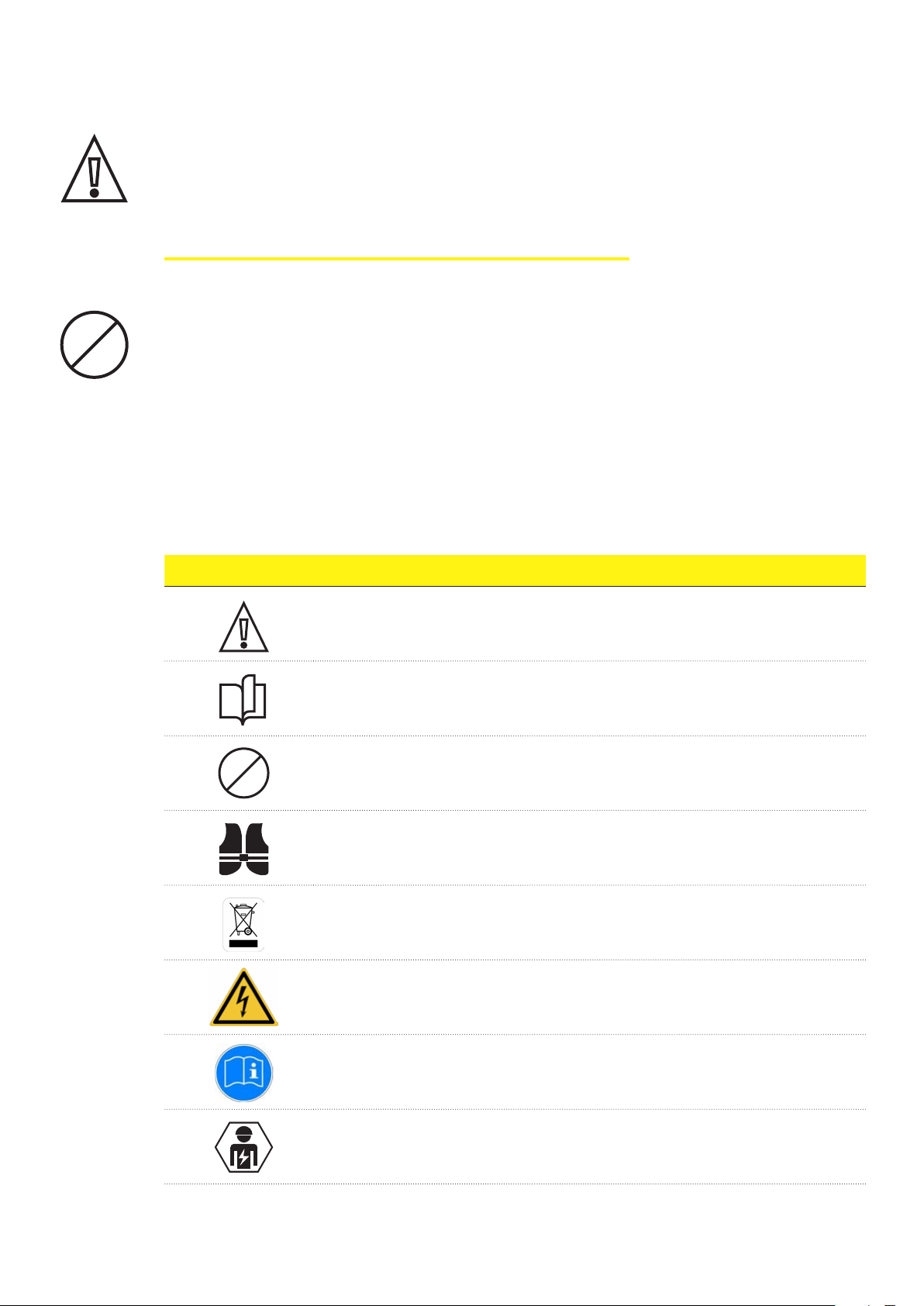
1.2 - Symbols and definitions
Symbol
GENERAL WARNING
THE ORIGINAL MANUAL OR OTHER ADDITIONAL DOCUMENTATION MUST BE CONSULTED
PROHIBITION OR RESTRICTIONS
THE OPERATIONS DESCRIBED MUST BE CARRIED OUT USING THE CLOTHING
AND/OR PROTECTIVE EQUIPMENT PROVIDED BY THE EMPLOYER
THE PRODUCTS SHOULD NOT BE DISPOSED OF WITH HOUSEHOLD WASTE,
BUT COLLECTED IN A DIFFERENT MANNER AS, ALTHOUGH NOT COMPOSED
OF MATERIALS HARMFUL TO HEALTH, THEY ARE MADE OF RECYCLABLE MATERIALS
HAZARD-WARNING SIGNAL: PRESENCE OF ELECTRICAL VOLTAGE
OBLIGATION SIGNAL: READ THE INSTRUCTIONS
THE INSTALLATION OF THE ELECTRONIC DEVICE SHOULD BE PERFORMED
ONLY BY QUALIFIED PERSONNEL
8
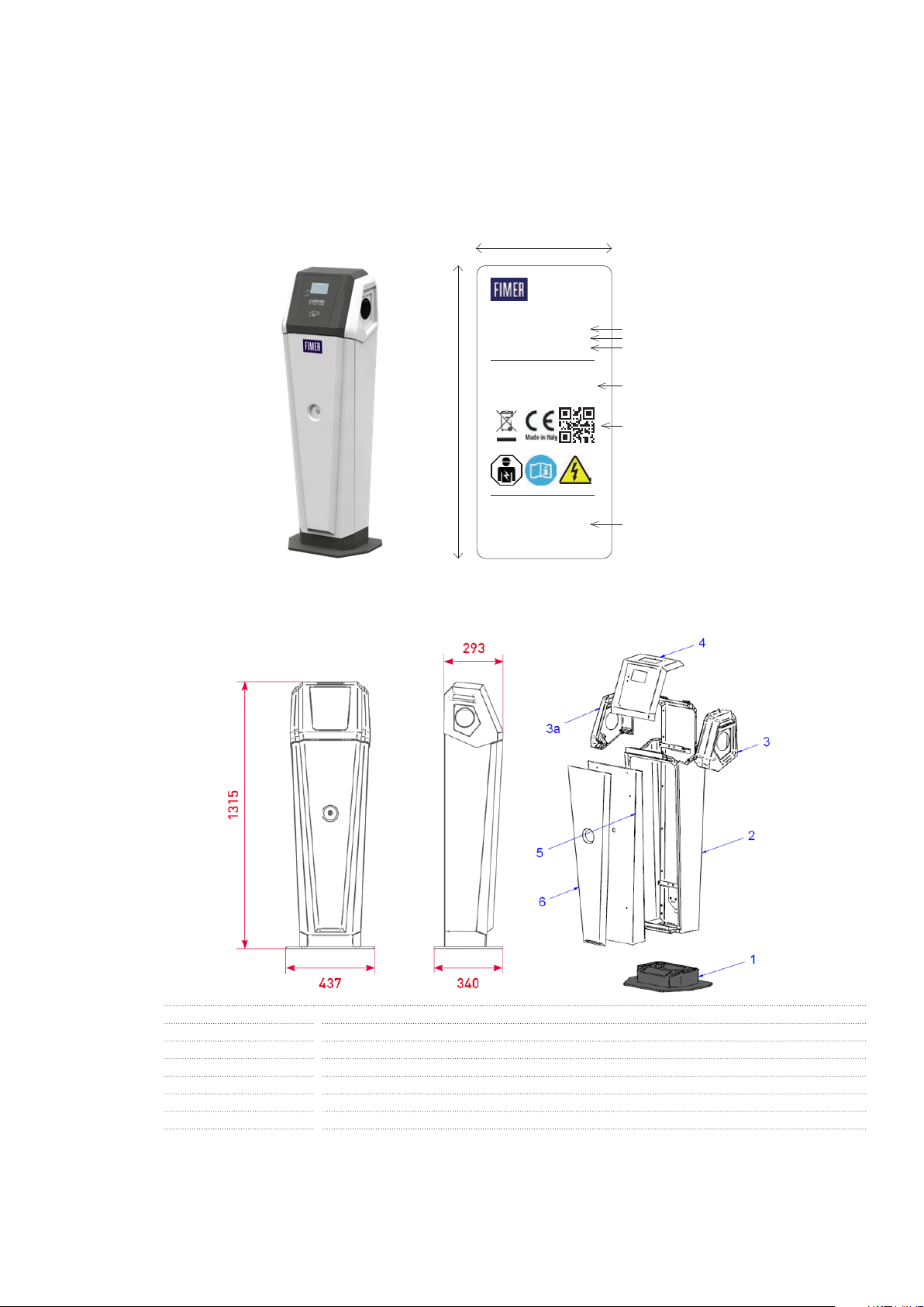
Regarding the symbols on the product nameplate, the indications not listed above are identified as follows:
1.3 - Product dimensions and charateristics
Weight: 48 kg
Dimensions: 1315 mm x 437 mm x 293 mm
1 Stand
2 Rear casing
3 Right side cover
3a Left side cover
4 Upper cover
5 Front door
6 Front shield
1.4 - Support
For any further information or request for support, FIMER is available through the dedicated section of the website www.
fimer.com or by writing to service.emobility@fimer.com
UN= 400 V AC ~
3P + N + PE
IP54IK08
Fimer Spa
Via Tortona, 25
I 20144
Milano (MI)
FIMER FLEXA AC STATION
FUTURE NET
Desc:
EAN:
FLSFN2222SM400
8033049748239
P/N:
S/N:
WO:
SO:
3Q752210400F
12345679890
xxxxxxxxxxxxx
xxxxxxxxxxxxx
Fimer Flexa AC Station FN 22kWx2 T2x2
ln=64 A ~
fr=50/60Hz
-25...+50°C
IEC 61851-1
Product description
Product Commercial Code
Europe Product Article Code Number
Electrical Characteristic of Product
QR Code Serial Number (S/N)
Part and Serial Number data
130 mm
45 mm

9
2 - Safety and equipment
2.1 - Safety warnings
Please read this document carefully before installing and starting up the product.
The installation and start-up phases of the device must be carried out exclusively by qualified personnel, able to identify
hazards and act safely.
The phases of maintenance, repair or subsequent repositioning must also be carried out only by qualified personnel:
there are no components that can be repaired by the user or maintained independently.
The product must not be operated by children or persons not considered able to assess the installation-related risks.
Pets and non-domestic animals must be kept away from the appliance.
Total or partial non-compliance with the indications contained in this document can lead to serious or fatal injuries.
The qualified installer must always ensure that the installation takes place in accordance with the local regulations in
force at the time of installation.
2.2 - Compliant use
The device requires grounding by a dedicated equipotential cable, to be connected in the grounding terminal inside the
device.
In any case, before installation, it is necessary to verify that the power supply system is fully compliant with the state of
the art and provided by qualified personnel in accordance with local and international regulations in force.
It is only safe to use the device if it is used as intended.
Different uses and unauthorized modifications to the appliance or any of its components are therefore impermissible
and are thus considered non-compliant.
The device is designed to be connected and to communicate information and data via a network interface. Users are
solely responsible for consistently providing and ensuring a secure connection between the product and their data
network or any other network (as applicable). Users should establish and maintain all appropriate measures (such as,
but not limited to, installing firewalls, applying authentication measures, encrypting data, installing anti-virus programs,
etc.) to protect the product, the network, their system and interface against any type of security breach, unauthorized
access, interference, intrusion, loss or theft of data or information. FIMER and its affiliates are not liable for damages or
losses related to such security breaches, any unauthorized access, interference, intrusion, leakage or theft of data or
information. The data, examples and diagrams in this manual are included only with the aim of describing the product
and should not be considered as a guaranteed declaration of ownership. All persons responsible for installing the
equipment indicated in this manual must ensure that each intended installation is suitable and acceptable, including
compliance with any applicable safety or other operational requirements. In particular, any risk in applications where a
system or product failure would create a risk of damage to property or persons (including but not limited to personal
injury or death) will be the sole responsibility of the person or entity installing the equipment; those responsible are
encouraged to ensure that all measures are taken to exclude or mitigate such risks.
This document has been carefully checked by FIMER but deviations cannot be completely ruled out. If errors are
detected, the reader is kindly requested to notify FIMER. Other than under explicit contractual commitments, in no event
shall FIMER be responsible or liable for any loss or damage resulting from the use of this manual or from the installation
of the equipment.
2

10
The product is not suitable for free display on the Internet. To ensure maximum security of information and operation,
the device must remain protected from any attempt to contact it via the Internet and therefore a communication can
only be originated from the device and not vice versa.
If you require further information, support or cybersecurity reports, you can write to itteb.cybersecurity@fimer.com.
2.3 - Product handling
The total weight of the product without packaging is approximately 48 kg: make sure to use a suitable tool for
handling.
Transport and store in a dry place away from heat sources (as specified in the technical specifications), only in the
original packaging.
Never grab the product from the charging connectors.

11
3 - Installation
CAUTION: Failure to observe the instructions provided in this manual can cause serious damage to both the product
and the installer (in the most serious cases, injuries can be fatal). Before proceeding with the installation, start-up and
use of the product, you should carefully read the instructions in this manual. FIMER recommends using experienced
professionals, who comply with current regulations, to install the product correctly.
The Wallbox device is intended for installation in Europe and Australia only.
The following table shows the main local limitations prescribed in IEC 61851-1 that the installer must consider before
proceeding with choosing and installing the device. However, it remains the responsibility of the installer to verify that
these standards are still in effect, and especially to verify the existence of any additional local standards that may limit
the use of such devices in the chosen country:
3.1 - Preparing for installation
Before installing, make sure that:
• Input power supply is completely switched off and remains off until installation is completed
• The work area is adequately marked and isolated (access to people not required for the work must be prevented)
• Installation should not be done with wet hands and no water jet may be directed at the product
• Do not install in conditions of rain, fog, or high humidity
• The packaging of the product is perfectly intact and without obvious damage (if the product is damaged, contact your
seller or request support at www.fimer.com)
• The product and all components (including cords) are perfectly intact and without any defects or obvious faults
To ensure the correct operation of the product, referring to local regulations in force, calculate the distance between the
power supply panel and the installation site properly to determine the voltage drop, cord thickness and existing load,
which are useful for identifying the maximum operating current.
The entire electrical power supply system to which the product is connected must first be correctly sized by a qualified
professional. The electrical data of the device, which must be consulted for the correct sizing of the power supply
system, are the data on the label of the device itself.
When installing this product, you must comply with all local and international standards for the construction and installa-
tion of electrical/electronic equipment, including but not limited to IEC 60364-1 and IEC 60364-5-52.
The power supply system must meet the following requirements:
• TN or TT system, in both cases with PE cord
• Three-phase power supply: 230/400 V AC ± 10% - 50Hz/60Hz
Paese National limitations
US Device not suitable for this country
CA Device not suitable for this country
JP Device not suitable for this country
DK
The reclosing function of the differential switches (ARD) must be disabled
the disabling of the reclosing function of the differential switches must be carried out by qualified FIMER personnel
UK
The reclosing function of the differential switches (ARD) must be disabled
the disabling of the reclosing function of the differential switches must be carried out by qualified FIMER personnel
FR
The reclosing function of the differential switches (ARD) must be disabled
the disabling of the reclosing function of the differential switches must be carried out by qualified FIMER personnel
CH
The reclosing function of the differential switches (ARD) must be disabled
the disabling of the reclosing function of the differential switches must be carried out by qualified FIMER personnel
3
12
3.2 - Tools required
1. Cutter
2. Flathead screwdriver or screwdriver
3. Torque wrench for hexagonal screws
4. Marker/pencil
5. Drill and 12mm diameter tip, suitable for the material of the fixing surface to be drilled
6. Hexagonal wrenches
7. Wire stripping pliers
FIMER declines all responsibility for damages to property or persons deriving from the use of these instruments. The
installation must be carried out by qualified personnel and in accordance with the regulations in force for the installation
of electrical equipment.
3.3 - Pakage contents
• 1 FIMER FLEXA AC Station
• 4 Anchor devices M12x105
• 1 MASTER RFiD card (only for the Local Controller version) and 2 USER RFiD cards
• 2 Keys for opening the front door
• Installation manual, guarantee certificate and declaration of conformity
3.4 - Space and positioning
Before choosing a location for this product, consult the electric vehicle's manual and follow any applicable guidelines.
Ensure that there are no heat sources, flammable substances, or electromagnetic sources in the installation area either
during the product installation phase or throughout its life.
In addition, the installation site must be sufficiently ventilated to ensure proper heat dissipation.
For mobile cellular or Wi-Fi versions of the product, make sure the selected area has cellular reception or Wi-Fi
coverage.
Before installation, make sure that the environmental conditions (such as temperature, altitude and humidity) according
to section 1.1 of the product specifications are met.
To ensure the functionality of the device and to guarantee its correct use by the user, the space around the device must
be free to allow air circulation, maneuvering the cords, recharging operations by the user and routine and extraordinary
maintenance in safety.
In addition, the space required to park the electric vehicle for recharging must be taken into consideration.
For locations where the device will be exposed to direct sunlight or weather for most of the day, it is recommended to
install a cover to protect the charging station.
Also:
• Make sure the charging device is protected from collisions by barriers or poles;
• Design the parking layout for easy access to the charging cord;
• Provide a comfortable environment for users, providing safety against vandalism or theft;
• Install the charging device in a location where it can be clearly seen or monitored;
• Install sufficient lighting around the device.
3.5 - Unpacking
Before proceeding with the installation of the device, it is necessary to check, upon unpacking, that the various parts of
the device do not present physical damage due to shocks, tears or abrasions.
If any damage is detected, stop the installation procedure immediately and contact technical support as described in
section 1.4.
The various components are protected by packaging and adhesive tapes. Before installation, each component must be
cleared of any traces of dust, the packaging or adhesive tapes.
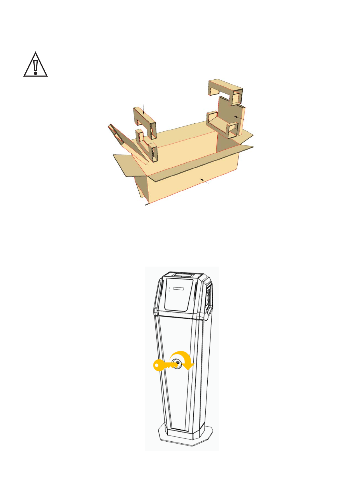
13
The following images are for illustrative purposes only; they may not show all internal components of the product or
present negligible differences from the actual configuration
1. Open the main packaging
2. Using appropriate handling equipment, remove the station from the enclosure and place it horizontally on the work
surface
3. Using the supplied key, open the front lock

14
4. Slightly open the lower part of the door and, using the flathead screwdriver, unhook the grounding wire from the
clamp to which it is hooked
5. Since the front door is no longer fastened to the station, it can be removed completely

15
6. Remove the main disconnect switch’s terminal covers and remove the two drain hoses from the 2 metal hose
adaptors
7. Using a ratchet for hexagonal screws, unscrew the 4 fixing bolts and their washers from the bottom of the station,
separating the stand and the plate from the station with cord glands (CAUTION: as indicated in step 2, be sure to
place the station on a horizontal plane before removing the hexagonal screws to avoid dropping the station body
when removing the screws)
3.6 - Anchor device installation
The following images are for illustrative purposes only; they may not show all internal components of the product or
present negligible differences from the actual configuration.
3.6.1 Installation on existing ground
1. Place the stand on the ground where you want to install the product (in any case respecting the indications
previously provided on the subject of positioning) and letting the corrugated pipe come out of the ground for about
3-5cm

16
2. Using the stand as a template, make marks on the floor at the position of the 4 present holes
3. Remove the stand and drill holes in the ground at the position of the 4 marks previously made with a 12mm drill bit
to position the anchoring devices. The maximum drilling depth is 60mm for at least 120mm thick soils, and 80mm for
at least 160mm thick soils. Then, clean the hole made from any debris of drilling
4. If the installer wants to further increase the seal, it is possible to inject in the 4 holes just made some resin anchor
(or chemical)
5. Remove pre-screwed bolts and washers from the anchor devices
6. Insert the 4 anchor devices into the 4 holes just drilled
7. Place again the stand at the position of the anchor devices (so that the threaded parts protruding from the ground
pass through the holes in the stand), pass the corrugated cord through the stand and secure it to the ground using
the 4 bolts and 4 washers previously unscrewed from the anchor devices (use a tightening torque of 62-79Nm)

17
3.6.2 Installation in fresh concrete
In case of installation in concrete plinth, it is necessary to use the plate with clamps (not included in the standard
package) following the following procedure:
1. Install the plate with clamps inside the concrete casting, making sure that only the clamps are submerged, while the
horizontal plate should barely emerge from the surface
2. Once the concrete solidified, place the stand on top of the upper part of the plate with clamps, so that the protruding
threaded parts pass through the holes in the stand, and run the corrugated cord through the stand
3. Fasten the stand to the plate with clamps using M10 bolts and M10 washers (available in the clamp base package)
to be screwed onto the protruding threaded parts with a tightening torque of 36-46Nm

18
2. Reuse the Ø10 hex head screws and Ø10 washers (previously removed during unpacking) to secure the plate
with cords gland to the bottom of the station (and consequently the station to its stand) with a tightening torque of
36-46Nm
3. Reattach the two drain hoses to the 2 metal hose adaptors
3.7 - Charging station installation
During installation, prevent the electrical connection of the power supply; the entire work area must be cordoned off and
only qualified and authorized personnel may access it.
The power supply to the equipment must remain off. Failure to follow these instructions could result in serious injury or
death.
Make sure to keep the station in a vertical position by using appropriate safety equipment during the entire phase of
fixing the station to the stand
The following images are for illustrative purposes only; they may not show all internal components of the product or
present negligible differences from the actual configuration
1. Using special handling equipment, place the station on top of the stand previously secured to the ground and run the
cords through the bottom of it. Bring the plate with the cord glands to the area where the cords come out, loosen the
main cord gland and pass the multipolar cord through it. Finally, lay the plate with the cord glands on the bottom of
the station:
19
3.8 - Power and grounding cord connection
During installation, prevent the electrical connection of the power supply; the entire work area must be cordoned off and
only qualified and authorized personnel may access it.
The equipment should be powered through properly sized cords with appropriate resistance for the current flow for
which the product was designed. Before wiring, ensure that the cords are properly sized and that the maximum
allowable bending radii are not exceeded. The electrical data of the device, which must be consulted for the correct
sizing of the power supply system, are the data on the label of the device itself.
The power supply to the equipment must remain off throughout this step.
Failure to follow these instructions could result in serious injury or death.
The images below are for illustrative purposes only and may not show all internal components in the product.
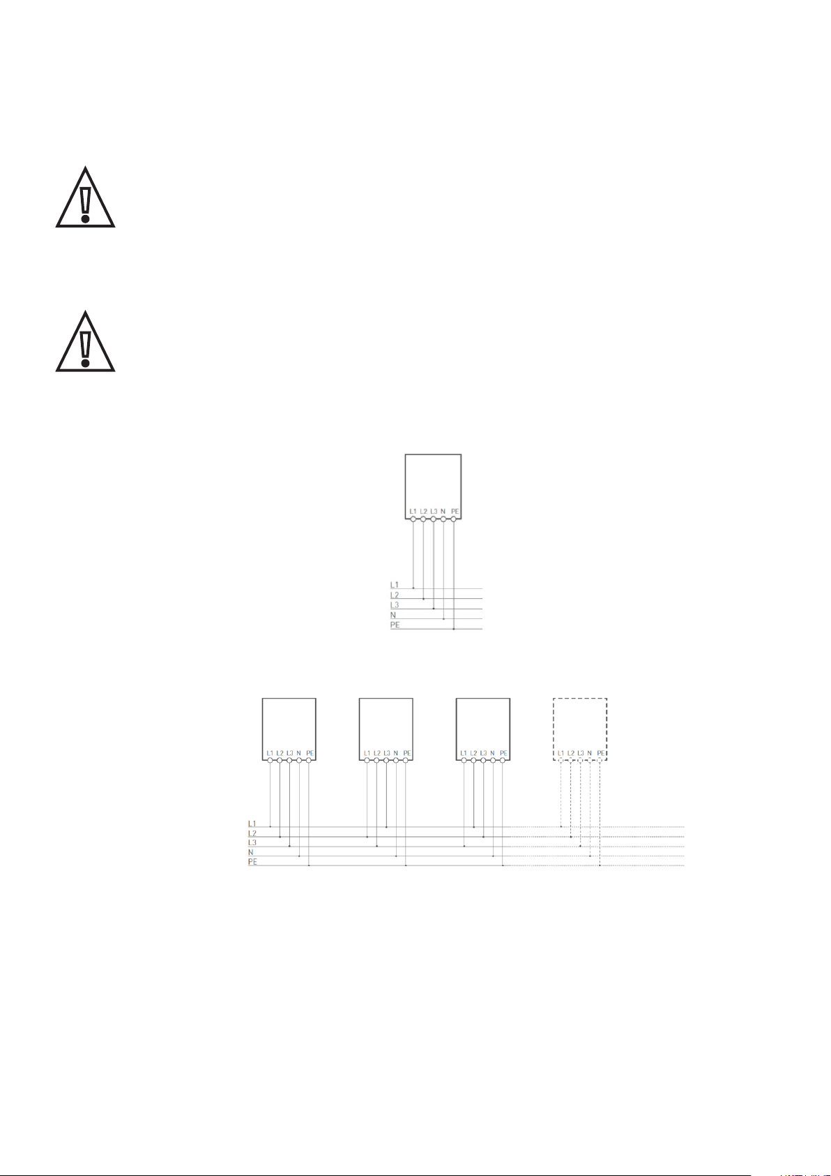
The following diagram shows how to electrically connect the station:
In the case of multiple installations, it is suggested a phase rotation as follows:
In the station are already contained differential protection devices (complying with one of the following standards: IEC
61008-1, IEC 61009-1, IEC 60947-2 and IEC 62423) and magnetothermal (complying with IEC 60947-2, IEC 60947-6-2
or IEC 61009-1 or with the relevant parts of IEC 60898 or IEC 60269). Other types of protection (e.g., overvoltage
protection) are not included.
In particular, T3A sockets are protected by two-pole magnetothermal protection (D curve, 20 A, 10 kA) and two-pole
pure differential switch (type A, 25 A, 30 mA) with the addition of a DC 6mA direct current monitoring device, while T2
sockets are protected by four-pole magnetothermal switch (D curve, 40 A, 10 kA) and four-pole pure differential switch
(type A, 40 A, 30 mA) with the addition of a DC 6mA direct current monitoring device
.

20
The following guidelines provide information regarding the power cords to be used and the recommended conductor size:
Multipolar cord outer diameter: 28÷38 mm
Recommended conductor cross-section: 25÷35 mm²
Wire stripping length:
• Main disconnect switch terminal block (L1-L2-L3-N): 18÷21 mm
• Grounding clamp: 17 mm
The following table shows the maximum length of the conductors in relation to the chosen section:
For mode 3 case B the cords used for charging the vehicle must have a minimum I²t value of 75 000 A²s
1. Pull the multipolar cord, leaving some space inside the column, and tighten the cord gland (making sure the remaining
cord glands are also tightened)
AC Station version
[type of sockets] In (A) Cross-section of conductor
[mm2]
Maximum conductor length
[m]
T2-T3A 48 25 152
T2-T3A 48 35 210
T2-T2 64 25 114
T2-T2 64 35 158
This manual suits for next models
3
Table of contents
Other Fimer Batteries Charger manuals


