Fimer MVCS User manual

Medium Voltage
Compact Skid
FIMER solar
Hardware manual


Medium Voltage Compact Skid
Hardware manual
1
2
3
4
5
6
7
8
9
10
11
Table of contents
Safety instructions
Introduction to this manual
Hardware description
Storing, lifting and transporting
Mechanical installation
Electrical installation
Finalizing the installation
Start-up and operation
Maintenance
Technical data
Documents

Contents
06
06
06
07
07
07
07
08
09
10
10
10
11
11
11
11
12
12
13
15
16
17
18
19
19
20
20
21
22
22
23
23
24
25
26
26
Safety instructions
• Allowed usage
• Safe installation, start-up and maintenance
• General safety instructions
• MVCS working area safety
–Personal Protective Equipment (PPE)
–Safety instructions for MV switchgear and MV transformer area
–Safety instructions for the auxiliary services board
• Safe operation
Introduction to this manual
• Related documents
• Terms and Abbreviations
Hardware description
• Product overview
–Mechanical characteristics
• Layout drawing
–Working areas and main components
• Main Components Overview
–MV Switchgear
–MV Transformer
–AC Cabinet
–Inverter inputs (A)
–Auxiliary service board (B)
• List of signals
• Main circuit diagram
• Type designation label
• MVCS Configuration
–MVCS optional codes
Storing, lifting and transporting
• Storing
• Lifting
–Lifting instructions
• Transporting
• Unloading
–Unloading Instructions (truck shipping)
–Unloading Instructions (container shipping)

Mechanical installation
• Foundation guidelines
–Placing the MVCS on the foundation
–Fastening the MVCS
• Constructing earthing electrode and earthing
• Filling the pit and finalizing the surroundings
Electrical installation
• Routing the cables
• LV busbar interconnection
• Earthing
–Protective earthing (grounding) inside the MVCS
–Measuring the insulation resistance of the cabling
• Connecting the inverter inputs
• Auxiliary and Communication Interconnection
• MV Side (Grid) Interconnection
Finalizing the installation
• Finalizing the installation
• Checking the installation of MVCS
–Commissioning Pre-Conditions
–Pre-Commissioning Checklist
Start-up and operation
• Start-up procedure
Maintenance
• Maintenance intervals
–Annual maintenance
–Maintenance intervals
• Cleaning procedure
• Maintenance of painted surfaces
–Repainting the scratched areas
–Painting the damaged surface (no visible rust)
–Painting the damaged surface (visible rust)
–Maintenance of Zinc coated surfaces
• Maintenance of grounding bars and points
Technical data
• Technical data and types: MVCS
Documents
• List of documents
27
27
27
28
29
29
30
31
31
32
32
32
32
33
33
34
34
34
34
35
38
38
40
42
42
42
42
44
44
44
44
44
45
46
46
48
48
6
1
Safety instruction
1 - Introduction to this manual
Contents of this chapter
This chapter presents the use of warnings in the manual and gives instructions for safe installation, start-up, use and
maintenance of the Medium Voltage Compact Skid “MVCS”.
Use of warnings
Warnings caution you about conditions which can result in serious injury or death and/or damage to the equipment
and advise on how to avoid the danger. The following warning symbols are used in this manual:
WARNING!
Electricity warning warns of hazards from electricity which can cause physical injury and/or damage to the
equipment.
WARNING!
General warning warns about conditions, other than those caused by electricity, which can result in physical injury
and/or damage to the equipment.
WARNING!
General warning warns about weather conditions, prohibited maintenance operations during a typhoon, thunder-
storm, snow, rain, and electrical storm. Maintenance in such conditions can result in physical injury and/or damage
to the equipment.
WARNING!
General warning warns about maintenance work on the roof which should always be done from the outer perimeter,
considering the local safety regulations.
Allowed usage
• The Medium Voltage Compact Skid “MVCS”, is designed to group the energy generated by a group of string
inverters and adapt it to the power grid. Use the MVCS only at its permissible input/output ratings and ambient
conditions. Make sure this compliance is satisfied before commissioning.
• The operation and maintenance of the MVCS must be carried out by certified technicians that fulfill all local skill
set and safety requirements. Any unqualified personnel must maintain a safe distance from the MVCS. All activi-
ties must be in accordance with the criteria described in the FIMER technical documents and local regulations.
• Make modifications to the MVCS only with authorization of FIMER. Any alterations done outside FIMER approval
will invalid the warranty for the product. FIMER is not liable for any damages caused by these changes.
• The MVCS is a non-walk-in type station, designed to be operated from the outside. Make sure the side doors are
closed at all times during operation and that no personnel is inside or in the near vicinity of the MVCS.
Safe installation, start-up and maintenance
This section contains the safety instructions which you must follow when installing, commissioning, and maintaining
the MVCS. If ignored, physical injury or death may follow, or damage may occur to the equipment.
• Only authorized electricians/personnel are allowed to install, start-up and doing maintenance on the MVCS.
Working methods, tools, components etc. must follow the IEC regulations.
• Obey all local safety regulations concerning electrical sub-stations.
• The MVCS should be energized and de-energized only by an authorized person who has the task-specific instruc-
tions for the operation of an MV substation and permission from the on-site foreperson in charge of electrical
work.
• If other people must be in the vicinity while the door is open, warn them, and if required, provide supervision and
guidance.
7
General safety instructions
WARNING!
Before you perform any work in the MVCS, obey the following safety precautions.
1. Obtain a work permit.
2. Clearly identify the work location.
3. Read the safety instructions of the working area and the component you are working on.
4. Make sure that there is no voltage presence in the working area you are going to work on, see Safety instructions
for MV switchgear and MV transformer area and Safety instructions for the auxiliary services board.
5. Secure against reconnection.
6. Use a voltage tester to ensure that there is no voltage in working area.
7. Make sure that the MVCS is properly grounded.
8. Secure against reconnection.
9. Use protection against any live parts.
10. Take special precautions when you work close to exposed conductors.
MVCS working area safety
The MVCS has three main working areas:
• AC Cabinet Area
• MV Transformer Area
• MV Switchgear Area
Each working area has separate safety instructions.
Personal Protective Equipment (PPE)
• Perform any operation on the equipment with suitable work clothes and instruments.
• When choosing a personnel protective equipment, consider environmental conditions such as humidity, noise, etc.
and local regulations.
• The minimum required safety equipment is as follows:
–Safety shoes
–Safety gloves
–Safety glasses
–Head protection
–Hearing protection
–Work clothes
Safety instructions for MV switchgear and MV transformer area
WARNING!
Perform the below instructions before you start working inside the MV switchgear and/or MV transformer area. Ignoring
the instructions can cause physical injury or death, or damage to the equipment.
1. Obtain a work permit.
2. Identify the MV switchgear and read its safety instructions.
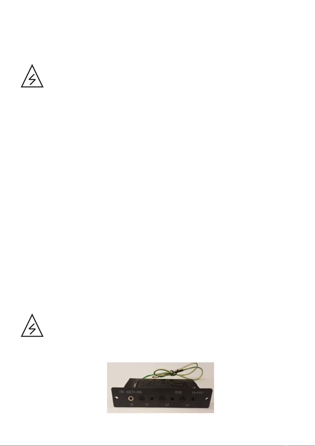
3. Check the operation of the capacitive voltage indicators in all MV switchgear bays (all phase LEDs are switched on
when a voltage is connected). Capacitive voltage indicators:
1 - Introduction to this manual

8
4. Disconnect the MV switchgear from the grid and all possible power supplies (external, auxiliary, and inverters as well as any parallel
connection stations), secure by locking and tagging.
a. Stop the string inverters outside the MVCS. Open the DC disconnecting switches in each inverter unit and add warning notices. If appli-
cable, open the AC disconnecting switches in each inverter unit, lock and add warning notices.
b. Open all auxiliary breakers, switches and fuses in the auxiliary service board, lock and add warning notices.
c. Open main low voltage circuit breaker (if present), and all fuse base switches of the inverter inputs (AC Cabinet), lock and add warning
notices.
d. Turn the vacuum circuit breaker of the MV switchgear (V/L module) to open position. Lock and add warning notice.
e. Turn the disconnecting switch of the MV switchgear (V/P module) to open position. Lock and add warning notice.
f. Turn the earthing switch of the MV switchgear (V/P module) to earthed position. Lock and add a warning notice.
g. Turn the disconnecting switch of the MV switchgear (C/L modules) to open position. Lock and add a warning notice.
h. Turn the earthing switch of the MV switchgear (C/L modules) to earthed position. Lock and add a warning notice.
i. With above operation the MV Switchgear, and so the MVCS, should be disconnected. See “Switchgear”, “MVCS Interconnection Cables
and Electrical Layout” and the general scheme of the PV plant to assure that no external supply is connected to the MV Switchgear.
5. Check that all shrouds/screens are in place.
6. Check that you are not near to any live parts while working. All live circuits must be protected with shrouds/screens.
7. Make sure that the MV switchgear is dead.
–Check the status of voltage indicators in all MV switchgear bays. Also note that all phase LEDs which were switched on AC cabinet
before step 3 are now switched off).
8. Check that the MV transformer is dead (high voltage terminals, low voltage terminals, any auxiliary power, and instrumentation). Use an
appropriate high voltage tester only for the high voltage side, and a voltage detector with suitable testing heads for the low voltage side.
Safety instructions for the auxiliary services board
1. If there is no main low voltage circuit breaker installed in the power section, then follow Safety instructions for MV switchgear and MV
transformer area
a. Check that there is no voltage presence, with a voltage tester, neither in the power section nor in the auxiliary services board.
2. If main low voltage circuit breaker is installed, then follow:
a. Obtain a work permit.
b. Open the main circuit breaker or main switch upstream auxiliary service transformer, secure by locking and tagging.
c. Open the circuit breaker downstream auxiliary service transformer, secure by locking and tagging.
d. Open all switches, breakers, and connectors of the auxiliary service board, and secure by locking and tagging.
e. Make sure you are not near to any live parts while working. Disconnect the live circuits or protect them with shrouds/creens.
f. Check the status of the voltage indicators in the auxiliary service board.
g. Check that the auxiliary service board is dead.
1 - Introduction to this manual

9
Safe operation
This section contains the safety instructions which you must follow when operating the MVCS. If ignored, physical
injury or death, or damage may occur.
WARNING!
Obey these instructions to prevent injury, death, or damage to the equipment.
WARNING!
Keep all doors locked while the MVCS is operating. Allow access to only authorized personnel.
1. Keep all doors of the MVCS closed during operation. Give the keys only to authorized personnel.
2. Before you start a group of inverters, check the connections of each inverter input, and the recommendations in
the specific inverter manual.
3. Do not open the AC base fuse switches when the MVCS is operating.
4. Before you adjust the group of inverters and set them into service, make sure that all of them are suitable for
operation.
5. Do not use the inverters in a manner not specified in the manual.
Notes:
Spend as little time as possible near the inverters or the MVCS.
1 - Introduction to this manual

Contents of this chapter
This chapter provides information about the manual such as applicability, target audience and contents. It also lists the related documents.
Applicability
This manual is applicable to Medium Voltage Compact Skid “MVCS”.
Target audience
This manual is intended for personnel who transport, store, plan the installation, install, commission, and maintain the MVCS.
Read this manual before working on the MVCS. You are expected to know the fundamentals of electricity, wiring, electrical components,
and electrical schematic symbols.
Related documents
Terms and abbreviations
IEEE device no. references
2
Introduction to this manual
2 - Introduction to this manual
Inverter manuals and guides
PVS-175-TL Product Manual FIMER_PVS-175-TL A.1 Version_Product manual_EN_RevC.pdf
PVS-175-TL Quick installation guide PVS-175-TL-Quick Installation Guide EN-REVA CC.pdf
PVS-175- TL data sheet FIMER_PVS-175-TL_EN_RevB.pdf
PVS-100/120-TL Product Manual FIMER-PVS-100_120-TL-B version-Product manual EN-Rev A
PVS-100/120-TL Quick installation guide PVS-100_120-TL - Quick Installation Guide EN - RevB
PVS-100/120-TL data sheet FIMER_PVS-100-120-TL-6MPPT-2MPPT_EN_RevA
Term/ Abbreviation Description
AC Alternating current
CV/CCV Construction of MV switchgear (L+P/ 2L+P)
DC Direct current
HC High cube container
LV Low voltage (50...1000 V AC)
MV Medium voltage
MVCS Medium voltage compact skid
LVMCB Low Voltage Main Circuit Breaker
PPE Personal protective equipment
SF6 Sulfur hexafluoride (this gas type is used in MV switchgear).
SWG Switchgear
THD Total harmonic distortion
IEEE Protection function
27 Undervoltage
50 Instantaneous Overcurrent
50N Neutral Instantaneous Overcurrent
51 AC time overcurrent
51N Neutral Time Overcurrent
59 Overvoltage
68 Transformer inrush detector
81 Medium voltage
List of documents
See List of documents.
Note: The drawings are delivered with the unit only on request -
11
Contents of this chapter
This chapter provides an overview of the Medium Voltage Compact Skid “MVCS”. It also includes layout, general data sheet of the main
components, type designation label and ordering information.
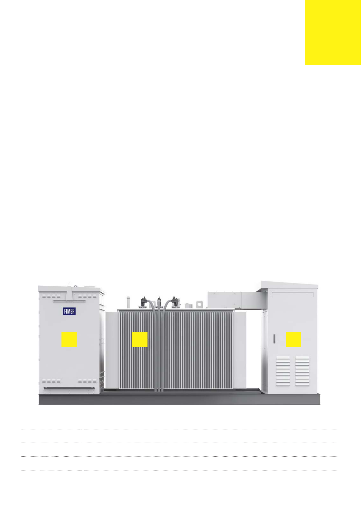
Product overview
The medium voltage compact skid connects a group of inverters to a medium voltage power grid. This solution is constructed around a
skid house that contains:
• MV switchgear—connects to the power grid. It is also the main protecting, switching, breaking and disconnecting equipment of the
medium-voltage side of the solar power plant.
• MV transformer—transforms low voltage from inverters to medium voltage for the power grid.
• AC cabinet—contains all parallel connections to the inverter inputs and the auxiliary service boards (required for the autonomous func-
tion of the MVCS). Note that the AC cabinet also includes an additional space for customer use (e.g. communication board, etc).
.
Mechanical characteristics
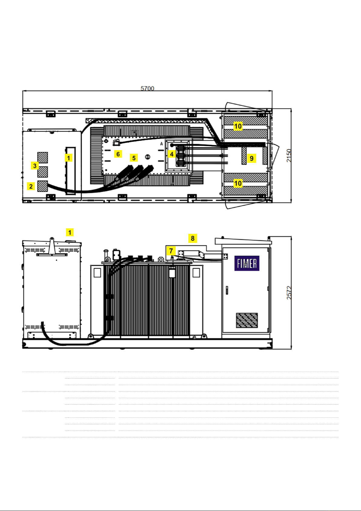
The MVCS is constructed over a skid, with the appropriate dimensions to be suitable to transport inside 20 ft or 40 ft HC container.
• External dimension (length, width, height) = 5700 x 2150 x 2580 mm.
• Total weight = 9-18 ton (may vary depending on MVCS final configuration).
Layout drawing
This section describes the working areas and main components of the MVCS. For additional information, request to your local FIMER sales
contact:
• “MVCS Structural Layout”.
• “MVCS Footprint”.
3
Hardware description
3 - Hardware desription
A MV switchgear area. For more information, see section MV Switchgear
B MV transformer area. For more information, see section MV Transformer
C AC cabinet area. For more information, see section AC Cabinet
A B C
12
Working areas and main components
Main Components Overview
A
1SF6 Outlet
2MV Input from transformer (V module)
3 MV Output (C module)
B
4 LV Connection Box
5 MV Bushings
6 Transformer Protection Device
C
7 Neutral Bushing
8 Busduct/Busbars
9 Auxiliary Section input
10 String Inverter cables access
3 - Hardware desription

13
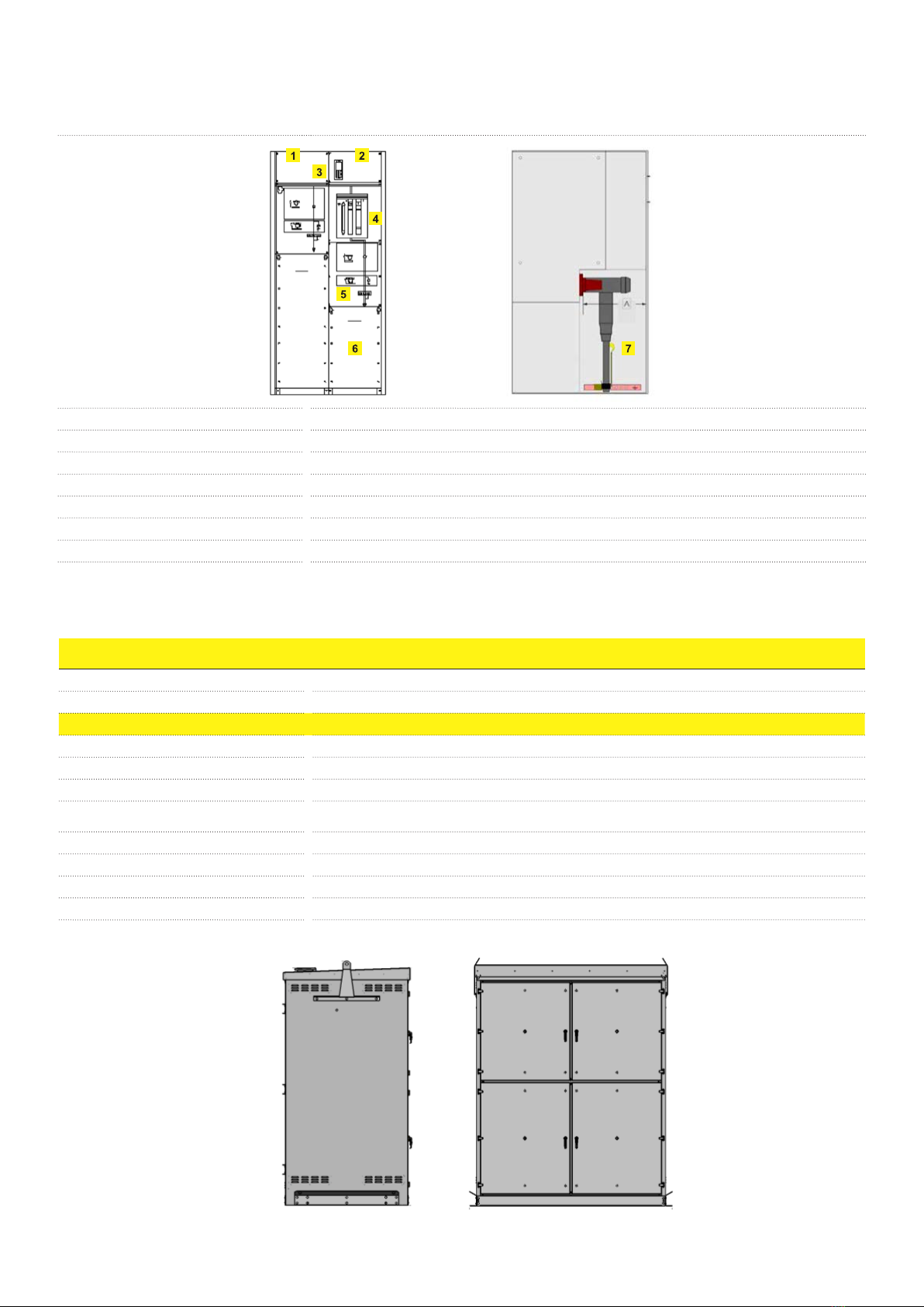
MV Switchgear
Medium voltage switchgears protect MV transformers and the MVCS in general, its also allow the MVCS to be connected to the Grid and
to other MVCS in parallel.
Technical Datasheet Environmental
Minimum Ambient Temperature -25 °C
Maximum Ambient Temperature
(No derating) 60ºC (40 ºC)
Max Altitude <1500 m asl
Relative humidity max. 24 hour mean 95%
Classification (IEC62271-200) LSC2A IAC AFL 16/20/25 kA x 1s → Indoor solution
LSC2A IAC AFLR 16/20/25 kA x 1s → Outdoor solution
SF6 Ventilation Backwards (exhaust channel) → Indoor solution
Downwards (cable trench) → Outdoor solution
Degree of Protection (IEC60529): IP3X (cable compartment) – IP2X (front cover)
IP54 for MV enslosure
Corrosivity protection Standard: C4
Upgrade: C5M
Rated Voltages 24 / 50 / 125 kV
36 / 70 / 170 kV
Frequency 50/60 Hz
Operating Voltage Up to 36 kV
Rated Current 630 A (@40ºC) 500 A (@60ºC)
Rated Short Circuit Current 20 kA – 1s
Internal Arc Fault withstand Standard (24kV/36kV): 16 kA - 1s/ 20kA – 1s
Upgrade (24kV/36kV): 20 kA - 1s/ 25kA – 1s
Configuration Standard: 1 Line Switches + 1 Trafo Feeders
Upgrade: 2 Line Switches + 1 Trafo Feeders
Electrical and mechanical class M1
MV Unit Composition
Line Switch 630A (C module), equipped as follow:
- Nr. 3 capacitive voltage indicators
- Manual line switch with earth position for the incoming
MV cables
- Key lock with key free for earth switch closed
- Simple incoming MV cable (one cable per phase)
Trafo Feeder 630A (V module), equipped as follow:
- Nr. 3 voltage indicators
- Manual line switch with earth position for the MV cables
- Key lock with key free for earth switch closed
- Circuit Breaker (motorized as optional)
- Standard: Nr. 1 electronic protection relay
(50/51-50N/51N)
Optional:Relay with additional protections (59-27-81..) and
measurement + comm functions as optional
- Nr. 3 CT
3 - Hardware desription
14
1 C module (L)
2 V module (P)
3 Protection Relay
4 Circuit Breaker
5 Interlocking
6 Cable compartment protection panel
7 Cable compartment
MV Outdoor Enclosure
This enclosure is included when indoor switchgear is installed.
Technical Datasheet
Minimum Ambient Temperature -25 °C
Maximum Ambient Temperature 60 °C
Classification AFLR
Degree of Protection (IEC60529): IP54
Degree of Protection (IEC62262) IK9/10
Corrosion class Standard: C4
Upgrade: C5M
Paint colour RAL7035
Cooling Natural
SF6 Ventilation Upper exhaust
Dimensions (WxLxH) 1676 x 1300 x 2238 mm
3 - Hardware desription

15
1 LV Bushings + Neutral terminal
2Off-Load Tap changer
3 MV Connectors
4 Earthing terminal and Oil Drain Valve
5 RIS2/DGPT2 (protection device)
6 Oil filling plug
MV Transformer
Technical Datasheet
Minimum Ambient Temperature -25 °C
Maximum Ambient Temperature (No derating) 60ºC
Max Altitude <1000 m asl
Reference Standard IEC60076-1
Cooling type ONAN
Power @30ºC Up to 6,66 MVA
Primary voltage Up to 36 kV
Secondary Voltage 0,8/0,48/0,4 kV
Voltage regulation range +/- 2x2,5%
Vectorial group Dyn11
Primary insulation class 24 / 50 / 125 kV
36 / 70 / 170 kV
Secondary insulation class (ph) 3,6/10/40
Secondary insulation class (N) 1,1/10/20
Losses Standard: EU 548/2014
Optional: EU 2019/17831
Short Circuit Impedance 5…8%
Frequency 50/60 Hz
Max Dimensions (LxWxH) 2650x1700x2200
Corrosion class Standard: C4
Upgrade: C5M
Painting RAL 7035
Load Power derating According nº of inverters and environmental conditions
Safety protection device RIS2/DGPT2 or similar
*This layout may vary depending on final MVCS configuration
1) Included as standard if destination country is in EU
3 - Hardware desription
16
Technical Datasheet
Minimum Ambient Temperature -25 °C
Maximum Ambient Temperature 50 °C
Max Altitude <2000 masl
Reference standard 61439-1 & 2
Max Dimensions (WxLxH) 2080x1200x2295 mm
Max Weight < 3000 kg
Ventilation Forced + Natural (> 3000 m3/h)
IP 54 (20 with doors open)
Corrosion class Standard: C4
Upgrade: C5M
Paint colour RAL 7035
Doors → Cubicles (nº)
-Front → Aux services + MCB (2)
-Lat. Left → Power Section 1 (1)
-Lat. Right → Power Section 2 (1)
Nº of Inputs (Power) Up to 36 (Up to 6,7 MVA)
Input protection Fuse gS NH1
Rated Voltage 800/480/400 V
Frequency 50/60 Hz
Conductor Copper Busbars
Surge Arrester Protection Type I+II
Aux Trafo Power Standard: 10 kVA
Upgrade: 20/30 kVA
Secondary Voltage 400-230 V
Spare Lines 2x16/10 A (1 ph)
Communication
MVCS signal concentration:
-2x Remote I/O module, Digital signals, Input, 8-channel, 2-conductor connection
-1x Remote I/O fieldbus coupler, Modbus/TCP
-1x Network switch, unmanaged, Fast Ethernet, Number of ports
Main Circuit Breaker Optional
UPS Optional
Energy Measurement Optional
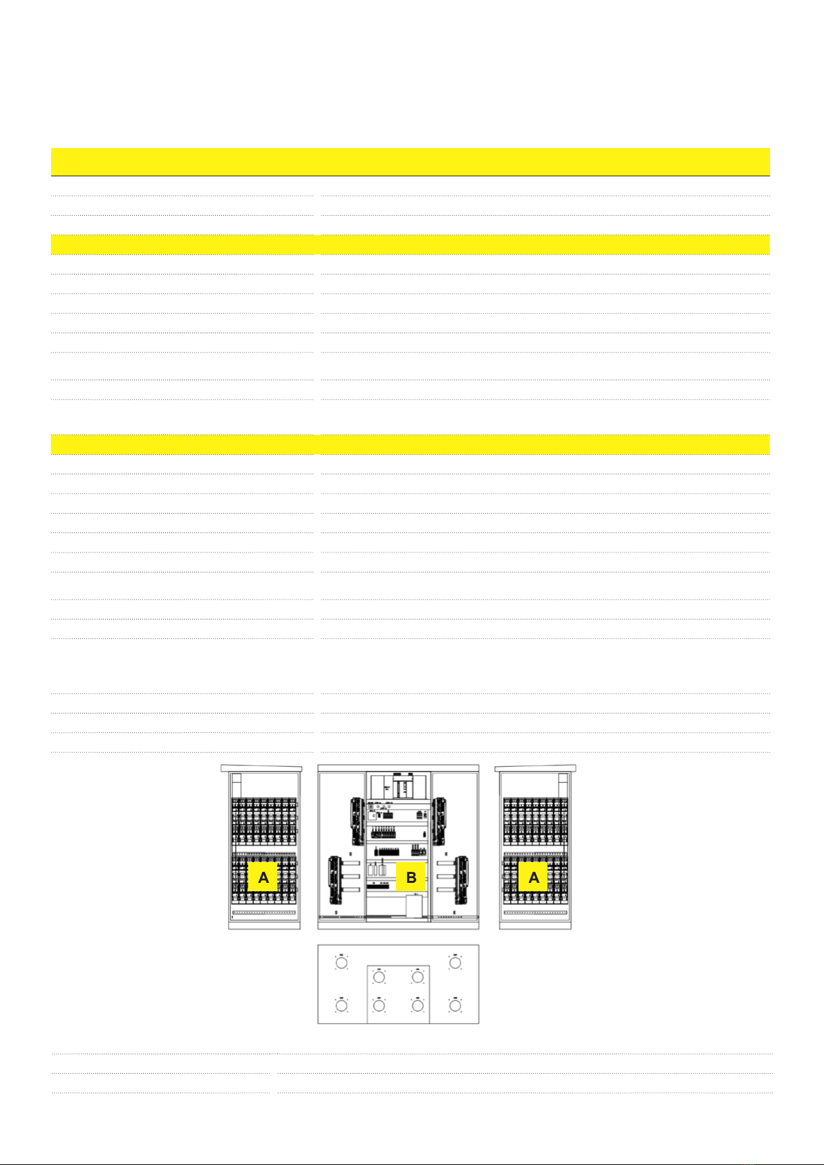
AC Cabinet
AInverter inputs. For more information, see section Inverter inputs (A)
BAuxiliary service board. For more information, see section Auxiliary service board (B)
*This layout may vary depending on final MVCS configuration
3 - Hardware desription
17
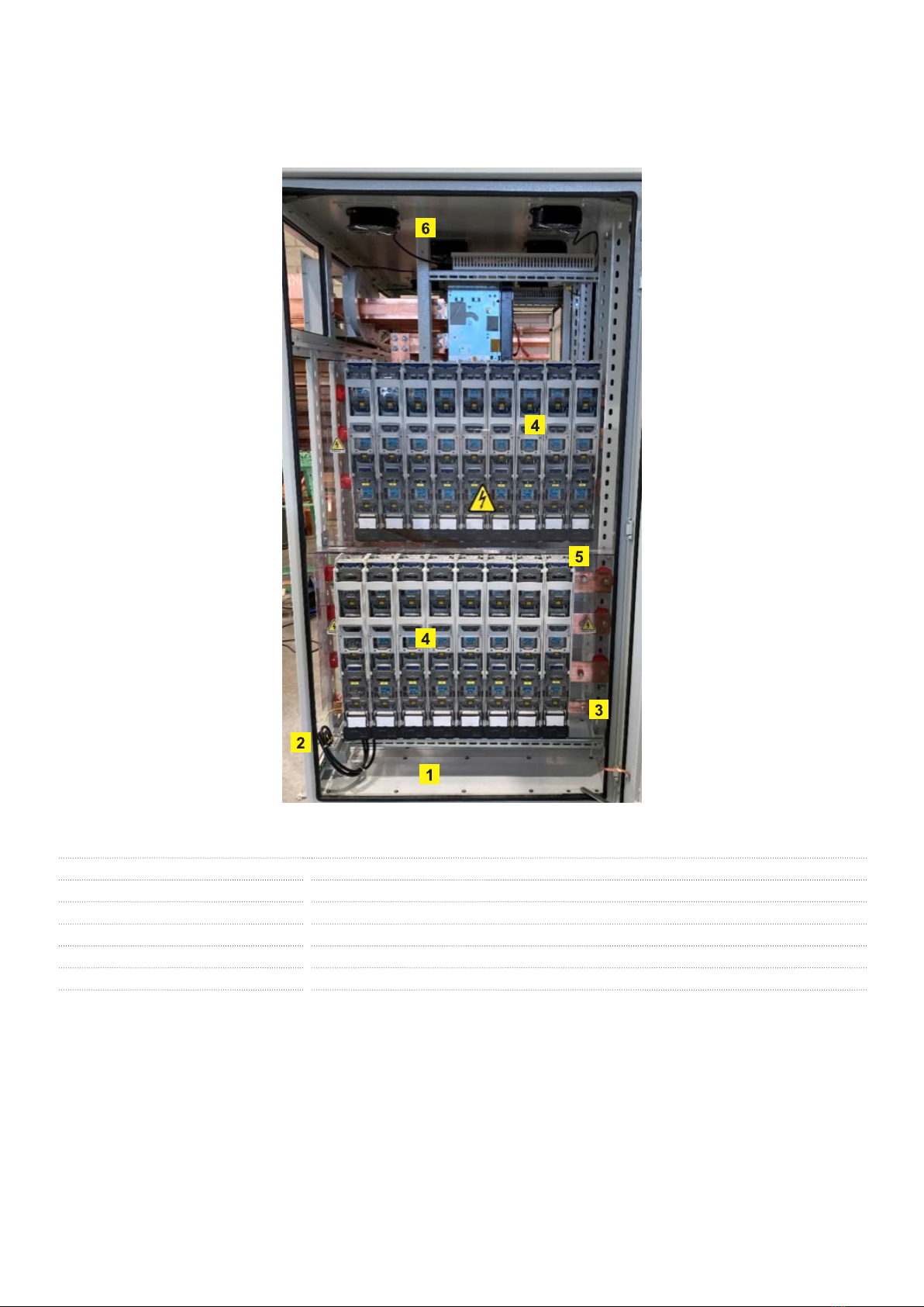
1Cover for incoming cables
2Surge arrester protection
3Grounding Busbar
4Fuse holders + fuses for inputs protection
5PVC protection cover
6Ventilation system
*This layout may vary depending on final MVCS configuration
Inverter inputs (A)
3 - Hardware desription
18
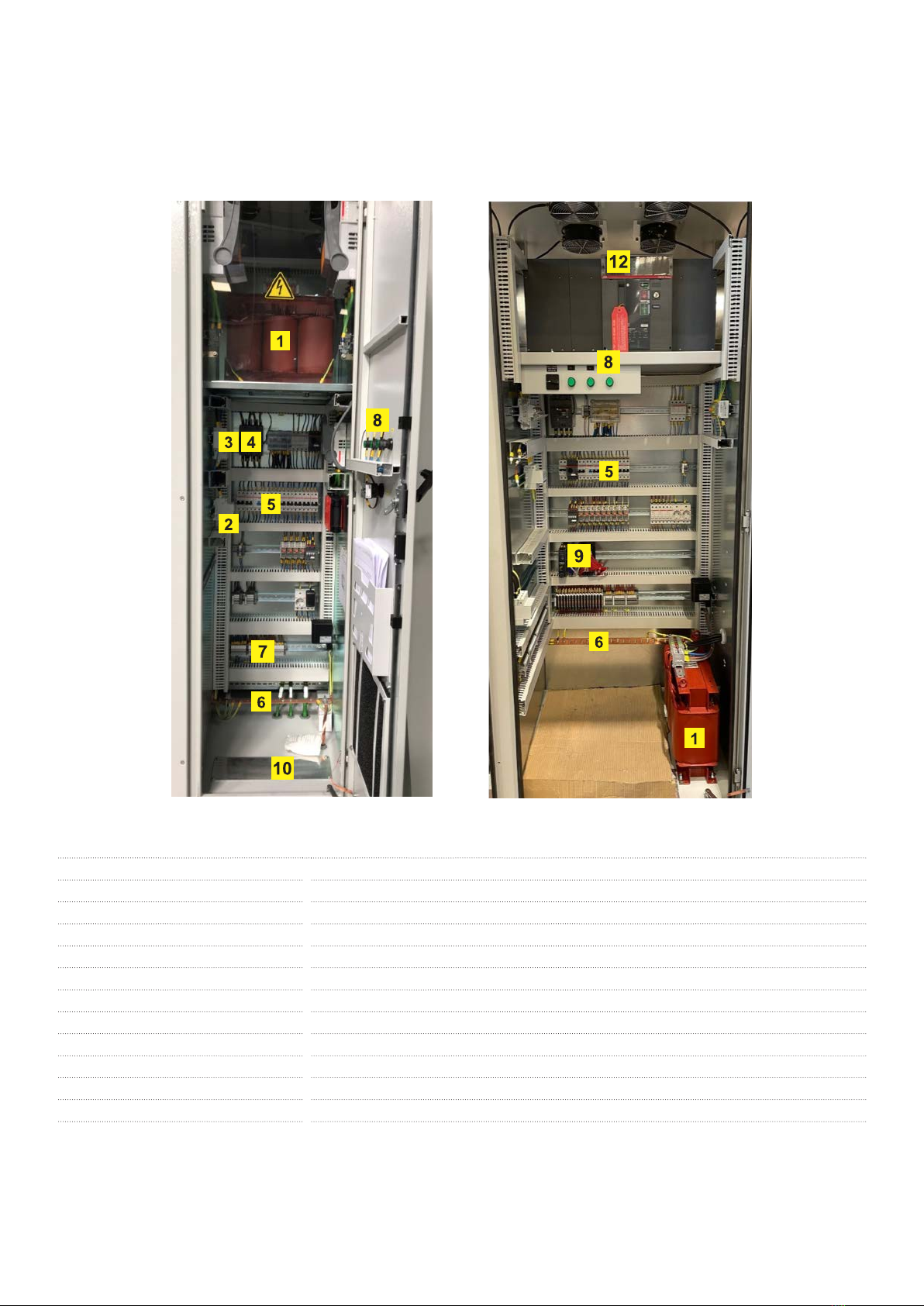
1Auxiliary service transformer
2Surge arrester protection for the auxiliary service board
3Upstream on-load fuse switch for auxiliary service transformer protection
4Downstream circuit breaker for auxiliary service transformer protection
5Auxiliary service board circuit breakers and differential protections
6Grounding busbar
7Terminals block
8Voltage presence indication LEDs
9Communication board (if present)
10 Cover for incoming cables
11 Main Circuit Breaker (if present)
12 Ventilation system
*This layout may vary depending on final MVCS configuration
Auxiliary service board (B)
The figure below shows the disposition of the main components of a standard auxiliary service board.
3 - Hardware desription
19
List of signals
Signals from the different devices described above are concentrated in the auxiliary service board (7 & 9). These digital signals are
connected to a Modbus TCP fieldbus coupler + industrial ethernet switch, so it can be integrated with an external SCADA. The list of most
common signals:
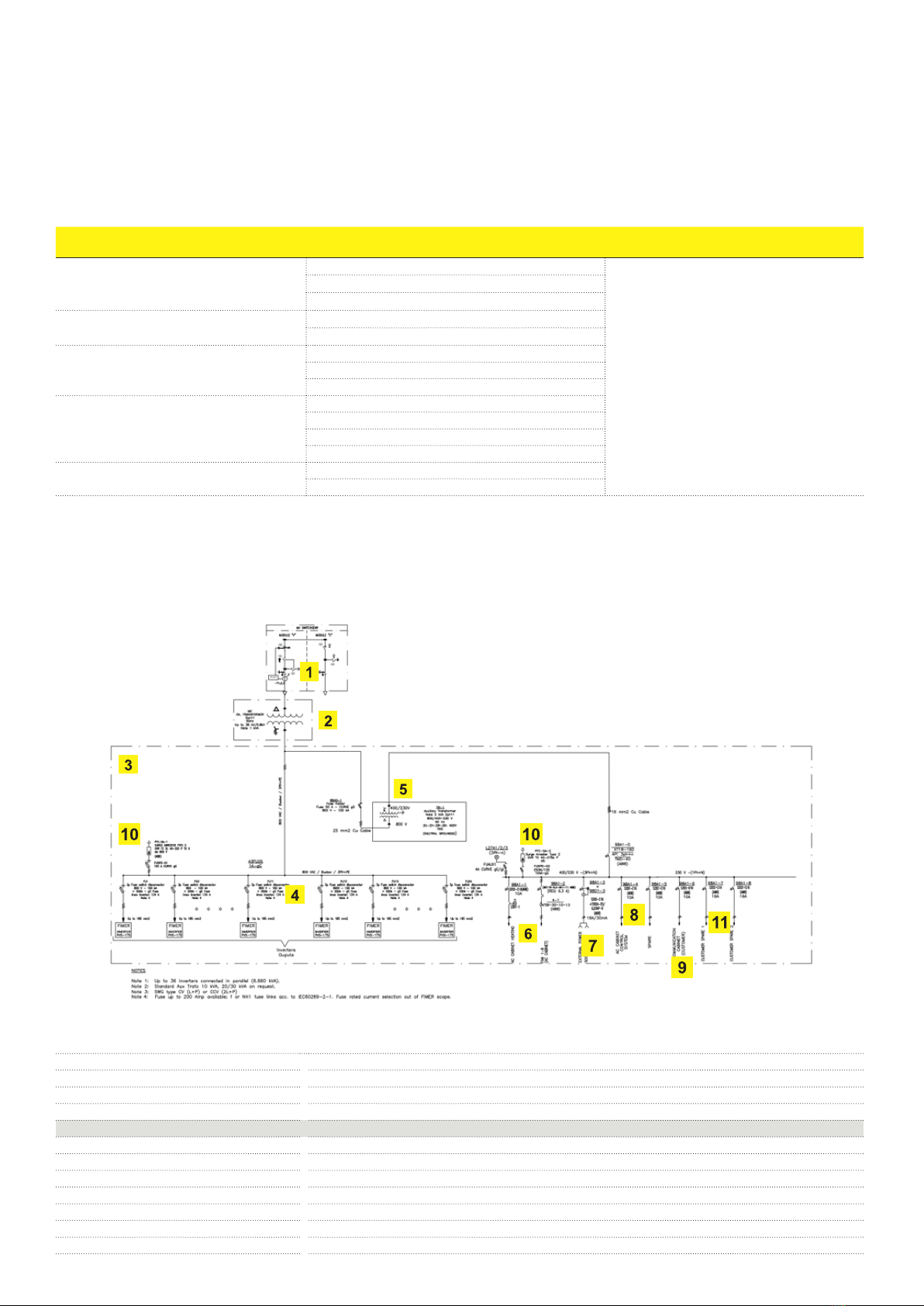
Main circuit diagram
The general single-line diagram depends on the configuration and options of the unit as well as the configuration of the inverter group. The
table below describes the baseline configuration.
Component Signal Signal type
A01 MV Cabinet type "C"
Disconnector Status
DI
Earth Switch Status
Gas Pressure Level
A02 MV Cabinet type "C" Disconnector Status
Earth Switch Status
A03 MV Cabinet type "V"
Disconnector open indication
Earth Switch open indication
Circuit Breaker Status
Oil Transformer (DGPT2/RIS2)
Temperature stop T2
Temperature stop T1
Internal Pressure alarm
Gas
Auxiliary Services Cabinet Aux Transformer secondary breaker status
Ventilation Status
*A02 MV Cabinet type “C” only for MVSWG CCV (2L+P) type
*Optionals, such as main circuit breaker, UPS, LV energy measurement; are not shown in this SLD
1MV Switchgear
2MV Transformer
3AC Cabinet
4Inverter Inputs
Auxiliary Service Board
5Auxiliary Service Transformer
6AC cabinet own loads (fans & heating)
7Sockets (1PH)
8Control
9Communication
10 SPD
11 Spares
3 - Hardware desription
20
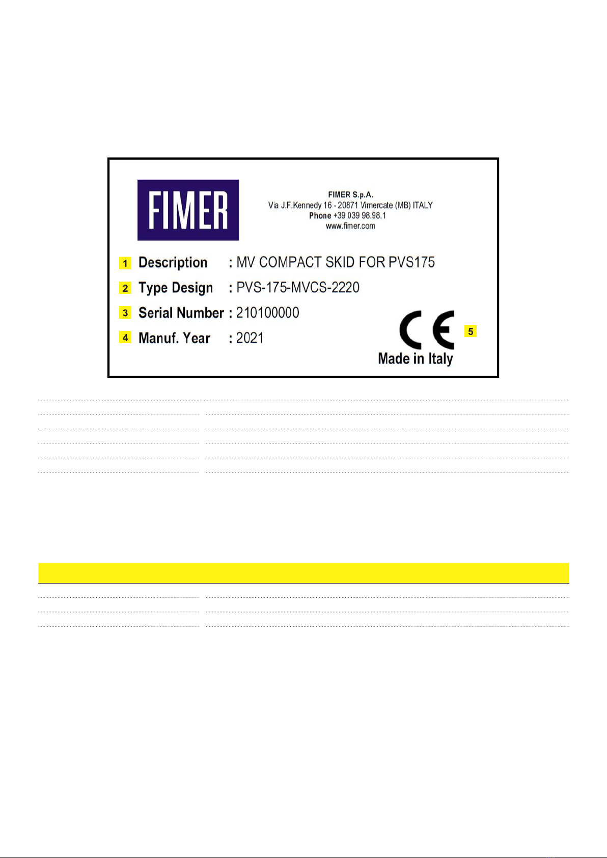
Type designation label
The figure below shows an example of the type designation label. The label contains the basic data of the unit. It is located inside the AC
cabinet, specifically in auxiliary service board section.
MVCS Configuration
To define a MVCS the following inputs are needed:
Eg:
• String Inverter: PVS-175
• Number of inverters connected to the MVCS: 20
• Medium Voltage Level: 15 kV
With the definition of the inputs above, then a standard MVCS will be configured:
• Skid: C4;
• SWG: 24kV;16kA;CV; 50/51-50N/51N-68 Relay;
• MV Transformer: 15/0,8 Dyn11; 3.700 kVA @30ºC; Losses acording EU 548/2014 Regulation
• AC Cabinet: 20 inputs;10kVA Auxtrafo (0,8/0,4-0,23 kV)
If additional features are needed, then the appropriate optional codes from the following section must be selected:
1Product description: MVCS + string inverter name
2General designation: string inverter name + MVCS rated power
3S/N
4Manufacturing Year
5CE marking
Input Value
String Inverter
Number of inverters connected
Medium Voltage level
3 - Hardware desription
Table of contents
Other Fimer Industrial Equipment manuals


