Fimer PVS-50-TL User manual

Product Manual
PVS-50-TL / PVS-60-TL
(from 50 to 60 kW)

2
000855CG-F
IMPORTANT SAFETY INSTRUCTIONS
This manual contains important safety instructions that must be followed during the installa-
tion and maintenance of the equipment.
SAVE THESE INSTRUCTIONS!
Keep this document in a safe place near the inverter for easy access during installation, op-
eration and maintenance.
THE INSTALLER MUST READ THIS DOCUMENT IN ITS ENTIRETY BEFORE INSTALLING
THIS EQUIPMENT.
Operators are required to read this manual and scrupulously follow the instructions given in it,
since FIMER cannot be held responsible for damage caused to people and/or things, or the
equipment, if the conditions described below are not observed.
The purpose of this document is to support the qualied technician, who has received training
and/or has demonstrated skills and knowledge in construction, to install, operate and maintain
the inverter. This manual covers only inverter, not any equipment (photovoltaic modules, external
disconnects, etc) to which it is connected.
Warranty requirements are included in the Terms and Conditions of sale included with the
inverter order.
NOTE: Any changes not approved by FIMER void the warranty.

3
000855CG-F
Product manual
PVS-50/60-TL string inverters
1 - Introduction and general information
2 - Characteristics
3 - Safety and accident prevention
4 - Lifting and transport
5 - Installation
6 - Instruments
7 - Operation
8 - Maintenance
9 - Attachments
FIMER-PVS-50_60-TL-Product manual EN-Rev C (M000043CG)
EFFECTIVE 30/07/2020
© Copyright 2020 FIMER. All Rights Reserved.

4
000856CG-F
1 - Introduction and general information
Table of Contents
Table of Contents....................................................................................................................................4
Introduction and general information............................................................................................... 8
Warranty and supply conditions...........................................................................................................8
Not included in the supply.......................................................................................................8
Scope and target audience....................................................................................................................9
Purpose and document structure ...........................................................................................9
List of appendix documents ....................................................................................................9
Operator and maintenance personnel skills/prerequisites .....................................................9
Symbols and signs...............................................................................................................................10
Characteristics .................................................................................................................................. 12
General conditions ...............................................................................................................................12
Field of use, general conditions ........................................................................................................13
Intended or allowed use........................................................................................................13
Limits in field of use...............................................................................................................13
Improper or prohibited use ...................................................................................................13
Identification of the equipment and manufacturer ................................................................14
Communication identification label .......................................................................................16
Models and range of equipment .........................................................................................................17
List of main reference components ...................................................................................................18
Mounting bracket ..................................................................................................................18
Inverter external view (top and rear sides) ...........................................................................18
Inverter external view (front, left, right and bottom sides) ....................................................19
Inverter internal view (wiring boxes) .....................................................................................20
Communication and control board........................................................................................21
Principal wiring box components .........................................................................................22
Characteristics and technical data.....................................................................................................23
Tightening torques ................................................................................................................27
Cable gland clamping range .................................................................................................27
Overall dimensions ...............................................................................................................28
Dimensions of mouting bracket. ...........................................................................................29
Efficiency curves ..................................................................................................................................30
Power limitation (Power Derating)......................................................................................................31
Power reduction due to environmental conditions................................................................31
Power reduction due to the input voltage .............................................................................32
Power reduction due to the grid voltage ...............................................................................32
P- Q curve capability.............................................................................................................33
Characteristics of a photovoltaic generator......................................................................................34
Strings and arrays.................................................................................................................34
Description of the equipment..............................................................................................................35
Operating diagram ................................................................................................................35
Mutual connection of multiple inverters ................................................................................36
Notes on the system sizing...................................................................................................36
Functionality and components of the equipment ............................................................................37

5
000856CG-F
1 - Introduction and general information
Highlights ..............................................................................................................................37
Improved commissioning and maintenance.........................................................................37
Aurora Vision®Plant Management Platform.........................................................................37
Configurable relay.................................................................................................................39
Remote switch-on/switch-off.................................................................................................39
Reactive power feed into the grid .........................................................................................39
Limiting the active power fed into the grid ............................................................................39
Overvoltage surge arrester monitoring .................................................................................39
Data transmission and control ..............................................................................................39
Communication connection diagrams...............................................................................................40
Communication interface ......................................................................................................40
Accessing to web server.......................................................................................................40
Ethernet bus connection .......................................................................................................41
Topographic diagram of the equipment ................................................................................42
Safety devices.......................................................................................................................................44
Anti-Islanding ........................................................................................................................44
Ground fault of the photovoltaic panels ................................................................................44
String fuses ...........................................................................................................................44
Overvoltage surge arresters .................................................................................................44
Other safeguards ..................................................................................................................44
Safety and accident prevention ...................................................................................................... 45
Safety information and instructions ..................................................................................................45
Hazardous areas and operations .......................................................................................................46
Environmental conditions and risks ......................................................................................46
Signs and labels....................................................................................................................46
Thermal and electrical hazard ..............................................................................................47
Clothing and protection of personnel....................................................................................47
Residual risks .......................................................................................................................................48
Table of residual risks ...........................................................................................................48
Lifting and transport......................................................................................................................... 49
General conditions ...............................................................................................................................49
Transport and handling .......................................................................................................49
Lifting.....................................................................................................................................49
Unpacking and checking ......................................................................................................49
Storage..................................................................................................................................50
Weight of the equipment.......................................................................................................50
Types of lifting .......................................................................................................................50
List of components supplied .................................................................................................51
Installation ......................................................................................................................................... 52
General conditions ...............................................................................................................................52
Installation site and position..................................................................................................53
Wireless signal environmental checks..................................................................................55
Installations above 2000 metres...........................................................................................56
Installations with a high level of humidity .............................................................................56
Mounting of the inverter on the bracket ............................................................................................57
Grid output connection (AC side).......................................................................................................60

6
000856CG-F
1 - Introduction and general information
Characteristics and sizing of the protective earth cable.......................................................60
Installation of the second protective earthing cable .............................................................61
Residual current protection device .......................................................................................61
Load protection switch (AC disconnect switch) ....................................................................61
Characteristics and sizing of the line cable ..........................................................................62
Connection to terminal block AC side...................................................................................63
Operations preliminary to the connection of the PV generator......................................................66
Checking of leakage to ground of the photovoltaic generator..............................................66
Checking of strings voltage...................................................................................................66
Checking the correct polarity of the strings .........................................................................66
Independent or parallel input channels configuration.....................................................................67
Channel configuration examples ..........................................................................................68
Independent channel configuration (default configuration) ..................................................69
Parallel channel configuration ..............................................................................................69
Input connection to PV generator (DC side) .....................................................................................70
Connection of inputs on the Standard and -S models..........................................................71
Connection of inputs on the -SX / -SX2 models ...................................................................72
Installation procedure for quick-fit connectors ......................................................................73
String protection fuses (-SX / -SX2 models only) .............................................................................77
Sizing of fuses.......................................................................................................................77
Communication and control board ....................................................................................................79
Connections to the communication and control board...................................................................80
Ethernet connection ..............................................................................................................81
Serial Communication connection - Slave (RS485-1, RS485-2) .........................................83
Serial Communication connection - Slave/Master (RS485-MAIN) ......................................86
Remote control connection ...................................................................................................87
Configurable Relay connection (ALARM and AUX) .............................................................87
Front cover closure ..............................................................................................................................88
Instruments........................................................................................................................................ 89
General conditions ..............................................................................................................................89
Description of the LED function .........................................................................................................90
LED isolation fault .................................................................................................................90
User interface........................................................................................................................................91
Measurement tolerance ........................................................................................................91
Operation ........................................................................................................................................... 92
General conditions ..............................................................................................................................92
Commissioning.....................................................................................................................................93
Commissioning via Installer for Solar Inverters mobile APP ................................................94
Commissioning Via Web UI - Wireless connection ..............................................................98
LED behaviour ....................................................................................................................................106
Description of the Web User Interface.............................................................................................108
Access to the Web User Interface ......................................................................................108
Web User Interface menu structure.................................................................................... 111
MAIN section.......................................................................................................................112
SETTING section ................................................................................................................113
Inverter Log ........................................................................................................................117
USER section......................................................................................................................118

7
000856CG-F
1 - Introduction and general information
NETWORK Services ..........................................................................................................119
Service TOOLS ..................................................................................................................126
INFORMATION ..................................................................................................................132
Inverter switch-off...............................................................................................................................133
Operator and maintenance personnel skills/prerequisites .................................................133
Switch-off procedure ...........................................................................................................134
Maintenance .................................................................................................................................... 140
General conditions .............................................................................................................................140
Routine maintenance .........................................................................................................141
Troubleshooting .................................................................................................................................142
Internal Webserver and wireless communication troubleshooting.....................................142
Alarm Messages of the Inverter..........................................................................................144
Power limitation messages .................................................................................................156
Procedure for dismantling the Inverter ...........................................................................................158
Registration on “Registration” website and calculation of security token (Admin Plus) .........159
Replacing DC string fuses.................................................................................................................162
Replacing cooling section.................................................................................................................163
Replacement of the buffer battery....................................................................................................164
Verification of ground leakage .........................................................................................................165
Behaviour of a system without leakage ..............................................................................165
Behaviour of a system with leakage ...................................................................................166
Measuring the isolation resistance of the PV generator................................................................167
Storage and dismantling ..................................................................................................................168
Storage of the equipment or prolonged stop ......................................................................168
Dismantling, decommissioning and disposal......................................................................168
Attachments .................................................................................................................................... 169
Port and network services used by the inverter.............................................................................169
IP Network Services............................................................................................................169
Network Hosts.....................................................................................................................170
Inverter network configuration ............................................................................................170
Contact us ...........................................................................................................................................171

8
000002FG-F
Warranty and supply conditions
The warranty conditions are considered to be valid if the Customer adhe-
res to the indications in this manual; any conditions deviating from those
described herein must be expressly agreed in the purchase order.
FIMER declares that the equipment complies with the provisions of law currently in force in
the country of installation and has issued the corresponding declaration of conformity.
Not included in the supply
FIMER accepts no liability for failure to comply with the instructions for correct installation
and will not be held responsible for systems upstream or downstream of the equipment it has
supplied.
It is absolutely forbidden to modify the equipment. Any modication, manipulation, or alte-
ration not expressly agreed with the manufacturer, concerning either hardware or software,
shall result in the immediate cancellation of the warranty.
The customer is fully responsible for any changes made to the system.
Given the countless array of system congurations and installation envi-
ronments possible, it is essential to check the following: adequate spa-
ces, suitable for housing the equipment; airborne noise produced based
on the environment; possible ammability conditions.
FIMER will NOT be held liable for defects or malfunctions arising from:
improper use of the equipment; deterioration resulting from transporta-
tion or particular environmental conditions; performing maintenance in-
correctly or not at all; tampering or unsafe repairs; use or installation by
unqualied persons.
FIMER is not responsible for any loss of the equipment, or part of it,
which does not take place on the basis of the regulations and laws in
force in the country of installation.
1
Introduction and general information
9
000883AG-F
1- Introduction and general information
Scope and target audience
Purpose and document structure
This operating and maintenance manual is a useful guide that will enable
you to work safely and carry out the operations necessary for keeping the
equipment in good working order.
If the equipment is used in a manner not specied in this manual, the protection provided by
the equipment may be impaired.
The language in which the document was originally written is ENGLISH; therefore, in the event
of inconsistencies or doubts please ask the manufacturer for the original document.
List of appendix documents
In addition to this user manual and maintenance you can consult (and
download) the product documentation by visiting www.mer.com.
Part of the information given in this document is taken from the original supplier documents.
This document contains only the information considered necessary for the use and routine
maintenance of the equipment.
Operator and maintenance personnel skills/prerequisites
Personnel in charge of using and maintaining the equipment must be skilled for the described
tasks and must reliably demonstrate their capacity to correctly interpret what is described in
the manual.
For safety reasons, only a qualied electrician who has received training and/or demonstrated
skills and knowledge of the inverter’s structure and operation may install the inverter.
The installation must be performed by qualied installers and/or licensed electricians in accor-
dance with the existing regulations in the country of installation and in accordance of all safety
rules for performing electrical works.
Inverter operation and maintenance by a person who is NOT qualied, is intoxicated, or on
narcotics, is strictly forbidden.
The customer has civil liability for the qualication and mental or physical state of the person-
nel who interact with the equipment. They must always use the personal protective equipment
(PPE) required by the laws of the country of destination and whatever is provided by their
employer.
10
000006HG-F
1 - Introduction and general information
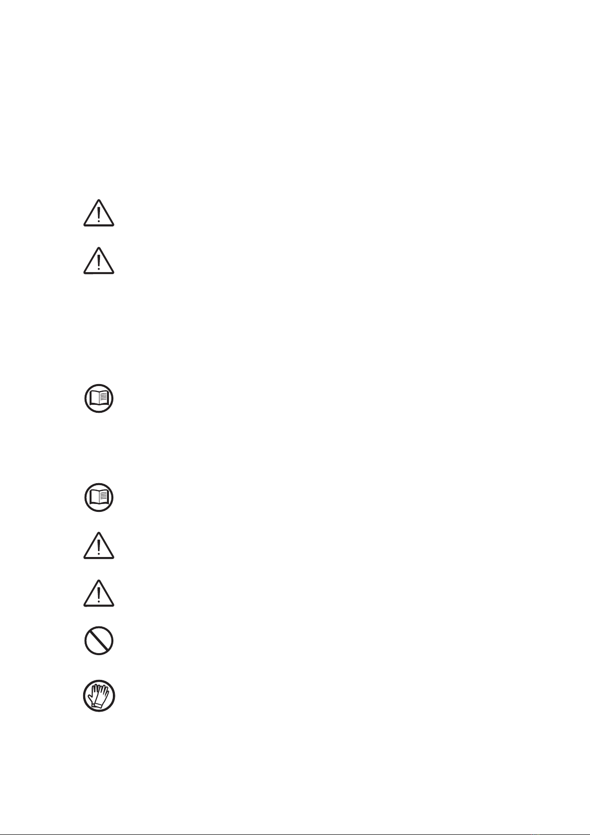
Symbols and signs
In the manual and/or in some cases on the equipment, the danger or
hazard zones are indicated with signs, labels, symbols or icons.
Symbol Description
Indicates that it is mandatory to consult the manual or original document,
which must be available for future use and must not be damaged in any
way.
General warning - Important safety information. Indicates operations or
situations in which staff must be very careful.
Dangerous Voltage - Indicates operations or situations in which staff
must be very careful with regard to dangerous voltage levels.
Hot parts - Indicates a risk arising from the presence of hot zones or
zones with parts at high temperatures (risk of burns).
Risk of explosion
Risk of injury due to the weight of the equipment. Take care during lifting
and transport
Indicates that the area in question must not be accessed or that the ope-
ration described must not be carried out.
Keep out of the reach of children
Indicates that smoking and the use of naked ames is prohibited.
Indicates that it is mandatory to carry out the described operations using
theclothing and/or personal protective equipment provided by the em-
ployer.
WEEE logo. Indicates that the product is to be disposed of according to
current legislation regarding the disposal of electronic components.
IPXX Indicates the protection rating of the equipment according to IEC 70-1
(EN 60529 June 1997) standard.
Point of connection for grounding protection.
Indicates the permitted temperature range
11
000006HG-F
1 - Introduction and general information
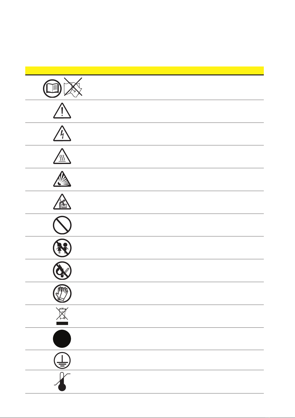
Symbol Description
XX
Risk of electric shock.The discharge time (quantied in the gure by the
number XX) of the stored energy after de-energizing of the Inverter from
both DC side and AC side.
DC
Direct Current
AC
Alternate current
With isolation transformer
Without isolation transformer
Positive pole of the input voltage (DC)
Negative pole of the input voltage (DC)
Indicates the centre of gravity of the equipment.
Indicates the requirement to wear acoustic protection devices in order to
prevent damage to hearing

12
000008EG-F
General conditions
A description of the equipment characteristics is provided to identify its
main components and specify the technical terminology used in the ma-
nual.
This chapter contains information about the models, details of the
equipment, characteristics and technical data, overall dimensions and
equipment identication.
The customer/Installer takes full responsibility if, when reading this manual, the chronological
order of its presentation provided is not observed. All information is provided considering
occasional inclusion of information in previous chapters.
In certain cases, there may be a need to separately document softwa-
re functionality or attach supplementary documentation to this manual
which is intended for more qualied professionals.
2
Characteristics

13
000007CG-F
1- Introduction and general information
Field of use, general conditions
FIMER shall not be liable for any damages whatsoever that may result
from incorrect or careless operations.
You may not use the equipment for a use that does not conform to that provided for in the
eld of use. The equipment MUST NOT be used by inexperienced staff, or even experienced
staff if carrying out operations on the equipment that fail to comply with the indications in this
manual and enclosed documentation.
Intended or allowed use
This equipment is a inverter designed for:
transforming a continuous electrical current (DC)
supplied by a photovoltaic generator (PV)
in an alternating electrical current (AC)
suitable for feeding into the public distribution grid.
Limits in field of use
The inverter can be used only with photovoltaic modules which have ground isolated input
poles, unless they are accessories installed that enable earthing of the inputs. In this case
you must install an insulating transformer on the AC side of the system.
Only a photovoltaic generator can be connected in the input of the inverter (do not connect
batteries or other sources of power supply).
The inverter can be connected to the electricity grid only in countries for which it has been
certied/approved.
The inverter cannot be connected to the DC side in parallel to other inverters to convert ener-
gy from a photovoltaic generator with a power greater than the nominal power of the single
inverter.
The inverter may only be used in compliance with all its technical characteristics.
Improper or prohibited use
IT IS STRICTLY FORBIDDEN TO:
• Install the equipment in environments subject to particular conditions of ammability or in
adverse or disallowed environmental conditions, (temperature and humidity).
• Use the equipment with safety devices which are faulty or disabled.
• Use the equipment or parts of the equipment by linking it to other machines or equipment,
unless expressly provided for.
• Modify operating parameters that are not accessible to the operator and/or parts of the
equipment to vary its performance or change its isolation.
• Clean with corrosive products that could eat into parts of the equipment or generate elec-
trostatic charges.
• Use or install the appliance or parts of it without having read and understood the contents of
the user and maintenance manual.
• Heat or dry rags and clothing on the parts in temperature. In addition to being hazardous,
doing so would compromise component ventilation and cooling.
14
000857BG-F
2 - Characteristics
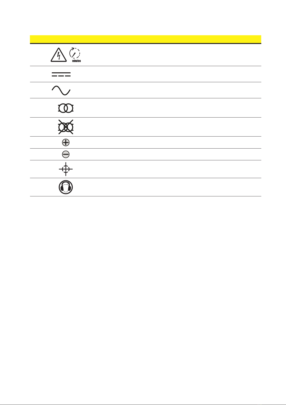
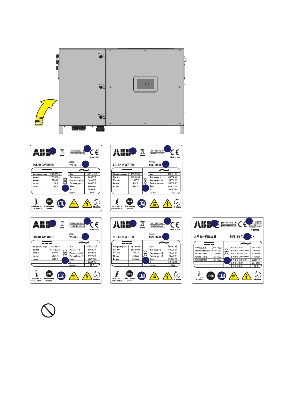
The approval label contains the
following information:
1. Manufacturer
2. Model
3. Rating data
4. Certication marks
Identification of the equipment and manufacturer
The technical data provided in this manual does not substitute the data
supplied on the labels afxed to the equipment.
The labels afxed to the equipment must NOT be removed, damaged, stained, hidden, etc.,
for any reason whatsoever.
PVS-50-TL:
The labels are NOT to be hidden by foreign objects and parts (rags, boxes, equipment, etc.);
they must be regularly cleaned and always kept in sight.
PVS-60
POWER ALARM GFI
14
2
3
14
2
3
14
2
3
14
2
3
15
000857BG-F
2 - Characteristics
The approval label contains the
following information:
1. Manufacturer
2. Model
3. Rating data
4. Certication marks
The labels are NOT to be hidden by foreign objects and parts (rags, boxes, equipment, etc.);
they must be regularly cleaned and always kept in sight.
PVS-60
POWER ALARM GFI
PVS-60-TL:
14
2
3
14
2
3
14
2
3
14
2
3
14
2
3

16
000857BG-F
2 - Characteristics
In addition to the label showing the inverter data, there is an additional
identication label for the inverter.
The label displays the following information:
The ofcially required information is located on the approval label. The identication label
is an accessory label which shows the information necessary for the identication and cha-
racterisation of the inverter by FIMER.
The labels are NOT to be hidden by foreign objects and parts (rags, boxes, equipment, etc.);
they must be regularly cleaned and always kept in sight.
Communication identification label
An additional Communication Identication label is applied on the wiring
box. The label displays the following information:
The Communication Identication label is divided in two separate parts by a dashed line; take
the bottom part and apply it on the plant documentation. (it’s recommend to create a plant
map and apply the Communication Identication label of each inverters in the right position
of that map).
• Inverter model
• Inverter Part Number
• Inverter Serial Number consisting of:
- YY = Year of manufacture
- WW = Week of manufacture
- SSSSSS = sequential number
• Week/Year of manufacture
• Manufacturer
MODEL NAME
POWER-ONE ITALY S.p.A
Via S.Giorgio 642, Terranuova Bracciolini (AR), 52028, Italia
P/N:PPPPPPPPPPP
WO:XXXXXXX
SO:SXXXXXXXX Q1
SN:YYWWSSSSSS WK:WWYY
SN WLAN: SSSSSSSSSS
PN WLAN: PPP.PPPPP.PP
Mac Address:
XX:XX:XX:XX:XX:XX
SN WLAN: SSSSSSSSSS
SN Inverter: SSSSSSSSSS
MAC: XX:XX:XX:XX:XX:XX
PK: KKKK-KKKK-KKKK-KKKK
Remove and apply on the Quick installaon guide
• WLAN board Serial Number
• WLAN board Part Number
• Inverter Serial Number
• MAC address:
- To be used to obtain the SSID of the wireless access point
created by the inverter: ABB-XX-XX-XX-XX-XX-XX
(where “X” is a hex digit of the MAC address).
- To be used to obtain the “Host Name”:
http:// -XX-XX-XX-XX-XX-XX.local
(where “X” is a hex digit of the MAC address).
- MAC address it’s the only required information to register the
inverter with Aurora Vision.
• Product Key:
To be used as wireless access point password, or to be used to
access to the Web UI as username and password in case of lost
credentials, and to commission inverter using FIMER Installer for
Solar Inverters.

17
000857BG-F
2 - Characteristics
Models and range of equipment
The choice of the inverter model must be made by a qualied technician
who knows about the installation conditions, the devices that will be installed
outside the inverter and possible integration with an existing system.
The models of three-phase inverters covered by this manual are divided
into two groups according to their maximum output power:
50kW and 60kW.
For each model, the following variants are available.
Inverter
Model Number Description
PVS-50-TL
PVS-60-TL
• DC Terminal blocks. Single MPPT
• AC Terminal blocks
• SPD type II in both sides AC and DC monitored
PVS-50-TL-S
PVS-60-TL-S
• DC Switch
• DC Terminal blocks. Single MPPT
• AC Terminal blocks
• SPD type II in both sides AC and DC monitored
PVS-50-TL-SX
PVS-60-TL-SX
• 15 DC input via fast connectors
• 3 independent MPPT(parallel has to be possible)
• Protection fuses on POSITIVE pole only (state monitoring not included)
• DC Switch
• SPD type II in both sides AC and DC monitored
PVS-60-TL-SX-CN
• 12 DC input via fast connectors
• 3 independent MPPT (parallel has to be possible)
• Protection fuses on POSITIVE pole only (state monitoring not included)
• DC Switch
• SPD type II in both sides AC and DC monitored
PVS-50-TL-SX2*
PVS-60-TL-SX2*
• 15 DC input via fast connectors
• 3 independent MPPT (parallel has to be possible)
• Protection fuses on both poles (state monitoring not included)
• DC Switch
• SPD type II in both sides AC and DC monitored
All inverter models can be equipped with display by dedicated part number (“;DISPLAY” sufx)
* The SX2 versions can be equipped with SPD type I e II in DC side monitored by dedicated
part number (“;SPD1+2” sufx)
18
000858BG-F
2 - Characteristics
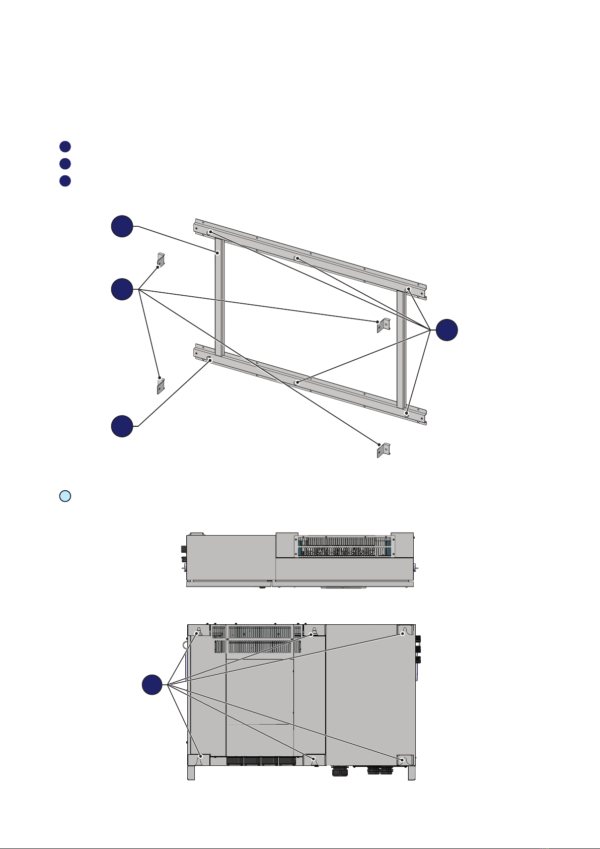
List of main reference components
Mounting bracket
01 Mounting bracket
02 Locking brackets
03 Inverter/bracket anchor points
Inverter external view (top and rear sides)
03 Inverter/bracket anchor points
OFF
ON
OUTPUT AC
INPUT DC
OUTPUT AC
INPUT DC
OUTPUT AC
INPUT DC
INPUT DC
1A
1B
1C
1D
2A
2B
2C
2D
3A
3B
3C
3D
PVS-60
INPUT DC
1A
1B
1C
1D
1E
2A
2B
2C
2D
2E
3A
3B
3C
3D
3E
16
11
09
14
11
24
17
10
15
09
14
12
13
11
24
PVS-50/60-TL
PVS-50/60-TL-S
PVS-50/60-TL-SX
PVS-50/60-TL-SX2
PVS-60-TL-SX-CN
04 05
08070605
18 23
22
18
21
20
19
23
22
18
21
20
19
23
22
03
11
01
03
02
03
19
000858BG-F
2 - Characteristics
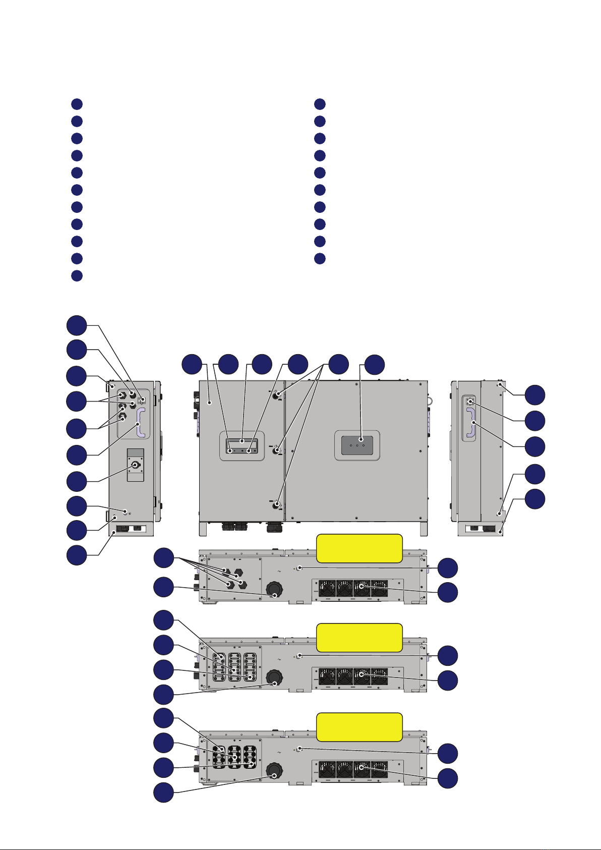
Inverter external view (front, left, right and bottom sides)
04 Wiring box front door 15 DC disconnect switch
05 LED panel 16 Protective earth terminal (external)
06 Display 17 DC cable glands
07 Keypad 18 AC cable gland
08 Key lock 19 Input quick t connectors (channel 1)
09 Lifting ring 20 Input quick t connectors (channel 2)
10 Wi-Fi antenna connector 21 Input quick t connectors (channel 3)
11 Locking brackets attachment point 22 Anti-condensation valve
12 Ethernet cable gland 23 Cooling section
13 Service cable gland 24 Lower support
14 Handle
OFF
ON
OUTPUT AC
INPUT DC
OUTPUT AC
INPUT DC
OUTPUT AC
INPUT DC
INPUT DC
1A
1B
1C
1D
2A
2B
2C
2D
3A
3B
3C
3D
PVS-60
INPUT DC
1A
1B
1C
1D
1E
2A
2B
2C
2D
2E
3A
3B
3C
3D
3E
16
11
09
14
11
24
17
10
15
09
14
12
13
11
24
PVS-50/60-TL
PVS-50/60-TL-S
PVS-50/60-TL-SX
PVS-50/60-TL-SX2
PVS-60-TL-SX-CN
04 05
08070605
18 23
22
18
21
20
19
23
22
18
21
20
19
23
22
03
11

20
000858BG-F
2 - Characteristics
Inverter internal view (wiring boxes)
30 communication and control board 36 AC overvoltage surge arresters
31 Grounding kit (optional kit) 37 Protective earth terminal (internal)
32 DC overvoltage surge arresters 38 AC output screw terminal block
33 DC disconnect switch 39 DC input screw terminal block
34 Negative (-) side string fuses 40 AC lter board
35 Positive (+) side string fuses 41 Parallel MPPT connection points
30
31
32
33
38
40
37
PVS-50-TL-SX
PVS-60-TL-SX
PVS-60-TL-SX-CN 30
31
32
33
38
40
37
PVS-50-TL-SX2
PVS-60-TL-SX2
35 35
34
41 4141
36 3636
PVS-50-TL
PVS-60-TL
30
31
32
39
38
40
37
PVS-50-TL-S
PVS-60-TL-S
30
31
32
33
39
38
40
37
3636
Other manuals for PVS-50-TL
1
This manual suits for next models
1
Table of contents
Other Fimer Industrial Equipment manuals

Popular Industrial Equipment manuals by other brands

PCB Piezotronics
PCB Piezotronics 052M96A Installation and operating manual

ABB
ABB HT608065 Operation manual

C.P.Bourg
C.P.Bourg Document Finisher E Series Operator's manual

DANA
DANA SPICER AXLE 212 Service manual

GÜDE
GÜDE GSS 500 Translation of the original instructions

Tyco Electronics
Tyco Electronics AMP-O-LECTRIC 690675-2 instruction sheet


