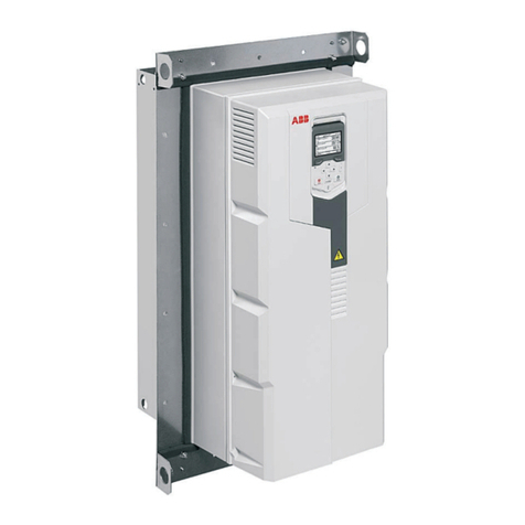
ABB RELION 650 SERIES Instructions for use

Relion® 650 SERIES
Busbar protection REB650
Version 1.3 ANSI
Application manual


Document ID: 1MRK 505 287-UUS
Issued: November 2019
Revision: B
Product version: 1.3
© Copyright 2013 ABB. All rights reserved

Copyright
This document and parts thereof must not be reproduced or copied without written permission
from ABB, and the contents thereof must not be imparted to a third party, nor used for any
unauthorized purpose.
The software and hardware described in this document is furnished under a license and may be
used or disclosed only in accordance with the terms of such license.
This product includes software developed by the OpenSSL Project for use in the OpenSSL Toolkit.
(http://www.openssl.org/)
This product includes cryptographic software written/developed by: Eric Young
([email protected]) and Tim Hudson ([email protected]).
Trademarks
ABB and Relion are registered trademarks of the ABB Group. All other brand or product names
mentioned in this document may be trademarks or registered trademarks of their respective
holders.
Warranty
Please inquire about the terms of warranty from your nearest ABB representative.
ABB AB
Grid Automation Products
SE-721 59 Västerås
Sweden
Telephone: +46 (0) 21 32 50 00
Facsimile: +46 (0) 21 14 69 18
http://www.abb.com/protection-control

Disclaimer
The data, examples and diagrams in this manual are included solely for the concept or product
description and are not to be deemed as a statement of guaranteed properties. All persons
responsible for applying the equipment addressed in this manual must satisfy themselves that
each intended application is suitable and acceptable, including that any applicable safety or other
operational requirements are complied with. In particular, any risks in applications where a system
failure and/or product failure would create a risk for harm to property or persons (including but
not limited to personal injuries or death) shall be the sole responsibility of the person or entity
applying the equipment, and those so responsible are hereby requested to ensure that all
measures are taken to exclude or mitigate such risks.
This document has been carefully checked by ABB but deviations cannot be completely ruled out.
In case any errors are detected, the reader is kindly requested to notify the manufacturer. Other
than under explicit contractual commitments, in no event shall ABB be responsible or liable for any
loss or damage resulting from the use of this manual or the application of the equipment.

Conformity
This product complies with the directive of the Council of the European Communities on the
approximation of the laws of the Member States relating to electromagnetic compatibility (EMC
Directive 2004/108/EC) and concerning electrical equipment for use within specified voltage
limits (Low-voltage directive 2006/95/EC). This conformity is the result of tests conducted by ABB
in accordance with the product standards EN 50263 and EN 60255-26 for the EMC directive, and
with the product standards EN 60255-1 and EN 60255-27 for the low voltage directive. The product
is designed in accordance with the international standards of the IEC 60255 series and ANSI
C37.90.

Table of contents
Section 1 Introduction........................................................................................................11
1.1 This manual......................................................................................................................................... 11
1.2 Intended audience............................................................................................................................. 11
1.3 Product documentation...................................................................................................................12
1.3.1 Product documentation set.......................................................................................................... 12
1.3.2 Document revision history............................................................................................................ 13
1.3.3 Related documents.........................................................................................................................13
1.4 Symbols and conventions................................................................................................................14
1.4.1 Symbols.............................................................................................................................................14
1.4.2 Document conventions..................................................................................................................14
Section 2 Application..........................................................................................................17
2.1 REB650 application........................................................................................................................... 17
2.2 Available functions............................................................................................................................18
2.2.1 Main protection functions.............................................................................................................18
2.2.2 Back-up protection functions.......................................................................................................19
2.2.3 Control and monitoring functions...............................................................................................19
2.2.4 Station communication................................................................................................................. 23
2.2.5 Basic IED functions.........................................................................................................................24
2.3 REB650 application examples........................................................................................................ 25
2.3.1 Adaptation to different applications..........................................................................................25
2.3.2 Protection of a two section busbar with additional bus coupler protection functions.. 25
2.3.3 Protection of a single section busbar ........................................................................................26
2.3.4 Functionality table..........................................................................................................................26
Section 3 REB650 setting examples.................................................................................29
3.1 Busbar protection application....................................................................................................... 29
3.1.1 Calculating general settings for analogue TRM inputs 6I 4U.................................................31
3.1.2 Calculating general settings for analogue AIM inputs 6I 4U..................................................32
3.1.3 Preprocessing blocks (SMAI)........................................................................................................ 33
3.1.4 Calculating settings for global base values for setting function GBASVAL........................33
3.1.5 Calculating settings for busbar high impedance differential protection HZPDIF (87).... 33
3.1.6 Calculating settings for breaker failure protection 3-phase activation and output
CCRBRF (50BF)................................................................................................................................ 35
3.1.7 Calculating settings for pole discordance protection CCRPLD (52PD)............................... 36
Section 4 Analog inputs..................................................................................................... 37
4.1 Introduction........................................................................................................................................37
4.2 Setting guidelines............................................................................................................................. 37
Table of contents
Busbar protection REB650 1
Application manual
© Copyright 2013 ABB. All rights reserved

4.2.1 Setting of the phase reference channel..................................................................................... 37
4.2.2 Relationships between setting parameter Base Current, CT rated primary current
and minimum pickup of a protection IED.................................................................................. 37
4.2.3 Setting of current channels.......................................................................................................... 38
4.2.3.1 Example 1.................................................................................................................................... 39
4.2.3.2 Example 2....................................................................................................................................39
4.2.3.3 Examples on how to connect, configure and set CT inputs for most commonly
used CT connections.................................................................................................................41
4.2.3.4 Example on how to connect a wye connected three-phase CT set to the IED............. 42
4.2.4 Setting of voltage channels..........................................................................................................44
4.2.4.1 Example.......................................................................................................................................44
4.2.4.2 Examples how to connect, configure and set VT inputs for most commonly
used VT connections................................................................................................................ 44
4.2.4.3 Examples on how to connect a three phase-to-ground connected VT to the IED.......45
4.2.4.4 Example how to connect the open delta VT to the IED for low impedance
grounded or solidly grounded power systems................................................................... 47
Section 5 Local human-machine interface.......................................................................51
5.1 Local HMI.............................................................................................................................................51
5.1.1 Display............................................................................................................................................... 51
5.1.2 LEDs...................................................................................................................................................53
5.1.3 Keypad.............................................................................................................................................. 53
5.1.4 Local HMI functionality..................................................................................................................54
5.1.4.1 Protection and alarm indication............................................................................................ 54
5.1.4.2 Parameter management .........................................................................................................56
5.1.4.3 Front communication...............................................................................................................56
Section 6 Differential protection..................................................................................... 59
6.1 1Ph High impedance differential protection HZPDIF (87)........................................................ 59
6.1.1 Identification................................................................................................................................... 59
6.1.2 Application....................................................................................................................................... 59
6.1.2.1 The basics of the high impedance principle........................................................................60
6.1.3 Setting guidelines...........................................................................................................................64
6.1.3.1 Configuration.............................................................................................................................65
6.1.3.2 Settings of protection function............................................................................................. 65
6.1.3.3 Busbar protection..................................................................................................................... 65
6.1.3.4 Alarm level operation................................................................................................................68
6.1.3.5 Double busbar applications.................................................................................................... 69
Section 7 Current protection.............................................................................................71
7.1 Four step phase overcurrent protection 3-phase output OC4PTOC (51/67)........................71
7.1.1 Identification....................................................................................................................................71
7.1.2 Application........................................................................................................................................71
7.1.3 Setting guidelines........................................................................................................................... 72
Table of contents
2Busbar protection REB650
Application manual
© Copyright 2013 ABB. All rights reserved

7.1.3.1 Settings for steps 1 to 4 ..........................................................................................................73
7.1.3.2 2nd harmonic restrain.............................................................................................................. 75
7.2 Four step residual overcurrent protection, zero, negative sequence direction
EF4PTOC (51N/67N).........................................................................................................................80
7.2.1 Identification...................................................................................................................................80
7.2.2 Application.......................................................................................................................................80
7.2.3 Setting guidelines........................................................................................................................... 81
7.2.3.1 Settings for steps 1 and 4 .......................................................................................................82
7.2.3.2 Common settings for all steps............................................................................................... 83
7.2.3.3 2nd harmonic restrain.............................................................................................................. 85
7.3 Thermal overload protection, two time constants TRPTTR (49)............................................ 85
7.3.1 Identification................................................................................................................................... 85
7.3.2 Application....................................................................................................................................... 85
7.3.3 Setting guideline.............................................................................................................................86
7.4 Breaker failure protection 3-phase activation and output CCRBRF (50BF)..........................88
7.4.1 Identification................................................................................................................................... 88
7.4.2 Application.......................................................................................................................................88
7.4.3 Setting guidelines...........................................................................................................................89
7.5 Pole discrepancy protection CCRPLD (52PD).............................................................................. 91
7.5.1 Identification....................................................................................................................................91
7.5.2 Application....................................................................................................................................... 91
7.5.3 Setting guidelines...........................................................................................................................92
7.6 Negative sequence based overcurrent function DNSPTOC (46).............................................93
7.6.1 Identification................................................................................................................................... 93
7.6.2 Application....................................................................................................................................... 93
7.6.3 Setting guidelines...........................................................................................................................93
Section 8 Voltage protection............................................................................................ 95
8.1 Two step undervoltage protection UV2PTUV (27)..................................................................... 95
8.1.1 Identification................................................................................................................................... 95
8.1.2 Application....................................................................................................................................... 95
8.1.3 Setting guidelines...........................................................................................................................96
8.1.3.1 Equipment protection, such as for motors and generators............................................ 96
8.1.3.2 Disconnected equipment detection..................................................................................... 96
8.1.3.3 Power supply quality ............................................................................................................... 96
8.1.3.4 Voltage instability mitigation.................................................................................................96
8.1.3.5 Backup protection for power system faults........................................................................96
8.1.3.6 Settings for Two step undervoltage protection.................................................................96
8.2 Two step overvoltage protection OV2PTOV (59)....................................................................... 97
8.2.1 Identification................................................................................................................................... 98
8.2.2 Application.......................................................................................................................................98
8.2.3 Setting guidelines...........................................................................................................................98
8.3 Two step residual overvoltage protection ROV2PTOV (59N)................................................ 100
Table of contents
Busbar protection REB650 3
Application manual
© Copyright 2013 ABB. All rights reserved
8.3.1 Identification................................................................................................................................. 100
8.3.2 Application.....................................................................................................................................100
8.3.3 Setting guidelines......................................................................................................................... 101
8.3.3.1 Power supply quality...............................................................................................................101
8.3.3.2 High impedance grounded systems....................................................................................101
8.3.3.3 Direct grounded system........................................................................................................ 102
8.3.3.4 Settings for Two step residual overvoltage protection.................................................. 103
Section 9 Secondary system supervision......................................................................105
9.1 Fuse failure supervision SDDRFUF.............................................................................................. 105
9.1.1 Identification................................................................................................................................. 105
9.1.2 Application..................................................................................................................................... 105
9.1.3 Setting guidelines.........................................................................................................................106
9.1.3.1 General...................................................................................................................................... 106
9.1.3.2 Setting of common parameters...........................................................................................106
9.1.3.3 Negative sequence based......................................................................................................107
9.1.3.4 Zero sequence based..............................................................................................................107
9.1.3.5 Delta V and delta I .................................................................................................................. 108
9.1.3.6 Dead line detection.................................................................................................................108
9.2 Breaker close/trip circuit monitoring TCSSCBR.......................................................................109
9.2.1 Identification................................................................................................................................. 109
9.2.2 Application..................................................................................................................................... 109
Section 10 Control...............................................................................................................115
10.1 Synchronism check, energizing check, and synchronizing SESRSYN (25)............................115
10.1.1 Identification..................................................................................................................................115
10.1.2 Application......................................................................................................................................115
10.1.2.1 Synchronizing........................................................................................................................... 115
10.1.2.2 Synchronism check..................................................................................................................116
10.1.2.3 Energizing check...................................................................................................................... 117
10.1.2.4 Voltage selection..................................................................................................................... 118
10.1.2.5 External fuse failure.................................................................................................................119
10.1.3 Application examples...................................................................................................................120
10.1.3.1 Single circuit breaker with single busbar............................................................................121
10.1.3.2 Single circuit breaker with double busbar, external voltage selection.........................122
10.1.3.3 Single circuit breaker with double busbar, internal voltage selection......................... 123
10.1.4 Setting guidelines......................................................................................................................... 123
10.2 Apparatus control .......................................................................................................................... 128
10.2.1 Identification................................................................................................................................. 128
10.2.2 Application..................................................................................................................................... 128
10.2.3 Interaction between modules.................................................................................................... 135
10.2.4 Setting guidelines......................................................................................................................... 137
10.2.4.1 Switch controller (SCSWI)...................................................................................................... 138
Table of contents
4Busbar protection REB650
Application manual
© Copyright 2013 ABB. All rights reserved

10.2.4.2 Switch (SXCBR/SXSWI).......................................................................................................... 138
10.2.4.3 Bay control (QCBAY)............................................................................................................... 139
10.3 Interlocking.......................................................................................................................................139
10.3.1 Identification................................................................................................................................. 139
10.3.2 Application..................................................................................................................................... 139
10.3.3 Configuration guidelines............................................................................................................ 140
10.3.4 Interlocking for busbar grounding switch BB_ES (3).............................................................141
10.3.4.1 Application................................................................................................................................ 141
10.3.4.2 Signals in single breaker arrangement................................................................................141
10.3.4.3 Signals in double-breaker arrangement............................................................................. 145
10.3.4.4 Signals in breaker and a half arrangement........................................................................ 146
10.3.5 Interlocking for bus-section breaker A1A2_BS (3)..................................................................146
10.3.5.1 Application................................................................................................................................146
10.3.5.2 Signals from all feeders..........................................................................................................147
10.3.5.3 Configuration setting.............................................................................................................150
10.3.6 Interlocking for bus-section disconnector A1A2_DC (3)....................................................... 150
10.3.6.1 Application................................................................................................................................ 151
10.3.6.2 Signals in single breaker arrangement................................................................................151
10.3.6.3 Signals in double-breaker arrangement............................................................................. 154
10.3.6.4 Signals in breaker and a half arrangement.........................................................................157
10.3.7 Interlocking for bus-coupler bay ABC_BC (3).......................................................................... 158
10.3.7.1 Application................................................................................................................................158
10.3.7.2 Configuration...........................................................................................................................158
10.3.7.3 Signals from all feeders..........................................................................................................159
10.3.7.4 Signals from bus-coupler....................................................................................................... 161
10.3.7.5 Configuration setting.............................................................................................................163
10.3.8 Interlocking for breaker-and-a-half diameter BH (3).............................................................163
10.3.8.1 Application................................................................................................................................163
10.3.8.2 Configuration setting.............................................................................................................164
10.3.9 Interlocking for double CB bay DB (3).......................................................................................165
10.3.9.1 Application................................................................................................................................165
10.3.9.2 Configuration setting.............................................................................................................165
10.3.10 Interlocking for line bay ABC_LINE (3)...................................................................................... 166
10.3.10.1 Application................................................................................................................................166
10.3.10.2 Signals from bypass busbar..................................................................................................167
10.3.10.3 Signals from bus-coupler.......................................................................................................167
10.3.10.4 Configuration setting.............................................................................................................170
10.3.11 Interlocking for transformer bay AB_TRAFO (3)......................................................................171
10.3.11.1 Application................................................................................................................................ 171
10.3.11.2 Signals from bus-coupler....................................................................................................... 172
10.3.11.3 Configuration setting............................................................................................................. 173
10.4 Logic rotating switch for function selection and LHMI presentation SLGGIO................... 173
10.4.1 Identification..................................................................................................................................173
Table of contents
Busbar protection REB650 5
Application manual
© Copyright 2013 ABB. All rights reserved

10.4.2 Application..................................................................................................................................... 174
10.4.3 Setting guidelines.........................................................................................................................174
10.5 Selector mini switch VSGGIO........................................................................................................ 175
10.5.1 Identification..................................................................................................................................175
10.5.2 Application......................................................................................................................................175
10.5.3 Setting guidelines......................................................................................................................... 175
10.6 IEC61850 generic communication I/O functions DPGGIO......................................................176
10.6.1 Identification..................................................................................................................................176
10.6.2 Application..................................................................................................................................... 176
10.6.3 Setting guidelines......................................................................................................................... 176
10.7 Single point generic control 8 signals SPC8GGIO.....................................................................176
10.7.1 Identification..................................................................................................................................176
10.7.2 Application..................................................................................................................................... 176
10.7.3 Setting guidelines......................................................................................................................... 177
10.8 Automation bits AUTOBITS........................................................................................................... 177
10.8.1 Identification..................................................................................................................................177
10.8.2 Application......................................................................................................................................177
10.8.3 Setting guidelines......................................................................................................................... 177
Section 11 Logic.................................................................................................................. 179
11.1 Tripping logic common 3-phase output SMPPTRC (94)..........................................................179
11.1.1 Identification..................................................................................................................................179
11.1.2 Application..................................................................................................................................... 179
11.1.2.1 Three-pole tripping ................................................................................................................ 179
11.1.2.2 Lock-out.................................................................................................................................... 180
11.1.2.3 Blocking of the function block..............................................................................................180
11.1.3 Setting guidelines.........................................................................................................................180
11.2 Trip matrix logic TMAGGIO............................................................................................................181
11.2.1 Identification..................................................................................................................................181
11.2.2 Application......................................................................................................................................181
11.2.3 Setting guidelines......................................................................................................................... 181
11.3 Configurable logic blocks.............................................................................................................. 181
11.3.1 Identification..................................................................................................................................181
11.3.2 Application..................................................................................................................................... 183
11.3.3.1 Configuration........................................................................................................................... 183
11.4 Fixed signals FXDSIGN................................................................................................................... 184
11.4.1 Identification................................................................................................................................. 184
11.4.2 Application..................................................................................................................................... 184
11.5 Boolean 16 to integer conversion B16I........................................................................................185
11.5.1 Identification................................................................................................................................. 185
11.5.2 Application..................................................................................................................................... 185
11.5.3 Setting guidelines.........................................................................................................................185
11.6 Boolean 16 to integer conversion with logic node representation B16IFCVI......................186
Table of contents
6Busbar protection REB650
Application manual
© Copyright 2013 ABB. All rights reserved
11.6.1 Identification................................................................................................................................. 186
11.6.2 Application..................................................................................................................................... 186
11.6.3 Setting guidelines.........................................................................................................................186
11.7 Integer to boolean 16 conversion IB16A..................................................................................... 186
11.7.1 Identification................................................................................................................................. 186
11.7.2 Application..................................................................................................................................... 186
11.7.3 Setting guidelines.........................................................................................................................186
11.8 Integer to boolean 16 conversion with logic node representation IB16FCVB.....................187
11.8.1 Identification..................................................................................................................................187
11.8.2 Application..................................................................................................................................... 187
11.8.3 Settings...........................................................................................................................................187
11.9 Elapsed time integrator with limit transgression and overflow supervision TEIGGIO.....187
11.9.1 Identification..................................................................................................................................187
11.9.2 Application..................................................................................................................................... 187
11.9.3 Setting guidelines.........................................................................................................................188
Section 12 Monitoring........................................................................................................189
12.1 IEC61850 generic communication I/O functions SPGGIO...................................................... 189
12.1.1 Identification................................................................................................................................. 189
12.1.2 Application..................................................................................................................................... 189
12.1.3 Setting guidelines.........................................................................................................................189
12.2 IEC61850 generic communication I/O functions 16 inputs SP16GGIO................................ 189
12.2.1 Identification................................................................................................................................. 189
12.2.2 Application..................................................................................................................................... 189
12.2.3 Setting guidelines.........................................................................................................................189
12.3 IEC61850 generic communication I/O functions MVGGIO.....................................................190
12.3.1 Identification................................................................................................................................. 190
12.3.2 Application..................................................................................................................................... 190
12.3.3 Setting guidelines.........................................................................................................................190
12.4 Measurements.................................................................................................................................190
12.4.1 Identification................................................................................................................................. 190
12.4.2 Application......................................................................................................................................191
12.4.3 Setting guidelines......................................................................................................................... 192
12.4.4 Setting examples.......................................................................................................................... 195
12.4.4.1 Measurement function application for a 380kV OHL.......................................................195
12.5 Event counter CNTGGIO................................................................................................................ 198
12.5.1 Identification................................................................................................................................. 198
12.5.2 Application..................................................................................................................................... 198
12.5.3 Setting guidelines.........................................................................................................................198
12.6 Limit counter L4UFCNT................................................................................................................. 198
12.6.1 Function description....................................................................................................................198
12.6.2 Application..................................................................................................................................... 198
12.6.2.1 Setting guidelines................................................................................................................... 199
Table of contents
Busbar protection REB650 7
Application manual
© Copyright 2013 ABB. All rights reserved
12.7 Disturbance report ........................................................................................................................ 199
12.7.1 Identification................................................................................................................................. 199
12.7.2 Application..................................................................................................................................... 199
12.7.3 Setting guidelines........................................................................................................................ 200
12.7.3.1 Binary input signals................................................................................................................ 203
12.7.3.2 Analog input signals............................................................................................................... 203
12.7.3.3 Sub-function parameters...................................................................................................... 203
12.7.3.4 Consideration.......................................................................................................................... 204
12.8 Measured value expander block MVEXP.....................................................................................205
12.8.1 Identification.................................................................................................................................205
12.8.2 Application.....................................................................................................................................205
12.8.3 Setting guidelines........................................................................................................................ 205
12.9 Station battery supervision SPVNZBAT..................................................................................... 205
12.9.1 Identification.................................................................................................................................205
12.9.2 Application.....................................................................................................................................205
12.10 Insulation gas monitoring function SSIMG (63)....................................................................... 206
12.10.1 Identification.................................................................................................................................206
12.10.2 Application.....................................................................................................................................206
12.11 Insulation liquid monitoring function SSIML (71).....................................................................206
12.11.1 Identification.................................................................................................................................206
12.11.2 Application.....................................................................................................................................206
12.12 Circuit breaker condition monitoring SSCBR............................................................................207
12.12.1 Identification................................................................................................................................. 207
12.12.2 Application..................................................................................................................................... 207
Section 13 Metering............................................................................................................ 211
13.1 Pulse counter PCGGIO.....................................................................................................................211
13.1.1 Identification.................................................................................................................................. 211
13.1.2 Application......................................................................................................................................211
13.1.3 Setting guidelines......................................................................................................................... 211
13.2 Energy calculation and demand handling EPTMMTR...............................................................212
13.2.1 Identification..................................................................................................................................212
13.2.2 Application......................................................................................................................................212
13.2.3 Setting guidelines......................................................................................................................... 213
Section 14 Station communication.................................................................................. 215
14.1 IEC61850-8-1 communication protocol ..................................................................................... 215
14.1.1 Identification..................................................................................................................................215
14.1.2 Application..................................................................................................................................... 215
14.1.2.1 Horizontal communication via GOOSE................................................................................217
14.1.3 Setting guidelines......................................................................................................................... 219
14.2 DNP3 protocol..................................................................................................................................219
14.3 IEC 60870-5-103 communication protocol................................................................................ 220
Table of contents
8Busbar protection REB650
Application manual
© Copyright 2013 ABB. All rights reserved
14.4 IEC 61850-8-1 redundant station bus communication............................................................220
14.5 Application....................................................................................................................................... 220
14.6 Setting guidelines........................................................................................................................... 221
Section 15 Basic IED functions..........................................................................................223
15.1 Self supervision with internal event list .....................................................................................223
15.1.1 Identification................................................................................................................................. 223
15.1.2 Application..................................................................................................................................... 223
15.2 Time synchronization.....................................................................................................................224
15.2.1 Identification................................................................................................................................. 224
15.2.2 Application..................................................................................................................................... 224
15.2.3 Setting guidelines.........................................................................................................................225
15.3 Parameter setting group handling.............................................................................................. 227
15.3.1 Identification..................................................................................................................................227
15.3.2 Application..................................................................................................................................... 227
15.3.3 Setting guidelines.........................................................................................................................227
15.4 Test mode functionality TESTMODE...........................................................................................227
15.4.1 Identification..................................................................................................................................227
15.4.2 Application..................................................................................................................................... 228
15.4.3 Setting guidelines.........................................................................................................................228
15.5 Change lock CHNGLCK.................................................................................................................. 228
15.5.1 Identification................................................................................................................................. 228
15.5.2 Application..................................................................................................................................... 228
15.5.3 Setting guidelines.........................................................................................................................229
15.6 IED identifiers TERMINALID.......................................................................................................... 229
15.6.1 Identification................................................................................................................................. 229
15.6.2 Application..................................................................................................................................... 229
15.6.2.1 Customer specific settings................................................................................................... 229
15.7 Product information PRODINF.....................................................................................................230
15.7.1 Identification................................................................................................................................. 230
15.7.2 Application.....................................................................................................................................230
15.7.2.1 Factory defined settings....................................................................................................... 230
15.8 Primary system values PRIMVAL...................................................................................................231
15.8.1 Identification..................................................................................................................................231
15.8.2 Application......................................................................................................................................231
15.9 Signal matrix for analog inputs SMAI..........................................................................................231
15.9.1 Identification..................................................................................................................................231
15.9.2 Application......................................................................................................................................231
15.9.3 Setting guidelines.........................................................................................................................232
15.10 Summation block 3 phase 3PHSUM............................................................................................ 234
15.10.1 Identification................................................................................................................................. 234
15.10.2 Application..................................................................................................................................... 234
15.10.3 Setting guidelines.........................................................................................................................234
Table of contents
Busbar protection REB650 9
Application manual
© Copyright 2013 ABB. All rights reserved
15.11 Global base values GBASVAL........................................................................................................ 235
15.11.1 Identification................................................................................................................................. 235
15.11.2 Application..................................................................................................................................... 235
15.11.3 Setting guidelines.........................................................................................................................235
15.12 Authority check ATHCHCK............................................................................................................ 236
15.12.1 Identification................................................................................................................................. 236
15.12.2 Application..................................................................................................................................... 236
15.12.2.1 Authorization handling in the IED........................................................................................ 237
15.13 Authority status ATHSTAT............................................................................................................ 237
15.13.1 Identification................................................................................................................................. 237
15.13.2 Application..................................................................................................................................... 237
15.14 Denial of service.............................................................................................................................. 238
15.14.1 Identification................................................................................................................................. 238
15.14.2 Application..................................................................................................................................... 238
15.14.3 Setting guidelines.........................................................................................................................238
Section 16 Requirements...................................................................................................239
16.1 Current transformer requirements............................................................................................. 239
16.1.1 Current transformer classification........................................................................................... 239
16.1.2 Conditions..................................................................................................................................... 240
16.1.3 Fault current.................................................................................................................................. 240
16.1.4 Secondary wire resistance and additional load..................................................................... 240
16.1.5 General current transformer requirements.............................................................................241
16.1.6 Rated equivalent secondary e.m.f. requirements...................................................................241
16.1.6.1 1 Ph high impedance differential protection..................................................................... 241
16.1.6.2 Breaker failure protection..................................................................................................... 242
16.1.6.3 Non-directional instantaneous and definitive time, phase and residual
overcurrent protection...........................................................................................................243
16.1.6.4 Non-directional inverse time delayed phase and residual overcurrent protection...243
16.1.6.5 Directional phase and residual overcurrent protection..................................................244
16.1.7 Current transformer requirements for CTs according to other standards......................245
16.1.7.1 Current transformers according to IEC 61869-2, class P, PR......................................... 245
16.1.7.2 Current transformers according to IEC 61869-2, class PX, PXR (and old IEC
60044-6, class TPS and old British Standard, class X).................................................... 245
16.1.7.3 Current transformers according to ANSI/IEEE.................................................................245
16.2 Voltage transformer requirements.............................................................................................246
16.3 SNTP server requirements............................................................................................................ 247
16.3.1 SNTP server requirements.......................................................................................................... 247
Section 17 Glossary............................................................................................................ 249
Table of contents
10 Busbar protection REB650
Application manual
© Copyright 2013 ABB. All rights reserved
Section 1 Introduction
1.1 This manual
GUID-AB423A30-13C2-46AF-B7FE-A73BB425EB5F v14
The application manual contains application descriptions and setting guidelines sorted per
function. The manual can be used to find out when and for what purpose a typical protection
function can be used. The manual can also provides assistance for calculating settings.
1.2 Intended audience
GUID-C9B8127F-5748-4BEA-9E4F-CC762FE28A3A v9
This manual addresses the protection and control engineer responsible for planning, pre-
engineering and engineering.
The protection and control engineer must be experienced in electrical power engineering and have
knowledge of related technology, such as protection schemes and communication principles.
1MRK 505 287-UUS B Section 1
Introduction
Busbar protection REB650 11
Application manual
© Copyright 2013 ABB. All rights reserved
1.3 Product documentation
1.3.1 Product documentation set GUID-3AA69EA6-F1D8-47C6-A8E6-562F29C67172 v12
IEC07000220-3-en.vsd
Planning & purchase
Engineering
Installing
Commissioning
Operation
Maintenance
Decommissioning
Deinstalling & disposal
Application manual
Operation manual
Installation manual
Engineering manual
Communication
protocol manual
Technical manual
Commissioning manual
IEC07000220 V3 EN-US
Figure 1: The intended use of manuals throughout the product lifecycle
The engineering manual contains instructions on how to engineer the IEDs using the various tools
available within the PCM600 software. The manual provides instructions on how to set up a
PCM600 project and insert IEDs to the project structure. The manual also recommends a sequence
for the engineering of protection and control functions, LHMI functions as well as communication
engineering for IEC 60870-5-103, IEC 61850 and DNP 3.0.
The installation manual contains instructions on how to install the IED. The manual provides
procedures for mechanical and electrical installation. The chapters are organized in the
chronological order in which the IED should be installed.
The commissioning manual contains instructions on how to commission the IED. The manual can
also be used by system engineers and maintenance personnel for assistance during the testing
phase. The manual provides procedures for the checking of external circuitry and energizing the
IED, parameter setting and configuration as well as verifying settings by secondary injection. The
manual describes the process of testing an IED in a substation which is not in service. The
chapters are organized in the chronological order in which the IED should be commissioned. The
relevant procedures may be followed also during the service and maintenance activities.
The operation manual contains instructions on how to operate the IED once it has been
commissioned. The manual provides instructions for the monitoring, controlling and setting of the
Section 1 1MRK 505 287-UUS B
Introduction
12 Busbar protection REB650
Application manual
© Copyright 2013 ABB. All rights reserved
IED. The manual also describes how to identify disturbances and how to view calculated and
measured power grid data to determine the cause of a fault.
The application manual contains application descriptions and setting guidelines sorted per
function. The manual can be used to find out when and for what purpose a typical protection
function can be used. The manual can also provides assistance for calculating settings.
The technical manual contains application and functionality descriptions and lists function blocks,
logic diagrams, input and output signals, setting parameters and technical data, sorted per
function. The manual can be used as a technical reference during the engineering phase,
installation and commissioning phase, and during normal service.
The communication protocol manual describes the communication protocols supported by the
IED. The manual concentrates on the vendor-specific implementations.
The point list manual describes the outlook and properties of the data points specific to the IED.
The manual should be used in conjunction with the corresponding communication protocol
manual.
1.3.2 Document revision history GUID-52A4699C-F83B-48F8-BF4E-D853043AB731 v5.1.1.1.1
1.3.3 Related documents GUID-DEA16B32-29D9-40B2-BC9F-12F3AEA90245 v7
Documents related to REB650 Identity number
Application manual 1MRK 505 287-UUS
Technical manual 1MRK 505 288-UUS
Commissioning manual 1MRK 505 289-UUS
Product Guide, configured 1MRK 505 290-BUS
Type test certificate 1MRK 505 290-TUS
Application notes for Circuit Breaker Control 1MRG006806
650 series manuals Identity number
Communication protocol manual, DNP 3.0 1MRK 511 280-UUS
Communication protocol manual, IEC 61850–8–1 1MRK 511 281-UUS
Communication protocol manual, IEC 60870-5-103 1MRK 511 282-UUS
Cyber Security deployment guidelines 1MRK 511 285-UUS
Point list manual, DNP 3.0 1MRK 511 283-UUS
Engineering manual 1MRK 511 284-UUS
Operation manual 1MRK 500 096-UUS
Installation manual 1MRK 514 016-UUS
Accessories, 650 series 1MRK 513 023-BUS
Table continues on next page
1MRK 505 287-UUS B Section 1
Introduction
Busbar protection REB650 13
Application manual
© Copyright 2013 ABB. All rights reserved
Document revision/date History
-/March 2013 First release
A/October 2016 Minor corrections made
B/November 2019 Maintenance release - Updated safety information and bug corrections

650 series manuals Identity number
MICS 1MRG 010 656
PICS 1MRG 010 660
PIXIT 1MRG 010 658
1.4 Symbols and conventions
1.4.1 Symbols GUID-2945B229-DAB0-4F15-8A0E-B9CF0C2C7B15 v9
The electrical warning icon indicates the presence of a hazard which could result in
electrical shock.
The warning icon indicates the presence of a hazard which could result in personal
injury.
The caution icon indicates important information or warning related to the
concept discussed in the text. It might indicate the presence of a hazard which
could result in corruption of software or damage to equipment or property.
The information icon alerts the reader of important facts and conditions.
The tip icon indicates advice on, for example, how to design your project or how to
use a certain function.
Although warning hazards are related to personal injury, it is necessary to understand that under
certain operational conditions, operation of damaged equipment may result in degraded process
performance leading to personal injury or death. It is important that the user fully complies with all
warning and cautionary notices.
1.4.2 Document conventions GUID-96DFAB1A-98FE-4B26-8E90-F7CEB14B1AB6 v2
• Abbreviations and acronyms in this manual are spelled out in the glossary. The glossary also
contains definitions of important terms.
• Push button navigation in the LHMI menu structure is presented by using the push button
icons.
For example, to navigate between the options, use and .
• HMI menu paths are presented in bold.
For example, select Main menu/Settings.
• LHMI messages are shown in Courier font.
Section 1 1MRK 505 287-UUS B
Introduction
14 Busbar protection REB650
Application manual
© Copyright 2013 ABB. All rights reserved
Other manuals for RELION 650 SERIES
43
This manual suits for next models
1
Table of contents
Other ABB Industrial Equipment manuals
Popular Industrial Equipment manuals by other brands

RUD
RUD LRBK-FIX instructions

PCB Piezotronics
PCB Piezotronics ICP M320C20 Installation and operating manual
Jofemar
Jofemar J-2000 Guide manual

ROVEMA
ROVEMA VPK Series Operation manual

Samoa
Samoa LARIUS PNEUMATIC HOIST 30 operating instructions

PAW
PAW SolarBloC midi Premium Assembly, installation and operation instructions

Pfeiffer Vacuum
Pfeiffer Vacuum OME 25 HP operating instructions

OSO HOTWATER
OSO HOTWATER Nano - N 5 manual

HEIDENHAIN
HEIDENHAIN ECN 413 Mounting instructions

Siemens
Siemens 3RK1405-1SE15-0AA2 Original operating instructions

Siemens
Siemens SINUMERIK 808D ADVANCED T user manual

BIG
BIG HSK-A63 Operation manual