fimotec-fischer FS-26E User manual

Operating instructions FS-26E
Status as of 10 / 2019 Page 1
Operating instructions
Frequency control unit FS-26E
for vibratory conveyor
Art. no.: 90.0210.61
fimotec-fischer GmbH & Co. KG
Friedhofstraße 13
D -78588 Denkingen
Tel: +49 (0)74 24 - 88 4-0
Fax: +49 (0)74 24 - 88 4-50
Internet: www.fimotec.de
Operating instructions FS-26E
Status as of 10 / 2019 Page 4
1General
In this manual, you will find all important information regarding the mounting, connection, setting and
operation of your FS-26E device.
In addition, you will find information as well as important warnings for your safety.
Please observe:
Devices of the FS-26E series are specially adapted frequency converters for the actuation of vibratory
conveyors. The devices generate a mains-independent output frequency for the vibratory conveyor. An
exact tuning of the vibratory conveyor is therefore not required. The vibratory conveyor has smooth
running behaviour due to the sinusoidal output current. The set vibration frequency on the control device
generates twice the vibration frequency on the vibratory conveyor. The optimal vibration frequency for the
transported material is set manually.
1.1 The product
- Frequency converter with output voltage stabilization
- Mains frequency-independent, adjustable output frequency
- Can be used for mains voltages from 95 - 253 V~ 50 or 60 Hz
- Umin and Umax limits of the output voltage can be set separately and independently of one another
- Adjustable current limit for maximum solenoid current
- Soft start / soft stop can be adjusted separately
- Analog setpoint setting
- Vibration amplitude readjustment
- Backup copy of work parameters and factory settings can be called up
- Selectable vibration frequency, full-wave or half-wave (intermediate wave hidden)
- Switchable via control signal of PLC or with a sensor or potential-free contact
- Temperature monitoring of power output stage
- Display of all values in original units V~; A~; T°C; Hz; V-; mA-; Time s
- Three control inputs, a relay, as well as one 24V= and one 230V~ triac output working in parallel are
available
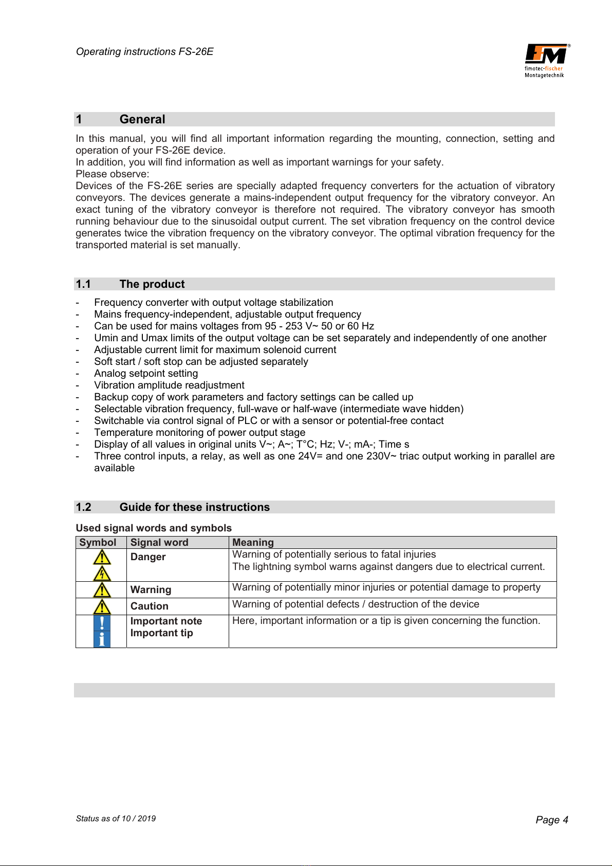
1.2 Guide for these instructions
Used signal words and symbols
Symbol Signal word Meaning
Danger Warning of potentially serious to fatal injuries
The lightning symbol warns against dangers due to electrical current.
Warning Warning of potentially minor injuries or potential damage to property
Caution Warning of potential defects / destruction of the device
Important note
Important tip
Here, important information or a tip is given concerning the function.

Operating instructions FS-26E
Status as of 10 / 2019 Page 5
1.3 Safety-related information for the user
These instructions contain the required information for the intended use of the device described
herein. They are directed toward technically qualified personnel.
Qualified personnel are people who have been authorized by persons responsible for the safety
of the system to execute the required activities and are able to recognize potential dangers and
avoid them based on their training, experience and instruction, as well as their knowledge of
relevant standards, regulations, accident prevention regulations and operating conditions
(definition of skilled personnel according to IEC 364).
Caution: Danger due to electric voltage.
Nonobservance can lead to death, serious bodily injury, or
cause property damage
The following safety information is for your protection, the protection of third parties as well as the
protection of the device. You should therefore observe it under all circumstances.
- Disconnect the power supply before installation or dismantling work, as well as when changing a fuse
or making changes to the setup.
- Observe the valid accident prevention and safety regulations for your specific application.
- Before commissioning, check whether the nominal voltage of the device agrees with the local mains
voltage.
- Emergency Stop mechanisms must remain active in all operating modes. Unlocking the Emergency
Stop mechanism must not result in uncontrolled reactivation.
- The electrical connections must be covered.
- Protective conductor connections must be checked for perfect function after installation.
Operating environment
The device must not come into direct contact with water.
When changing from cold to warm environments, allow the device to temper for a few hours before
putting it into operation; otherwise, damage could occur due to condensation water.
Do not install the control device near devices which generate strong electromagnetic fields. The function
could be disturbed as a result.
Also avoid environments which are very hot, cold or wet.
Power supply
Only connect the device to a grounded mains socket with a mains voltage of 95-253 V~/50 Hz or 95-
253V~/60 Hz.
If you notice malfunctions, disconnect the device from the mains. Have the device checked by qualified,
skilled personnel, and have it repaired if necessary.
The device
For safety and licensing reasons (CE), it is not permitted to convert and/or modify the device without
authorization.
The device meets the valid low-voltage and EMC directive.
Operating instructions FS-26E
Status as of 10 / 2019 Page 6
Operation
The control device only functions correctly when it is correctly installed and operated. In the event of
malfunctions or unclear operating states, you should check the device and remedy the malfunction
(see "Error list" chapter) or have it remedied.
- To avoid the risk of injury, do not allow uninstructed personnel or other vulnerable/endangered
persons to operate the device without supervision.
Warning:
For applications requiring constant switching ON and OFF of the
vibratory conveyor device (e.g., accumulation shutdown, hopper control, etc.),
the control input intended for this must be used.
If the load current circuit is interrupted via a switch or relay, the
control device could be damaged.
If the control device is switched on, the device plug on the operated
vibratory conveyor device may never be plugged in or unplugged. The control device
might be damaged as a result.
Parameters which are in the menu structure but are not described in these instructions represent
spaceholders which either have no function or are not yet meant for use in the current version.
Therefore, avoid activating these menu items or contact Support.
1.4 Intended use
The device described here is an electrical piece of equipment for use in industrial systems.
It is designed to control vibratory conveyors.
A use other than the one described above is improper and can result in injuries as well as property
damage.
(Further information about this topic can be found in the "Safety information" chapter).

Operating instructions FS-26E
Status as of 10 / 2019 Page 7
2 Application
The electronic frequency converter FS 26 is used for the infinitely variable control of inductive loads,
such as spiral conveyors, linear conveyors and hoppers.
The device works according to the principle of pulse width modulation within the half-waves with
adjustable periods of 5 - 200 Hz; the conveying capacity is adjusted by adjusting the magnet voltage via
the membrane keypad embedded in the housing cover or alternatively selectable via 0-10 V DC, 4-
20 mA or an external 10 kOhm potentiometer in the range of 1V~ up to the maximum output voltage. By
limiting the upper and lower setpoint limits, the optimal specified range can be moved along via the
setpoint.
The amplitude of the sinusoidal output current (upper half-wave) depends on the set period and is
therefore constant. The vibration frequency is set via the keypad as standard.
After switching on the mains voltage, the integrated, adjustable soft start is started and ensures the
output voltage starts up jerk-free up to the set voltage value. A limiter stage limits the load current of the
capacitors to 6 A in the moment of switch-on. Possible switch-on peaks are minimized this way.
Furthermore, both the soft start as well as the soft stop when the output voltage is switched on/off are
activated via the control input and are for increasing and decreasing the conveying capacity with time
control so that ordered bulk material does not change its position again. Both times can be adjusted
separately.
The control inputs allow the device to be switched on and off by another system (PLC, initiator, sensors,
etc.). The control device therefore provides its own supply voltage of +24 V DC. Switching on or off via an
external voltage of + 24 V DC is also possible.
Via the additionally integrated outputs, external devices can be operated or controlled, depending on the
logic specification.
The device provides an input for connecting an acceleration sensor for readjusting the output voltage.
Note
By determining the mains voltage and output current, changes are registered immediately and
compensated for by a controller stage, i.e. the output voltage remains stable. This way, the bulk
material is guaranteed to run smoothly.
Tip
On the control device, small magnets can also be safely operated.

Operating instructions FS-26E
Status as of 10 / 2019 Page 8
3 Installation
There are 2 bores and 2 elongated holes accessible from the outside for fastening the device. These are
separated from the device interior.
Important note
Fasten the device to a vibration-free surface.
Caution:
Please make sure that the ribbon cable and control cable are not pinched against the housing in
the interior. Pinching can cause short circuits and the destruction of the device.
Important note
Connection lines must be shielded!
Warning:
Procedure for high voltage test:
L and N must be connected with each other.
Test voltage may not be higher than 1000 V AC.
Every device must be tested separately.
If the above criteria are not complied with, the device could be damaged and the warranty will be
void.
Caution:
The cover of the device is made of plastic. Screwing on the cover with the six countersunk
screws must not be done with force, since otherwise there is a risk of the plastic cracking.
Screw in screws with a commercially available screwdriver by hand until the screw is flush with
the recess and the cover lies on the profile.

Operating instructions FS-26E
Status as of 10 / 2019 Page 9
3.1 Overview and dimensions
A - M12x1.5 Blind plug
B - Flange socket, 2-pin, for connecting enable input (E1) – X21
C - Socket M12x1, 4-pin, for connecting oscillation amplitude sensor and valve output 1 (A1) – X24
D - Flange plug, 3-pin, for connecting status output (A5) – X23
S - Flange socket, 4-pin, for connecting sensor inputs (E2 + E3) – X22
F - Mains supply line
G - Grounding bolt
H - Vibratory conveyor connection 3+PE
I - Mains voltage connection via STAKEI20 – X10
K - Connection, valve output 2 via STAKEI20 – X12
L - Mains switch
M - Mains fuse
Operating instructions FS-26E
Status as of 10 / 2019 Page 10
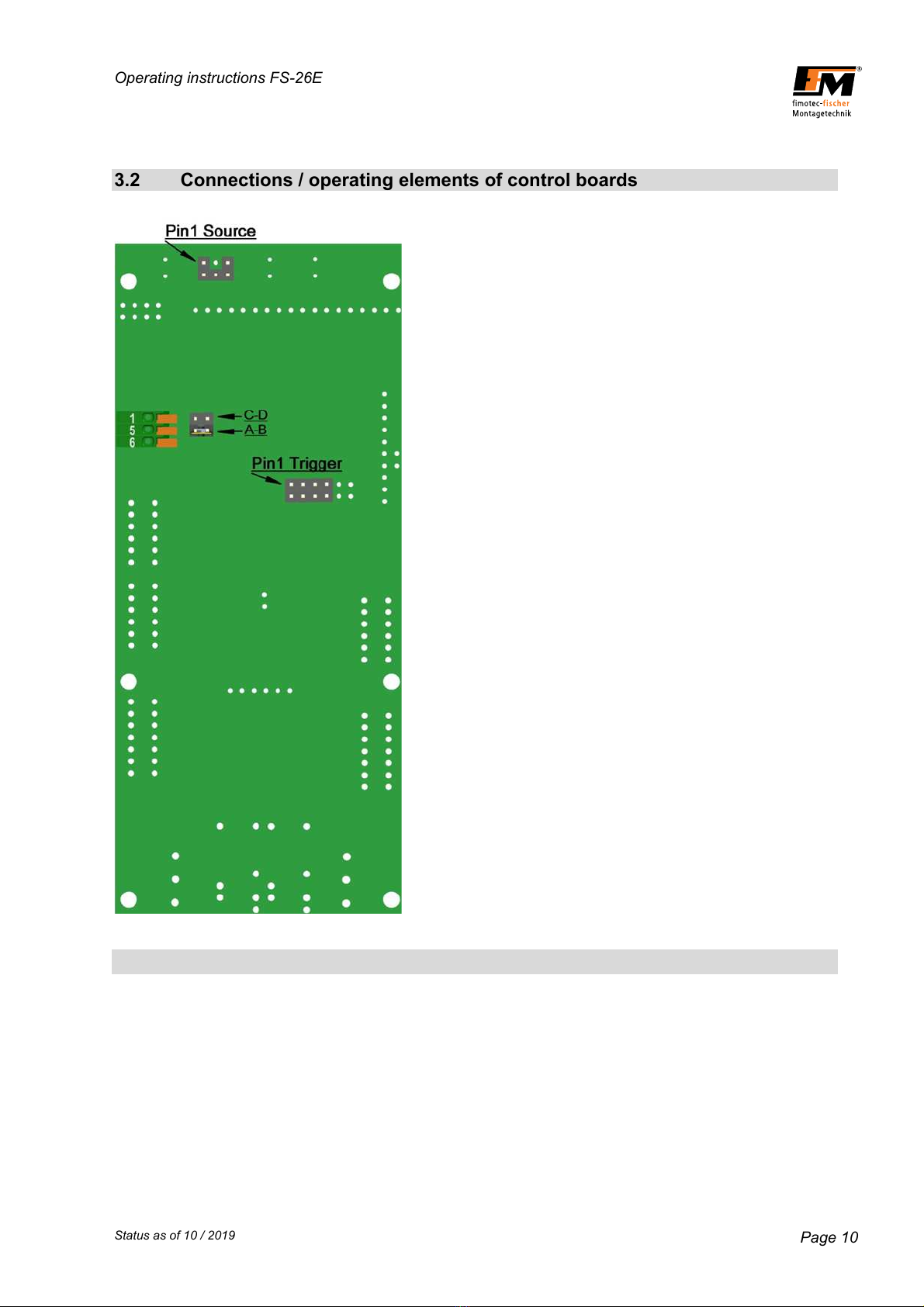
3.2 Connections / operating elements of control boards

Operating instructions FS-26E
Status as of 10 / 2019 Page 11
3.3 Housing connections
Vibratory conveyor connection
Pin 1 - Load
Pin 2 - Load
Pin 3 - Not Connected
PE - Protective conductor
Mains voltage connection
Pin 1 - L
Pin 2 - N
PE - Protective conductor
Connection, valve output 2
Pin 1 - L
Pin 2 - N
PE - Protective conductor
Attention: Output X12 is switched on and off
parallel to output X24.
Connection, higher-level enable input E1
Pin 1 - 24V=
Pin 2 - Enable input (menu: E1)
(can only be actuated potential-freely)
Connection, status output A5
Pin 1 - N.O.
Pin 2 - Root
Pin 3 - N.C.
Sensor input connection E2+E3
Pin 1 - +24 V=
Pin 2 - GND
Pin 3 - Sensor input 2 (menu: E3)
Pin 4 - Sensor input 1 (menu: E2)
Connection, oscillation sensor + valve output 1 (A1)
Pin 1 - +24 V=
Pin 2 - Valve output (menu: A1)
Pin 3 - GND
Pin 4 - Vibration amplitude input
The +24 V DC supply is isolated from the mains voltage.
X12
X10
X11
X24

Operating instructions FS-26E
Status as of 10 / 2019 Page 12
4 Commissioning
Before connecting the device, the mains voltage and frequency must be determined. The data
must lie in the range of permissible values for the device.
- Check and set the jumpers according to the control type.
- Connect the vibratory conveyor and control cable to the control device.
- Stick the mains plug of the control device in the socket.
- Switch on the control device.
- Via the keypad, define the Umin and Umax limits of the required output voltage range.
- Via the keypad for the soft start and soft stop, define the characteristics for switching the control input
on and off.
Operating note
Before switching on, check to make sure the plug connections are correct.
Switch on the control device with the mains switch.
Set the setpoint via the keypad in the cover until the vibratory conveyor
reaches the desired conveying capacity.
Warning:
All parts of the vibration drive must be grounded (magnet and armature).
Vibration drives with plastic springs are to be checked then.

Operating instructions FS-26E
Status as of 10 / 2019 Page 13
4.1 Control panel
The device is operated/set via 8 keys which are located on a
control panel on the cover, together with a 6 x7-segment LED
display.
All operating mode settings as well as the settable parameters can
be made via this control panel.
Operating note: Power output ON/OFF
By simultaneously pressing the 6 and 7 keys,
the device can be switched on/off; thereby,
however, there is no disconnection from the mains;
only the power semiconductors are shut off.
Display
or
Operating note: Jump to amplitude display
By simultaneously pressing the 2 and 3 keys, the
"Amplitude" root display is called up.
Display
VALUE KEYS 0 and 1
MENU KEYS 2 and 3
PROGRAMMING KEY 4
SAVE KEY 5
LEVEL KEYS 6 and 7
Operating note: Error status query
If an error is registered, the display starts to flash. By pressing the 0 or 1 key, the
error will be shown.
Display (example)
Operating note: Show software version and revision
By simultaneously pressing the 4 and 5 keys and keeping them pressed, the
software number and revision date will be displayed in succession.
Display (example)
-> ->

Operating instructions FS-26E
Status as of 10 / 2019 Page 14
Keypad explanation
The parameters are set by means of a menu structure and by entering an operator code.
In the "Setting instructions", the menu structure and the setting ranges of the parameters, as well as the
function programming, will be explained.
By briefly pressing the arrow key 0 (increase/change) or 1 (decrease/change), the value in the selected
parameter is increased/reduced or changed by one position (ones, tenths or mode). If the one or other
key is kept pressed, it switches to fast mode, and after approx. 1 s to 2x fast mode.
If arrow keys 2 (clockwise rotation) and 3 (counterclockwise rotation) are briefly pressed, it switches
from one parameter to the next. If the one or other key is kept pressed, the parameters are rolled
through.
By briefly pressing the arrow keys 6 (increase) and 7 (decrease), the level structure is changed from one
level to the other. If the one or other key is kept pressed, the levels are rolled through.
When the 4 key is pressed in the "Amplitude" root display, programming mode is switched to without
entering an operator code. The amplitude can now be changed with the 0 and 1 keys.
If the 4 key is pressed in all other parameters, the entry of an operator code is expected.
-> .
After entering the code, this must be confirmed with the 5 key. If the code is correct, programming mode
is switched to. Depending on the access authorization (different codes are available for this; see the
"Operator codes" chapter), parameter items can be changed accordingly.
After completing the changes, these must be stored with the 5 key.
appears briefly.
Changes are discarded one minute (timeout) after the last key was pressed and without
pressing the '5' key; the values before changing into programming mode are restored.
Exiting programming mode through "timeout" is indicated by the flashing of the
programming dot in the second LED from the left. The dot flashes 3x
before programming mode is exited.
Programming mode can be exited sooner by pressing the 4 key again without saving.
Programming mode is indicated by the dot in the second LED from the left.
Security query
For some parameters, before executing the function "Read" or
"Save", there is a security query
To confirm, the 5 key must be pressed again. To exit without executing
the function, the keys 0 - 1 - 2 - 3 - 4 - 6 - 7 can be pressed.
Operating instructions FS-26E
Status as of 10 / 2019 Page 15
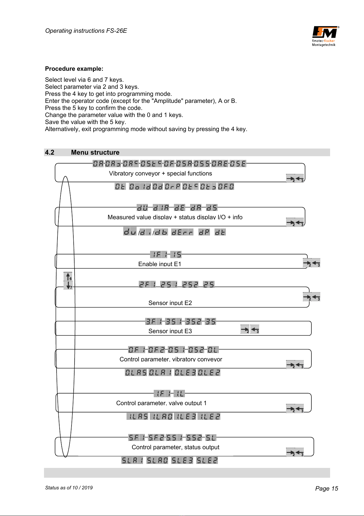
Vibratory conveyor + special functions
Procedure example:
Select level via 6 and 7 keys.
Select parameter via 2 and 3 keys.
Press the 4 key to get into programming mode.
Enter the operator code (except for the "Amplitude" parameter), A or B.
Press the 5 key to confirm the code.
Change the parameter value with the 0 and 1 keys.
Save the value with the 5 key.
Alternatively, exit programming mode without saving by pressing the 4 key.
4.2 Menu structure
/ /
Enable input E1
Sensor input E2
Sensor input E3
Control parameter, vibratory conveyor
Control parameter, valve output 1
Control parameter, status output
Measured value display
+
status display I/O
+
info

Operating instructions FS-26E
Status as of 10 / 2019 Page 16
4.3 LEVEL 0 - Performance parameter, vibratory conveyor drive
After power ON, the display switches to the "Amplitude" root display. Depending on this, the 2 and 3 keys
can be used to roll to every individual parameter on this level. The following parameters are available:
Parameter: Amplitude [V~]
Without code Value can be set from 1 - 230 max.
Increment1V~
Max. voltage depends on mains voltage range.
Parameter: min. amplitude limit [V~]
Code B Value can be set from 1 - 230, depending on the mains voltage range
Increment1V~
Limited by max. amplitude limit
Parameter: max. amplitude limit [V~]
Code B Value can be set from 1 - 230, depending on the mains voltage range
Increment1V~
Limited by min. amplitude limit
Parameter: Current limitation [A~] for the vibratory conveyor
Code B Value can be set from 0.1 - 6.0
Increment0.1A~
For protection of the magnets the value is set to the max. permissible current
of all connected magnets.
Parameter: Frequency [Hz]
Code B Value can be set from 5.0 - 99.9 / 100 - 200
Increment 0.1 Hz, then starting from 100 Hz, increment is 1 Hz
The specified frequency is equivalent to the mains frequency, i.e. set 50 Hz
corresponds to the mains frequency of 50 Hz -> 6.000 oscillations per minute.
Vibrations per minute = frequency x 60 x 2
Parameter: Soft start [s]
Code A and B Value can be set from 0.1 - 5.0
Increment0.1s
Voltage ramp from 0V~ to the set amplitude value
within the set time.

Operating instructions FS-26E
Status as of 10 / 2019 Page 17
Parameter: Soft stop [s]
Code A and B Value can be set from 0.1 - 5.0
Increment0.1s
Voltage ramp from the set amplitude value to 0V~ within the
set time.
Parameter: Setpoint specification [function]
Code A and B Value can be set to F, I, P, U, b
F - Setpoint specified via membrane keypad
I - Setpoint specified via analog current 4 - 20 mA=
U - Setpoint specified via analog voltage 0 - 10 V=
P - Setpoint specified via potentiometer 10K
b - Setpoint specified via acceleration sensor
Parameter acceleration sensor selection
Code B Value can be set to 0, U, I,
Visible after code input 0 - No acceleration sensor connected
U-Acceleration sensor with voltage output
I - Acceleration sensor with current output
If a sensor type is activated, the menu for the setpoint specification is supplemented with menu item b.
Setpoint specification for acceleration sensor.
Parameter wave form selection [function]
Code B Value can be set to G, H
G - Full-wave ^^^^^^
H - Half-wave ^ ^ ^ (only every other oscillation is output)
Parameter min. acceleration limit [g]
Code B Value can be set to 0.0 - 20.0
Visible after code input increment 0.1 g
Lower value in readjustment range
Parameter max. acceleration limit [g]
Code B Value can be set to 0.0 - 20.0
Visible after code input increment 0.1 g
Upper value in readjustment range
Control parameter proportional component (closed-loop gain)
Code B Value can be set to 0.1 - 19.9
Visible after code input increment 0.1 g
Default5.0
Operating instructions FS-26E
Status as of 10 / 2019 Page 18
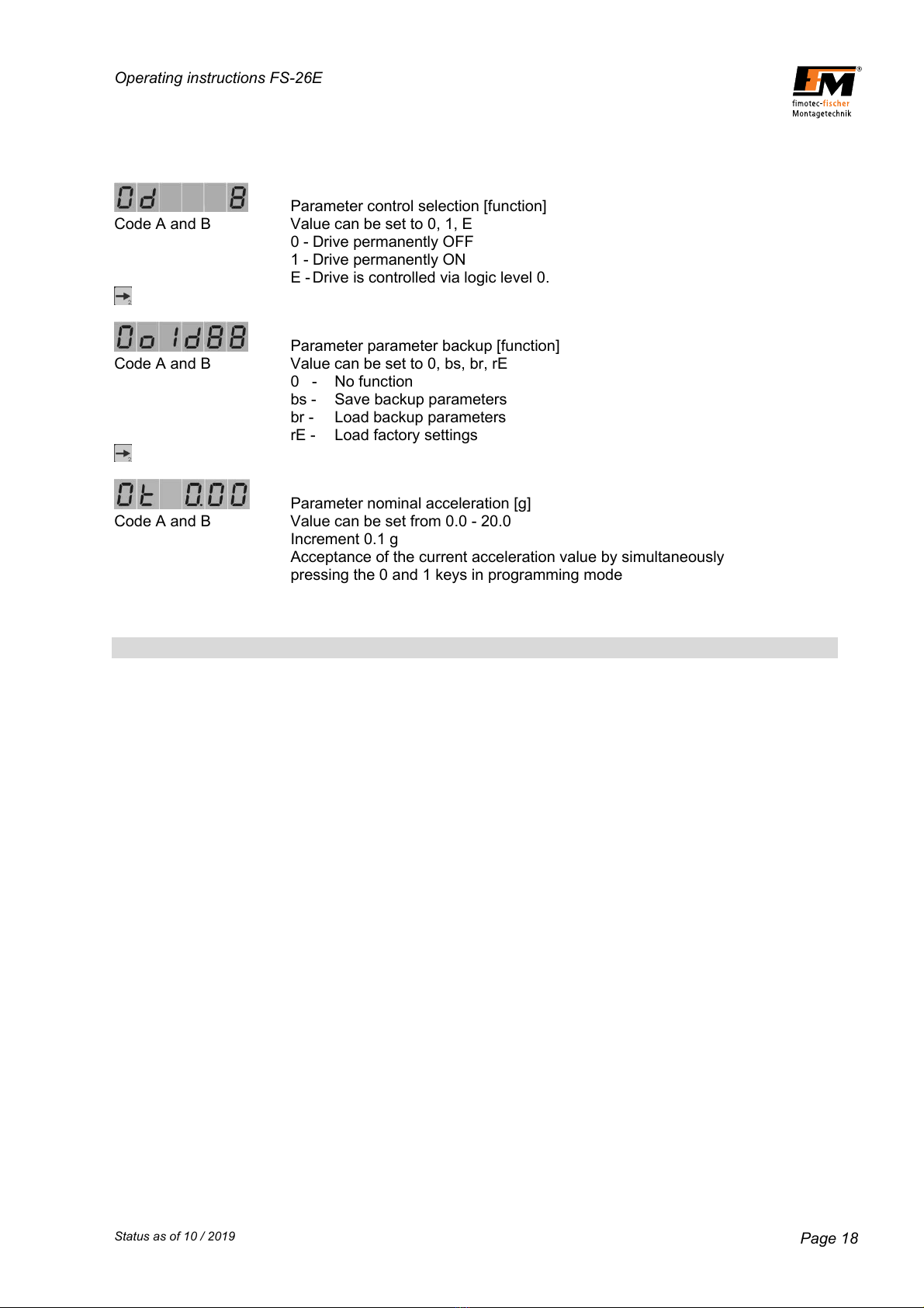
Parameter control selection [function]
Code A and B Value can be set to 0, 1, E
0 - Drive permanently OFF
1 - Drive permanently ON
E - Drive is controlled via logic level 0.
Parameter parameter backup [function]
Code A and B Value can be set to 0, bs, br, rE
0 - No function
bs - Save backup parameters
br - Load backup parameters
rE - Load factory settings
Parameter nominal acceleration [g]
Code A and B Value can be set from 0.0 - 20.0
Increment 0.1 g
Acceptance of the current acceleration value by simultaneously
pressing the 0 and 1 keys in programming mode

Operating instructions FS-26E
Status as of 10 / 2019 Page 19
4.4 LEVEL d - Information output (display only)
After power ON, the display switches to the "Amplitude" root display. From here, the 6 key can be used
to change to level d. The following values and status displays are available:
Value: Mains voltage [V~]
The currently applied mains voltage is displayed.
Value: Output current [A~]
The currently flowing magnet current is displayed.
Status display: Inputs E1 - E6, depending on availability.
The upper row of line segments shows the physical status, i.e. a line segment
is displayed when voltage is applied to the corresponding input.
E.g.: 24 V DC at E2 = line segment, upper row, pos. 2 from the left
The lower row of line segments shows the logical status, i.e. the status after
processing inversion and times.
E.g.: 0 V at E1 + F1=S = line segment, bottom row, pos. 1 from the left
Status display: Outputs A0 - A7, depending on availability.
The upper row of line segments shows the physical status, i.e. if voltage
is applied to the corresponding output, a line segment is displayed.
E.g.: 24 V DC at A1 = line segment, upper row, pos. 2 from the left
The lower row of line segments shows the logical status, i.e. according to the
logical input and output links and after processing of
inversionandtimes.
E.g.: 24 V DC at A2 + F2=S = line segment, bottom row, pos. 3 from the left
Status display: Inputs and outputs, depending on availability.
The upper row of line segments shows the physical status of the inputs,
i.e. if voltage is applied at the corresponding input, a line segment is displayed.
The lower row of line segments shows the physical status of the outputs,
i.e. if there is voltage applied at the corresponding output, a line segment is
displayed.
Value: Temperature [°C]
The temperature on the power output stage is output.
Values up to 110 are permissible.
Operating instructions FS-26E
Status as of 10 / 2019 Page 20
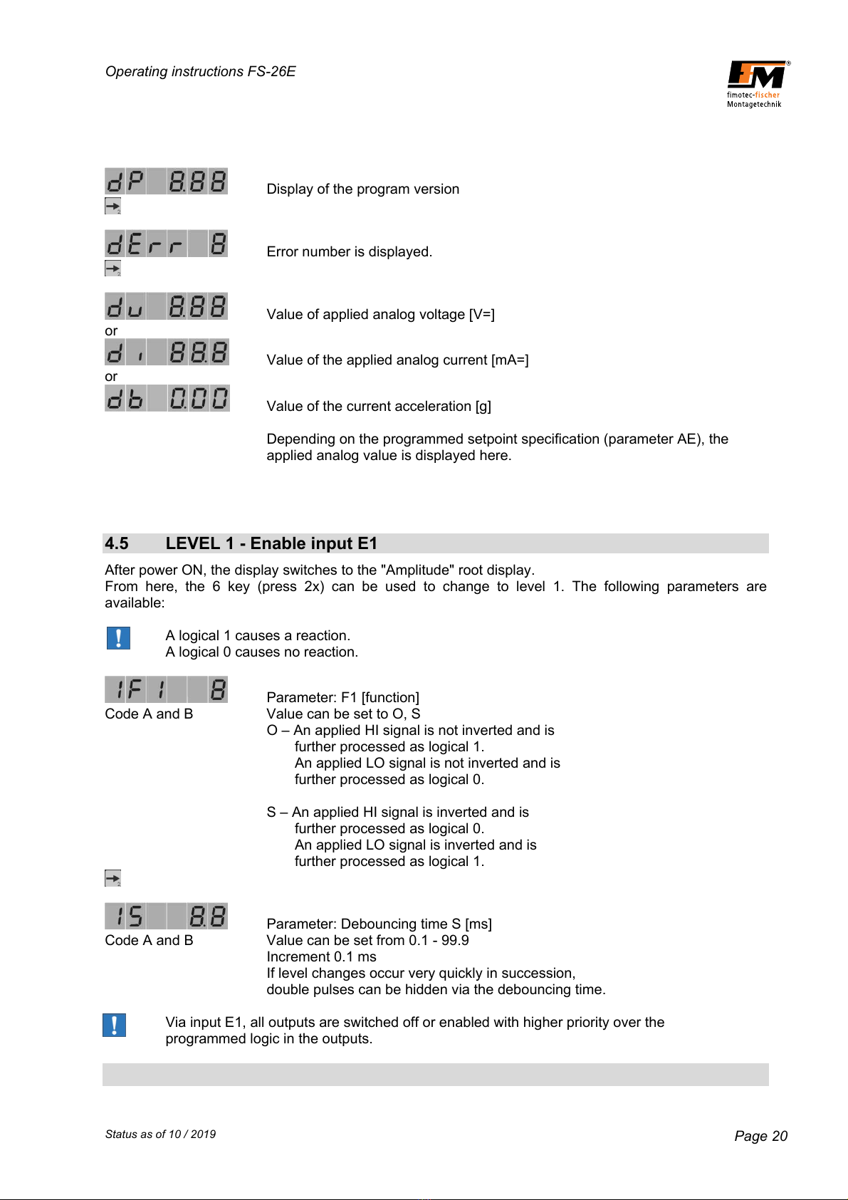
Display of the program version
Error number is displayed.
Value of applied analog voltage [V=]
or
Value of the applied analog current [mA=]
or
Value of the current acceleration [g]
Depending on the programmed setpoint specification (parameter AE), the
applied analog value is displayed here.
4.5 LEVEL 1 - Enable input E1
After power ON, the display switches to the "Amplitude" root display.
From here, the 6 key (press 2x) can be used to change to level 1. The following parameters are
available:
A logical 1 causes a reaction.
A logical 0 causes no reaction.
Parameter: F1 [function]
Code A and B Value can be set to O, S
O – An applied HI signal is not inverted and is
further processed as logical 1.
An applied LO signal is not inverted and is
further processed as logical 0.
S – An applied HI signal is inverted and is
further processed as logical 0.
An applied LO signal is inverted and is
further processed as logical 1.
Parameter: Debouncing time S [ms]
Code A and B Value can be set from 0.1 - 99.9
Increment0.1ms
If level changes occur very quickly in succession,
double pulses can be hidden via the debouncing time.
Via input E1, all outputs are switched off or enabled with higher priority over the
programmed logic in the outputs.
Operating instructions FS-26E
Status as of 10 / 2019 Page 21
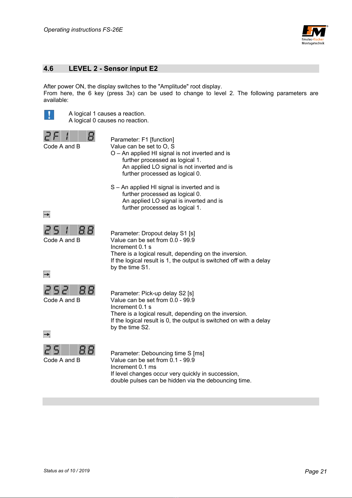
4.6 LEVEL 2 - Sensor input E2
After power ON, the display switches to the "Amplitude" root display.
From here, the 6 key (press 3x) can be used to change to level 2. The following parameters are
available:
A logical 1 causes a reaction.
A logical 0 causes no reaction.
Parameter: F1 [function]
Code A and B Value can be set to O, S
O – An applied HI signal is not inverted and is
further processed as logical 1.
An applied LO signal is not inverted and is
further processed as logical 0.
S – An applied HI signal is inverted and is
further processed as logical 0.
An applied LO signal is inverted and is
further processed as logical 1.
Parameter: Dropout delay S1 [s]
Code A and B Value can be set from 0.0 - 99.9
Increment0.1s
There is a logical result, depending on the inversion.
If the logical result is 1, the output is switched off with a delay
by the time S1.
Parameter: Pick-up delay S2 [s]
Code A and B Value can be set from 0.0 - 99.9
Increment0.1s
There is a logical result, depending on the inversion.
If the logical result is 0, the output is switched on with a delay
by the time S2.
Parameter: Debouncing time S [ms]
Code A and B Value can be set from 0.1 - 99.9
Increment0.1ms
If level changes occur very quickly in succession,
double pulses can be hidden via the debouncing time.

Operating instructions FS-26E
Status as of 10 / 2019 Page 22
4.7 LEVEL 3 - Sensor input E3
After power ON, the display switches to the "Amplitude" root display.
From here, the 6 key (press 4x) can be used to change to level 3. The following parameters are
available:
A logical 1 causes a reaction.
A logical 0 causes no reaction.
Parameter: F1 [function]
Code A and B Value can be set to O, S
O – An applied HI signal is not inverted and is
further processed as logical 1.
An applied LO signal is not inverted and is
further processed as logical 0.
S – An applied HI signal is inverted and is
further processed as logical 0.
An applied LO signal is inverted and is
further processed as logical 1.
Parameter: Dropout delay S1 [s]
Code A and B Value can be set from 0.0 - 99.9
Increment0.1s
There is a logical result, depending on the inversion.
If the logical result is 1, the output is switched off with a delay
bythetimeS1
Parameter: Pick-up delay S2 [s]
Code A and B Value can be set from 0.0 - 99.9
Increment0.1s
There is a logical result, depending on the inversion.
If the logical result is 0, the output is switched on with a delay
bythetimeS2
Parameter: Debouncing time S [ms]
Code A and B Value can be set from 0.1 - 99.9
Increment0.1ms
If level changes occur very quickly in succession,
double pulses can be hidden via the debouncing time.
This manual suits for next models
1
Table of contents
Popular Control Unit manuals by other brands

Tork
Tork EW101B Programming instructions

LOVATO ELECTRIC
LOVATO ELECTRIC EXP10 15 instruction manual

Datalogic
Datalogic SG EASY One instruction manual

Quintex
Quintex Cheetah C3 CUB operating & maintenance manual

Baumuller
Baumuller B MaXX 4000 Series Instruction handbook

Baumuller
Baumuller b maXX BM4-O-CAN-03 Instruction handbook


NI
NI PXIe-5673E Getting started guide

CHENGDU VANTRON TECHNOLOGY
CHENGDU VANTRON TECHNOLOGY AP6255 user manual

Viessmann
Viessmann EM-EA1 extension Installation and service instructions

TLV
TLV RT3A instruction manual

Fermax
Fermax LYNX SKYLINE Quick start manual

SIMCom Wireless Solutions
SIMCom Wireless Solutions SIM7600A-H user manual