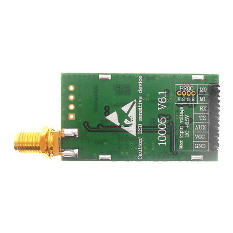
SIMCom Wireless Solutions SIM7600A-H User manual

SIM7600A-H_User Manual_V1.00

SmartMachineSmartDecision
SIM7600A-H_User Manual_V1.00 2017-11-24
2
Compliance Information:
FCC Compliance Statement: This device complies with Part 15 of the FCC Rules . Operation is
subject to the following two conditions: 1. This device may not cause harmful interference, and 2.
This device must accept any interference received, including interference that may cause undesired
operation. This device must accept any interference received, including interference that may cause
undesired operation. Product that is a radio transmitter is labeled with FCC ID.
FCC Caution:
(1)Exposure to Radio Frequency Radiation. This equipment must be installed and operated in
accordance with provided instructions and the antenna(s) used for this transmitter must be installed
to provide a separation distance of at least 20 cm from all persons and must not be collocated or
operating in conjunction with any other antenna or transmitter. End-users and installers must be
provided with antenna installation instructions and transmitter operating conditions for satisfying RF
exposure compliance.
(2)Any changes or modifications not expressly approved by the grantee of this device could void the
user's authority to operate the equipment.
(3)This Transmitter must not be co-located or operating in conjunction with any other antenna or
transmitter.
(4)Changes or modifications to this unit not expressly approved by the party responsible for
compliance could void the user authority to operate the equipment.
(5) the modules FCC ID is not visible when installed in the host, or (6) if the host is marketed so that
end users do not have straight forward commonly used methods for access to remove the module so
that the FCC ID of the module is visible; then an additional permanent label referring to the enclosed
module: Contains Transmitter Module FCC ID: UDV-201710 or Contains FCC ID: UDV-201710

SmartMachineSmartDecision
SIM7600A-H_User Manual_V1.00 2017-11-24
3
Document Title SIM7600A-H_User Manual
Version V1.00
Date 2017-11-24
Status Released
Document Control ID SIM7600A-H_User Manual_V1.00
General Notes
SIMCom offers this information as a service to its customers to support the application and
engineering efforts that use the products designed by SIMCom. The information provided is based
on the requirements specifically from the customers. SIMCom has not undertaken any independent
search for additional relevant information, including any information that may be in the customer’s
possession. Furthermore, the system validation of the product designed by SIMCom within a larger
electronic system remains the responsibility of the customer or the customer’s system integrator.
All specifications supplied herein are subject to change without notice.
Copyright
This document contains the proprietary technical information which is the property of SIMCom
Limited, copying of this document, giving it to others, the using or communication of the contents
thereof are forbidden without the official authority by SIMCom. Offenders are liable to the
payment of the damages. All rights are reserved in the event of grant of a patent or the registration
of a utility model or design. All specifications supplied herein are subject to change without notice
Copyright © SIMCom Wireless Solutions Co., Ltd. 2017

SmartMachineSmartDecision
SIM7600A-H_User Manual_V1.00 2017-11-24
4
Contents
Contents .............................................................................................................................................4
Table Index ........................................................................................................................................6
Figure Index ......................................................................................................................................7
Revision History................................................................................................................................8
1Introduction................................................................................................................................9
1.1Product Outline .....................................................................................................................9
1.2Hardware Interface Overview ...............................................................................................9
1.3Hardware Block Diagram......................................................................................................9
1.4Functional Overview...........................................................................................................10
2Package Information ...............................................................................................................12
2.1Pin Assignment Overview...................................................................................................12
2.2Pin Description....................................................................................................................14
2.3Mechanical Information ......................................................................................................18
2.4Footprint Recommendation.................................................................................................19
3Interface Application ...............................................................................................................20
3.1Power Supply ......................................................................................................................20
3.1.1Power supply Design Guide .........................................................................................20
3.1.2Recommended Power Supply Circuit ..........................................................................21
3.1.3Voltage Monitor............................................................................................................22
3.2Power on/Power off/Reset Function....................................................................................22
3.2.1Power on.......................................................................................................................22
3.2.2Power off ......................................................................................................................23
3.2.3Reset Function..............................................................................................................24
3.3UART Interface...................................................................................................................25
3.3.1UART Design Guide ....................................................................................................25
3.3.2RI and DTR Behavior...................................................................................................27
3.4USB Interface......................................................................................................................27
3.4.1USB Application Guide................................................................................................28
3.5USIM Interface....................................................................................................................28
3.5.1USIM Application Guide..............................................................................................29
3.5.2SIM Card Design Guide...............................................................................................29
3.5.3Recommended USIM Card Holder ..............................................................................30
3.6PCM Interface .....................................................................................................................31
3.6.1PCM Timing.................................................................................................................31
3.6.2PCM Application Guide ...............................................................................................32
3.7I2C Interface .......................................................................................................................33
3.7.1I2C Design Guide.........................................................................................................33
3.8Network Status....................................................................................................................34
3.9Operating Status Indication.................................................................................................34
3.10Pin Multiplex Function ....................................................................................................34

SmartMachineSmartDecision
SIM7600A-H_User Manual_V1.00 2017-11-24
5
3.11Other interface .................................................................................................................35
3.11.1Sink Current Source..................................................................................................35
3.11.2ADC ..........................................................................................................................36
4RF Specifications......................................................................................................................37
4.1WCDMA/LTE RF Specifications .......................................................................................37
4.2WCDMA/LTE Antenna Design Guide................................................................................38
4.3GNSS ..................................................................................................................................41
4.3.1GNSS Technical specification......................................................................................41
4.3.2GNSS Application Guide .............................................................................................42
5Electrical Specifications...........................................................................................................44
5.1Absolute Maximum Ratings................................................................................................44
5.2Operating Conditions ..........................................................................................................44
5.3Operating Mode ..................................................................................................................45
5.3.1Operating Mode Definition ..........................................................................................45
5.3.2Sleep Mode...................................................................................................................46
5.3.3Minimum Functionality Mode and Flight Mode..........................................................46
5.4Current Consumption ..........................................................................................................46
5.5ESD Notes...........................................................................................................................47
6SMT Production Guide ...........................................................................................................48
6.1Top and Bottom View of Module........................................................................................48
6.2Typical SMT Reflow Profile ...............................................................................................48
6.3Moisture Sensitivity Level (MSL) ......................................................................................49
6.4Stencil Foil Design Recommendation.................................................................................49
7Packaging..................................................................................................................................50
Appendix..........................................................................................................................................52
A. Reference Design......................................................................................................................52
B. Coding Schemes and Maximum Net Data Rates over Air Interface.........................................53
C. Related Documents...................................................................................................................55
D. Terms and Abbreviations..........................................................................................................57
E. Safety Caution...........................................................................................................................59

SmartMachineSmartDecision
SIM7600A-H_User Manual_V1.00 2017-11-24
6
Table Index
Table 1: SIM7600A-H frequency bands ..............................................................................................................9
Table 2: General features ...................................................................................................................................10
Table 3: Pin Definitions .....................................................................................................................................13
Table 4: IO parameters definition.......................................................................................................................14
Table 5: Pin description......................................................................................................................................14
Table 6: VBAT Pins electronic characteristic..................................................................................................... 20
Table 7: Recommended zener diode list.............................................................................................................21
Table 8: Power on timing and electronic characteristic......................................................................................23
Table 9: Power off timing and Electronic Characteristic....................................................................................24
Table 10: RESET pin electronic characteristic...................................................................................................25
Table 11: USIM Electronic characteristic in 1.8V mode (USIM_VDD=1.8V).................................................. 28
Table 12: USIM Electronic characteristic 3.0V mode (USIM_VDD=2.95V)....................................................29
Table 13: Amphenol USIM Socket Pin Description...........................................................................................30
Table 14: PCM Format....................................................................................................................................... 31
Table 15: PCM Timing Parameters ....................................................................................................................32
Table 16: NETLIGHT pin status........................................................................................................................34
Table 17: Pin definition of the STATUS ............................................................................................................34
Table 18: Pin multiplex function list.................................................................................................................. 35
Table 19: Sink current electronic characteristic .................................................................................................35
Table 20: ADC Electronic Characteristics.......................................................................................................... 36
Table 21: Conducted transmission power .......................................................................................................... 37
Table 22: Operating frequencies ........................................................................................................................37
Table 23: Conducted receive sensitivity.............................................................................................................37
Table 24: Reference sensitivity (QPSK) ............................................................................................................37
Table 25: Trace Loss ..........................................................................................................................................38
Table 26: Recommended TVS ...........................................................................................................................39
Table 27: LNA requirements..............................................................................................................................43
Table 28: Absolute maximum ratings.................................................................................................................44
Table 29: Recommended operating ratings ........................................................................................................44
Table 30: 1.8V Digital I/O characteristics*........................................................................................................44
Table 31: Operating temperature........................................................................................................................45
Table 32: Operating mode Definitions ...............................................................................................................45
Table 33: Current consumption on VBAT Pins (VBAT=3.8V) ..........................................................................47
Table 34: The ESD performance measurement table (Temperature: 25℃, Humidity: 45%) .............................47
Table 35: Moisture Sensitivity Level and Floor Life .........................................................................................49
Table 36: Tray size............................................................................................................................................. 50
Table 37: Small Carton size ...............................................................................................................................51
Table 38: Big carton size....................................................................................................................................51
Table 39: Coding schemes and maximum net data rates over air interface ........................................................53
Table 40: Related documents .............................................................................................................................55
Table 41: Terms and Abbreviations....................................................................................................................57
Table 42: Safety caution..................................................................................................................................... 59

SmartMachineSmartDecision
SIM7600A-H_User Manual_V1.00 2017-11-24
7
Figure Index
Figure 1: SIM7600A-H Block Diagram.............................................................................................................10
Figure 2: Pin assignment overview ....................................................................................................................12
Figure 3: Dimensions (Unit: mm) ......................................................................................................................18
Figure 4: Footprint recommendation (Unit: mm)............................................................................................... 19
Figure 5: Power supply application circuit.........................................................................................................20
Figure 6: Linear regulator reference circuit .......................................................................................................21
Figure 7: Switching modepower supply reference circuit.................................................................................. 21
Figure 8: ReferencePower on/offCircuit ............................................................................................................22
Figure 9: Power on timing sequence..................................................................................................................23
Figure 10: Power off timing sequence ...............................................................................................................24
Figure 11: Reference reset circuit ......................................................................................................................25
Figure 12: UART full modem ............................................................................................................................26
Figure 13: UART null Modem...........................................................................................................................26
Figure 14: Reference circuit of level shift.......................................................................................................... 26
Figure 15: RI behaviour(SMS and URC report)...........................................................................................27
Figure 16: RI behaviour(voice call)..............................................................................................................27
Figure 17: USB reference circuit .......................................................................................................................28
Figure 18: USIM interface reference circuit ......................................................................................................29
Figure 19: Amphenol SIM card socket ..............................................................................................................30
Figure 20: PCM_SYNC timing..........................................................................................................................31
Figure 21: EXT codec to module timing............................................................................................................31
Figure 22: Module to EXT codec timing ...........................................................................................................32
Figure 23: Audio codec reference circuit ...........................................................................................................33
Figure 24: I2C reference circuit .........................................................................................................................33
Figure 25: NETLIGHT reference circuit............................................................................................................34
Figure 26: ISINK reference circuit ....................................................................................................................35
Figure 27: Antenna matching circuit (MAIN_ANT)..........................................................................................38
Figure 28: Antenna matching circuit (DIV_ANT) .............................................................................................39
Figure 29: Antenna matching circuit (MAIN_ANT)..........................................................................................41
Figure 30: Active antenna circuit .......................................................................................................................42
Figure 31: Passive antenna circuit (Default) ......................................................................................................42
Figure 32: Top and bottom view of Module....................................................................................................... 48
Figure 33: The ramp-soak-spike Reflow Profile of Module...............................................................................48
Figure 34: Packaging introduce .........................................................................................................................50
Figure 34: Module tray drawing introduce.........................................................................................................50
Figure 36: Small carton drawing introduce........................................................................................................51
Figure 37: Big carton drawing introduce ...........................................................................................................51
Figure 38: Reference design ..............................................................................................................................52

SmartMachineSmartDecision
SIM7600A-H_User Manual_V1.00 2017-11-24
8
Revision History
Data Version Description of change Author
2017-11-24 V1.00 new Shengwu.sun

SmartMachineSmartDecision
SIM7600A-H_User Manual_V1.00 2017-11-24
9
1Introduction
This document describes the electronic specifications, RF specifications, interfaces, mechanical
characteristics and testing results of the SIMCom SIM7600A-H. With the help of this document
and other software application notes/user guides, users can understand and use modules to design
and develop applications quickly.
1.1 Product Outline
The SIM7600A-H support many air-interface standards, refer to the following table.
Table 1: SIM7600A-H frequency bands
Standard Frequency SIM7600A-H
WCDMA BAND2
BAND5
LTE
LTE-FDD B2
LTE-FDD B4
LTE-FDD B12
With a smallphysical dimension of 30*30*2.9 mm and with the functionsintegrated, the Module
can meet almost any space requirement in users’ applications, such as smart phones, PDA’s,
industrial handhelds, machine-to-machine, vehicle applications, etc.
1.2 Hardware Interface Overview
The interfaces that are described in detail in the next chapters include:
● Power Supply
● USB Interface
● UART Interface
● USIM Interface
● GPIO
● ADC
● Power Output
● Current Sink Source
● PCM Interface
● I2C Interface
1.3 Hardware Block Diagram
The block diagram of the Module is shown in the figure below.

SmartMachineSmartDecision
SIM7600A-H_User Manual_V1.00 2017-11-24
10
GSM/WCDMA
/LTE
RF FEM
GSM/
WCDMA/LTE PA
RF
Transceiver
Baseband
XO
19.2MHz
NAND
Flash
I2C
PCM
Interrupt
Status LED
USB
USIM
Power On
Reset
UART
GPIOs
ADC
LDO
VBAT
Sink Current Source
DDR
Main Antenna
Power
Management
Qualcomm
Chip
SMT Interface
WCDMA
/LTE
RF FEM
AUX Antenna
SYSTEM POWER
VBAT
GNSS RF
GNSS Antenna
Figure 1: SIM7600A-H Block Diagram
1.4 Functional Overview
Table 2: General features
Feature Implementation
Power supply Single supply voltage 3.4~4.2V
Power saving Current in sleep mode : <5mA
Radio frequency bands Please refer to the table 1
Transmitting power WCDMA: Class 3 (0.25W)
LTE: Class 3 (0.25W)
Data Transmission
Throughout
HSPA+: 5.76 Mbps(UL), 42 Mbps(DL)
LTE Category 4: 150 Mbps (DL)
LTE Category 4: 50 Mbps (UL)
Antenna WCDMA /LTE main antenna
WCDMA /LTE auxiliary antenna
SMS
MT, MO, CB, Text and PDU mode
SMS storage: USIM card or ME(default)
Transmission of SMS alternatively over CS or PS.
USIM interface Support identity card: 1.8V/ 3V
USIM application toolkit Support SAT class 3, GSM 11.14 Release 98
Support USAT
Phonebook management Support phonebook types: DC,MC,RC,SM,ME,FD,ON,LD,EN

SmartMachineSmartDecision
SIM7600A-H_User Manual_V1.00 2017-11-24
11
Audio feature
Support PCM interface
Only support PCM master mode and short frame sync, 16-bit linear data
formats
UART interface
A full modem serial port by default
Baud rate: 300bps to 4Mbps(default:115200bps)
Auto-bauding baud rate: 9600,19200,38400,57600,115200bps
Can be used as the AT commands or data stream channel.
Support RTS/CTS hardware handshake
Multiplex ability according to GSM 07.10 Multiplexer Protocol.
USB USB 2.0 specification-compliant as a peripheral
Firmware upgrade USB Firmware upgrade over USB interface
USB 2.0 specification-compliant as a peripheral
Physical characteristics Weight:5.5g
Size:30*30*2.9mm
Temperature range
Normal operation temperature: -30°C to +80°C
Extended operation temperature: -40°C to +85°C*
Storage temperature -45°C to +90°C
*Note: Module is able to make and receive voice calls, data calls, SMS and make
WCDMA/HSPA+/LTE traffic in -40℃~ +85℃. The performance will be reduced slightly from
the 3GPP specifications if the temperature is outside the normal operating temperature range
and still within the extreme operating temperature range.

SmartMachineSmartDecision
SIM7600A-H_User Manual_V1.00 2017-11-24
12
2Package Information
2.1 Pin Assignment Overview
All functions of the SIM7600A-H will be provided through 87 pads that will be connected to the
customers’ platform. The following Figure is a high-level view of the pin assignment of the
SIM7600A-H.
Figure 2: Pin assignment overview
SIM7600A
(Top View)

SmartMachineSmartDecision
SIM7600A-H_User Manual_V1.00 2017-11-24
13
Table 3: Pin Definitions
Pin No. Pin name Pin No. Pin name
1 GND 2 GND
3 PWRKEY 4 RESET
5 GND 6 SPI_CLK
7 SPI_MISO 8 SPI_MOSI
9 SPI_CS 10 GND
11 USB_VBUS 12 USB_DN
13 USB_DP 14 GND
15 VDD_1V8 16 USB_ID
17 USIM_DATA 18 USIM_RST
19 USIM_CLK 20 USIM_VDD
21 SD_CMD 22 SD_DATA0
23 SD_DATA1 24 SD_DATA2
25 SD_DATA3 26 SD_CLK
27 SDIO_DATA1 28 SDIO_DATA2
29 SDIO_CMD 30 SDIO_DATA0
31 SDIO_DATA3 32 SDIO_CLK
33 GPIO3 34 GPIO6
35 HSIC_STROBE 36 HSIC_DATA
37 GND 38 VBAT
39 VBAT 40 GND
41 GND 42 NC (RESERVED)
43 GND 44 VDD_EXT
45 ISINK 46 ADC2
47 ADC1 48 SD_DET
49 STATUS 50 GPIO43*
51 NETLIGHT 52 GPIO41
53 USIM_DET 54 FLIGHTMODE
55 SCL 56 SDA
57 GND 58 GND
59 AUX_ANT 60 GND
61 GND 62 VBAT
63 VBAT 64 GND
65 GND 66 RTS
67 CTS 68 RXD

SmartMachineSmartDecision
SIM7600A-H_User Manual_V1.00 2017-11-24
14
69 RI 70 DCD
71 TXD 72 DTR
73 PCM_OUT 74 PCM_IN
75 PCM_SYNC 76 PCM_CLK
77 GND 78 GND
79 GNSS_ANT 80 GND
81 GND 82 MAIN_ANT
83 COEX1*84 COEX2
85 BOOT_CFG0*86 COEX3*
87 GPIO77
*Note: Before the normal power up, pin48 cannot be pulled up.
2.2 Pin Description
Table 4: IO parameters definition
Pin type Description
PI Power input
PO Power output
AI Analog input
AIO Analog input/output
I/O Bidirectional input /output
DI Digital input
DO Digital output
DOH Digital output with high level
DOL Digital output with low level
PU Pull up
PD Pull down
Table 5: Pin description
Pin name Pin No. Default
status Description Comment
Power supply
VBAT 38,39,
62,63 PI Power supply, voltage range:
3.4~4.2V.
VDD_EXT 44 PO
LDO power output for other
external circuits with Max
150mA current output. Its
output voltage is 0V by default.
If unused, keep it
open.

SmartMachineSmartDecision
SIM7600A-H_User Manual_V1.00 2017-11-24
15
(The voltage can be
configured to 2.8V by AT
command).
VDD_1V8 15 PO
1.8V SMPS output with Max
50mA current output for
external circuit, such as level
shift circuit.
If unused, keep it
open.
GND
1,2,5,
10,14,37
,40,41,4
3,57,58,
60,61,64
,65,77,7
8,80,81
Ground
System Control
PWRKEY 3 DI,PU System power on/off control
input, active low.
The high voltage is
0.8V;
RESET 4 DI, PU System reset control input,
active low.
RESET has been
pulled up to 1.8V via
40Kohm resistor
internally.
SD interface
SD_CMD 21 DO SDIO command
If unused, keep them
open.
SD_DATA0 22 I/O
SDIO data
SD_DATA1 23 I/O
SD_DATA2 24 I/O
SD_DATA3 25 I/O
SD_CLK 26 DO SDIO clock
USIM interface
USIM_DATA 17 I/O,PU
USIM Card data I/O, which has
been pulled up via a 100KR
resistor to USIM_VDD
internally. Do not pull it up or
down externally.
All lines of USIM
interface should be
protected against
ESD.
USIM_RST 18 DO USIM Reset
USIM_CLK 19 DO USIM clock
USIM_VDD 20 PO
Power output for USIM card,
its output Voltage depends on
USIM card type automatically.
Its output current is up to
50mA.
SPI interface
SPI_CLK 6 DO SPI clock output Only support SPI
master mode.
SPI_MISO 7 DI SPI master in/slave out data

SmartMachineSmartDecision
SIM7600A-H_User Manual_V1.00 2017-11-24
16
SPI_MOSI 8 DO SPI master out/slave in data If unused, please keep
them open.
SPI_CS 9 DO SPI chip-select output
USB
USB_VBUS 11 DI,PD Valid USB detection input with
3.0~5.25V detection voltage
USB_DN 12 I/O Negative line of the differential,
bi-directional USB signal.
USB_DP 13 I/O Positive line of the differential,
bi-directional USB signal.
USB_ID 16 DI High-speed USB ID input
K
ee
p
it o
p
en.
UART interface
RTS 66 DOH Request to send
If unused, keep them
open.
CTS 67 DI,PU Clear to Send
RXD 68 DI,PU Receive Data
RI 69 DOH Ring Indicator
DCD 70 DOH Carrier detects
TXD 71 DOH Transmit Data
DTR 72 DI,PU DTE get ready
I2C interface
SCL 55 DO I2C clock output If unused, keep open,
or else pull them up
via 4.7KΩresistors to
1.8V.
SDA 56 I/O I2C data input/output
SDIO interface
SDIO_DATA1 27 I/O SDIO data1
For WLAN solution
SDIO_DATA2 28 I/O SDIO data2
SDIO_CMD 29 DO SDIO command
SDIO_DATA0 30 I/O SDIO data0
SDIO_DATA3 31 I/O SDIO data3
SDIO_CLK 32 DO SDIO clock
HSIC interface
HSIC_STROB
E 35 DO HSIC strobe wakeup Reserved
HSIC_DATA 36 I/O HSIC data
PCM interface
PCM_OUT 73 DO PCM data output.
If unused, please keep
them open.
PCM_IN 74 DI PCM data input.
PCM_SYNC 75 DO PCM data frame sync signal.
PCM_CLK 76 DO PCM data bit clock.
GPIO
NETLIGHT 51 DO LED control output as network
status indication.
If unused, keep them
open.

SmartMachineSmartDecision
SIM7600A-H_User Manual_V1.00 2017-11-24
17
FLIGHTMODE 54 DI,PU
Flight Mode control input.
High level(or open): Normal
Mode
Low level: Flight Mode
DO NOT PULL UP
GPIO43 DURING
NORMAL POWER
UP!
STATUS 49 DO
Operating status output.
High level: Power on and
firmware ready
Low level: Power off
GPIO41 52 IO GPIO
GPIO43 50 IO GPIO
GPIO3 33 IO GPIO
GPIO6 34 IO GPIO
SD_DET 48 IO
Default: GPIO
Optional: SD card detecting
input.
H: SD card is removed
L: SD card is inserted
USIM_DET 53 IO
Default: GPIO
Optional: USIM card detecting
input.
H: USIM is removed
L: USIM is inserted
GPIO77 87 IO GPIO
RF interface
MAIN _ANT 82 AIO MAIN antenna soldering pad
GNSS_ANT 79 AI GNSS antenna soldering pad
AUX_ANT 59 AI Auxiliary antenna soldering pad
Other interface
ISINK 45 PI Ground-referenced current sink.
If unused, please keep
them open.
ADC1 47 AI Analog-digital converter input
1
ADC2 46 AI Analog-digital converter input
2
COEX1 83 I/O
RF synchronizing between
Wi-Fi and LTE.
If unused, keep them
open.
DO NOT PULL UP
COEX1 AND COEX2
DURING NORMAL
POWER UP!
COEX2 84 I/O
COEX3 86 I/O
BOOT_CFG0 85 DI,PD
Boot configuration input.
Module will be forced into
USB download mode by
connect 85 pin to VDD_1V8
during power up.
Do place 2 test points
for debug.
DO NOT PULL UP
BOOT_CFG0
DURING NORMAL
POWER UP!
NC 42 No connection. Keep it open

SmartMachineSmartDecision
SIM7600A-H_User Manual_V1.00 2017-11-24
18
2.3 Mechanical Information
The following figure shows the package outline drawing of Module.
Figure 3: Dimensions (Unit: mm)

SmartMachineSmartDecision
SIM7600A-H_User Manual_V1.00 2017-11-24
19
2.4 Footprint Recommendation
Figure 4: Footprint recommendation (Unit: mm)

SmartMachineSmartDecision
SIM7600A-H_User Manual_V1.00 2017-11-24
20
3Interface Application
3.1 Power Supply
On VBAT pads, a ripple current up to 2A typically, may cause voltage drop. Therefore, the power
supply for these pads must be able to provide sufficient current up to more than 2A in order to
avoid the voltage drop of more than 300mV.
Table 6: VBAT Pins electronic characteristic
Symbol Description Min. Typ. Max. Unit
VBAT Module power voltage 3.4 3.8 4.2 V
IVBAT(peak) Module power peak current in normal mode. 1.0 - 2 A
IVBAT(average) Module power average current in normal mode Please refer to the table 34
IVBAT(sleep) Power supply current in sleep mode
IVBAT(power-off) Module power current in power off mode. - - 20 uA
3.1.1 Power supply Design Guide
Make sure that the voltage on the VBAT pins will never drop below 3.4V.
Note: If the power supply for BAT pins can support up to 2A, using a total of more than 220uF
capacitors is recommended, or else users must use a total of 1000uF capacitors, in order to avoid
the voltage drop of more than 300mV.
Some multi-layer ceramic chip (MLCC) capacitors (0.1/1uF) with low ESR in high frequency band
can be used for EMC.
These capacitors should be put as close as possible to VBAT pads. Also, user should keep VBAT
trace on the circuit board wider than 2 mm to minimize PCB trace impedance. The following figure
shows the recommended circuit.
Figure 5: Power supply application circuit
Table of contents

