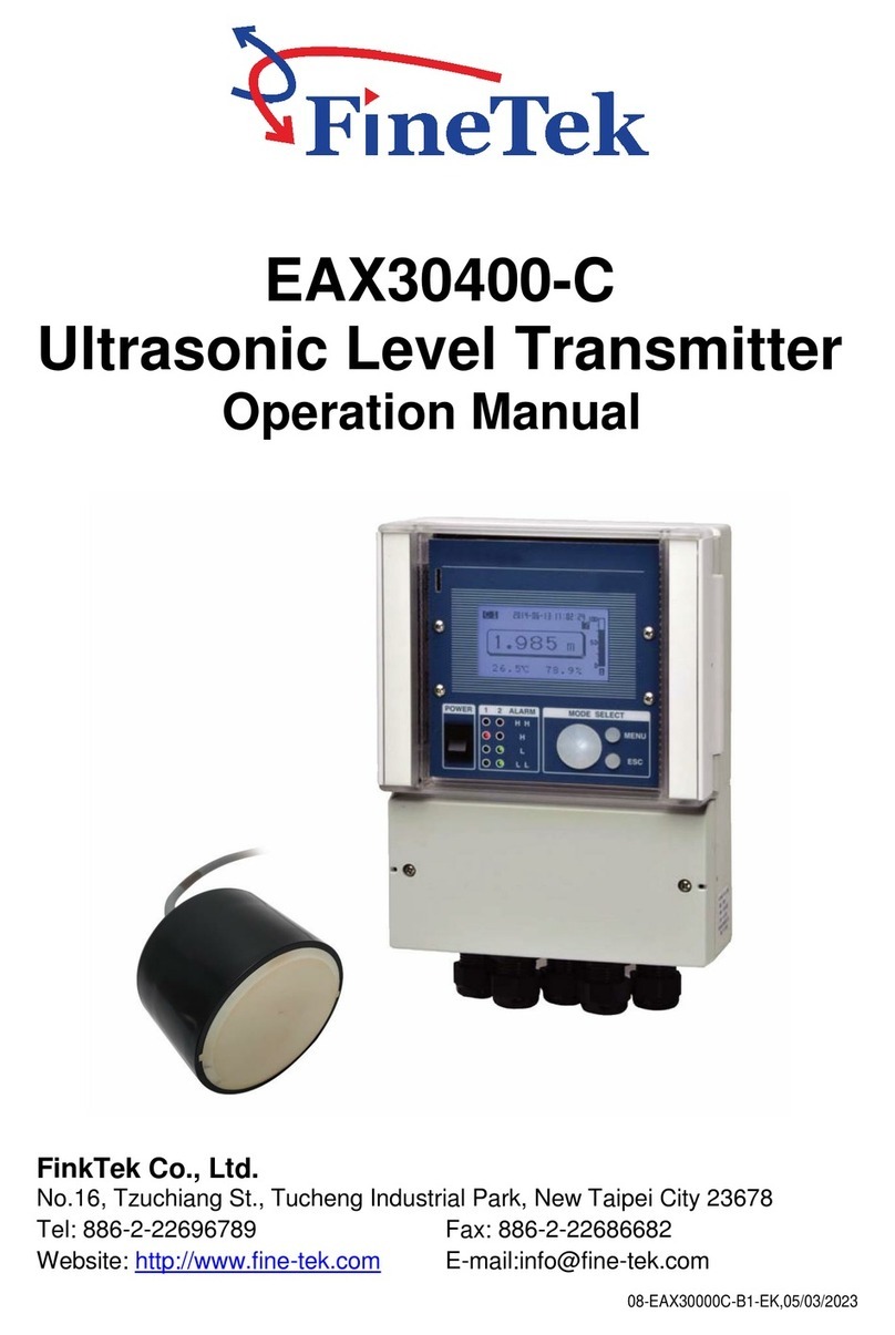
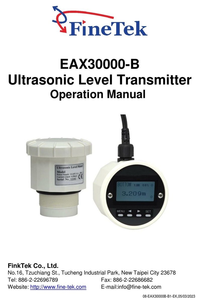
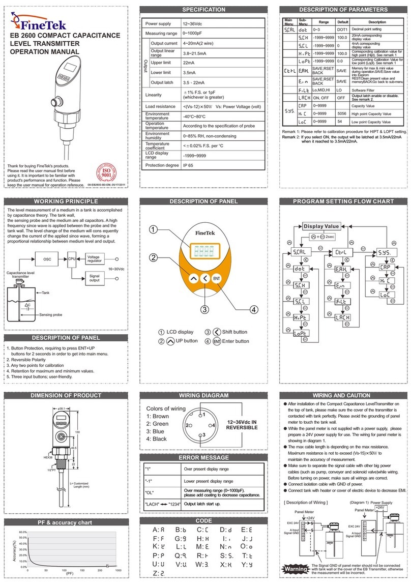
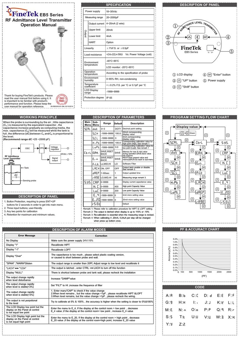
FineTek JFR-2 Series Technical manual

08-JFR2XX-B1-EK,11/08/2018
JFR-2 Series
FMCW Radar Level Transmitter
Operation Instruction
FineTek Co., Ltd
No.16, Tzuchiang St., Tucheng Industrial Park, New Taipei City 236, Taiwan
TEL: 886-2-22696789 FAX: 886-2-22686682
E-mail: info@fine-tek.com http://www.fine-tek.com

TABLE OF CONTENTS
1. INSTRUCTION .................................................................................................................... 1
2. GUARANTEE ...................................................................................................................... 2
3. INTRODUCTION ................................................................................................................. 3
4. SPECIFICATIONS ............................................................................................................... 4
5. INSTALLATION.................................................................................................................... 8
6. WRING INFORMATION ...................................................................................................... 10
7. CALIBRATION .................................................................................................................... 11
8. MENU SELECTION ............................................................................................................ 13
9. QUICK SETTINGS .............................................................................................................. 25
10 TABLE OF COMMUNICATION PARAMETERS ................................................................ 2 7

1. INSTRUCTION
Forbidden operation
Away from flammable materials or keep environment in electrical safety.
Wrong operation will result in electric shock.
Thank you for your purchasing for FineTek product. This user will introduce the product features, operations,
maintenance and troubleshooting to help user get familiar with product, avoid from the possible dangerous
use. Before operation, please carefully study the details of product. Extra support can find at www.fine-tek.com
or directly contact our representative by telephone and facsimile. On line revision will issue at web site and
not further inform. User can get newest support and download at www.fine-tek.com. In case of any
unexpected problem, don’t disassemble it by yourself or you will lose the product guarantee. Contact us, if
you have any question that hard to be defined.
Danger It indicates for wrong operation that has possible chance to cause disaster or danger to
user.
Attention It indicates for wrong operation that has possible chance to cause damage on
equipment .
Symbol Instruction
!
!
1

8-05, Plaza Azalea, Persiaran
Bandaraya, Seksyen 14, 40000
Shah Alam, Selangor, Malaysia
2. GUARANTEE
Maintenance Guarantee: All the products will get six months guarantee service since repair or replace
components. During six months, any fault caused in same will be serviced in free charge.
•Irresistible environment effects or natural disaster (earthquake, flood disaster, fire, lighting stroke, hurricane)
•Not properly use according to operation manual.
•Human-made damage (scratch, cutting, throwing down, hammering) or abnormal operation (over power
range, over ambient condition, over range operation, corrosion, watering, electric charge), non-proved third-
party device connection or expend, replace non-proved components or module.
All FineTek products will get one year guarantee in regular operation. Product within guarantee period will get
service and no charge for any nominal fee. User finds any defect during delivery process or not be broken by
wrong operation that can ask return or replace. In maintenance, user has the obligation to send all complete
parts back to FineTek in well carefully package. Over range operation, over charge or any abnormal
operation will excess out the guarantee range. Product not in guarantee period and condition will charge
necessary fee for the repair or replace.
•Expiry of the guarantee date.
Things below will not in guarantee coverage and will be charged service fee:
2
Company Address Telephon Fax
Taipei Headquarters
(Taiwan)
No.16, Tzuchiang St., Tucheng
Industrial Park, New Taipei City
23678
+886 2 2269 6789 +886 2 2268 6682
Fine automation
Co., Ltd. (China)
No. 451, Duhui Road,
Zhuanqiao Township, Minhang
District, Shanghai City 201109
+86 021 64907260 +86 021 6490 7276
Aplus FineTek
Sensor Inc.
355 S. Lemon Ave, Suite D,
Walnut, CA 91789 1 909 598 2488 1 909 598 3188
FineTek Pte Ltd.
(Singapore Branch)
37 Kaki Bukit Place,
Level 4 Singapore 416215 +65 6452 6340 +65 6734 1878
FineTek GmbH
(Germany Branch)
Bei den Kämpen 26
21220 Seevetal-Ramelsloh,
Germany
+49 (0) 4185 8083 12 +49 (0) 4185 8083 80
FineTek Co., Ltd.
(Indonesia Branch)
Ruko Golden 8 Blok H No.38
Gading Serpong, Tangerang
Indonesia 15810
+62 (21) 2923 1688 +62 (21) 2923 1988
FineTek Co., Ltd.
(Malaysia Branch) +603 5524 7168 +603 5524 7698
Service Network

3. INTRODUCTION
3
FEATURES
PRINCIPLE
FMCW Radar level transmitter is a non contact
measuring device, which is suitable for high temp.,
high pressure, and corrosive applications. It is
easy to install and free of maintenance, especially
for the high accuracy requirement environment.
Design formula
High voltage : IEC60947-2
Isolated resistance : IEC60092-504
Power supply change : IEC60092-504
Power supply failure : IEC60092-504
Electrical burst testing : IEC61000-4-4
Voltage DIPS : IEC61000-4-11
Humidity : IEC60068-2-30
High/Low temperature test : IEC60068-2-38
IP protection rating : IEC60529
TEST STANDARDS
LINEARITY DIAGRAM
FMCW radar adopts a high frequency signal,
which is emitted via an antenna and swipe
frequency increment by 0.5GHz during the
measurement, reflected by the target surface and
received at a time delay. The frequency difference,
which is calculated from the transmitting frequency
and the received frequency, which is directly
proportional to the measured distance (or material
surface).
The frequency difference then is processed by
Fast Fourier Transformation (FFT) to identify the
signal in Intermedium Frequency (IF). This FMCW
radar is innate with signal / noise enhancement
and filtering of echo-back via Phase-Lock Loop
(PLL) circuit that is the best solution for complex
environment and high accuracy measurement.
Accuracy
Distance to flange
0
-2
-4
-6
-8
-10
-12
12
10
8
6
4
2
cm
0.5m 5m 15m 20m
A0.2%
A0.2%
A3mm
A5mm
A10mm
A20mm
A0.4%
A0.4%
A30mm
A0.4%
-14
-16
ŸNon contact measurement
ŸCorrosive and toxic liquid, hydrocarbons, slurries
ŸNot affected by specific gravity, pressure,
temperature, viscosity, foam, and dust
Ÿ5 digits LCM display
ŸIndicate signal wave inside the silo.
ŸSelection of Different Measurement unit(m, cm,
mm, inch, ft, %, mA)
ŸMeasuring distance and actual level.
ŸLanguage selection of traditional Chinese,
simplified Chinese, English.
Ÿ4-20mA/ 4 wires/2 wires
ŸModbus RS-485 to enhance isolation and easy
for remote control.
ŸCE standards for isolation(EFT 2000V, B class
or better)
Ÿ4mA, 20mA output
Ÿ26GHz JFR2 series could measure all kinds of
material.

4
4. SPECIFICATIONS
Medium General liquid and solid
Dimensions
(Unit:mm)
Measuring range
Model
Accuracy
Repeatability
Ambient temperature
Operating temperature
Operating pressure
Frequency
Analog output
Protection rating
Local display
Housing material
Antenna type
Antenna material
Blind distance
Power supply
JFR-204
500mm
5 digits LCM display
Aluminum
Digital communication
Liquid 30m Solid 20m
A3 mm
-40~200 BC
0~40 bar
-40~90 BC(LCM<75BC)
K Band
4~20mA / 4 Wire
IP67
9.5~30Vdc
A1 mm
RS485 (Isolated)
Horn (43D)
SUS316+PTFE
Lens (56D)
PTFE
JFR-214
Min. Dielectric
constant (solid) 1.5
Min. Dielectric
constant (liquid) 1.4
General liquid /suitable for acid and
alkaline in liquid
Half-power beam width ±9°
Liquid 30m
217
f56
2"NPT or 2"PF
f98
1/2"PF
60
PTFE
f98
210
f43
1-1/2"PF
1/2"PF
60
PTFE

JFR-224 JFR-234
-40~200 BC
0~40 bar
-40~90 BC(LCM<75BC)
High gain horn (100)
SUS 316
K Band
4~20mA / 4 Wire
IP67
9.5~30 Vdc
5 digits LCM display
500 mm
A1 mm
RS485 (Isolated)
High gain horn (140)
Dimensions
(Unit:mm)
Measuring range
Model
Accuracy
Repeatability
Ambient temperature
Operating temperature
Operating pressure
Frequency
Analog output
Protection rating
Local display
Housing material
Antenna type
Antenna material
Blind distance
Power supply
Digital communication
P.S. For JFR-224 and JFR-234, customer can connect the compressed air with 1/8"PT thread
connector to avoid dust adhered.
Aluminum
A3mm @distance≤30m, A0.01% F.S.@distance>30m
Medium General liquid and solid
Min. Dielectric
constant (solid) 1.5
Min. Dielectric
constant (liquid) 1.4
Half-power beam width ±5°±3°
JFR-244
Liquid 40m Solid 30m
A3 mm
Liquid 70m Solid 50m Liquid 20m Solid 15m
Lens(43DS)
±10°
PTFE
Suitable For Long dlstance
measurement
Super dlstance
measurement
Corrosion type acid and
alkaline liquid
f98
476
1/2" PF
270
2"PF
compressed
air input
f98
369
f100
1/2" PF
162
2"PF
f98
190
1/2" PF
1-1/2" NPT
f43
43
compressed
air input
f140
5

Aluminum
Dimensions
(Unit:mm)
Model
Protection rating
Local display
Housing material
Antenna type
Antenna material
Blind distance
Power supply
Medium
Half-power beam width
217
f56
2"NPT or 2"PF
f98
1/2"PF
60
PTFE
f98
210
f43
1-1/2"PF
1/2"PF
60
PTFE
JFR-202 JFR-212
General liquid and solid
Liquid 20m Solid 10m
General liquid /suitable for acid and
alkaline in liquid
Liquid 20m
A5mm
-40~200BC
0~40 bar
-40~90BC(LCM<75BC)
K Band
4~20mA
IP67
24VdcA10%
A3mm
HART
5 digits LCM display
Horn (43D)
SUS 316 + PTFE
Lens (56D)
PTFE
±9°
500 mm
Min. Dielectric
constant (solid) 1.5
Min. Dielectric
constant (liquid) 1.4
Measuring range
Accuracy
Repeatability
Ambient temperature
Operating temperature
Operating pressure
Frequency
Analog output
Digital communication
6

Aluminum
Dimensions
(Unit:mm)
Model
Protection rating
Local display
Housing material
Antenna type
Antenna material
Blind distance
Power supply
Medium
Half-power beam width
1.5
1.4
-40~200BC
0~40 bar
-40~90BC(LCM<75BC)
K Band
4~20mA
IP67
24VdcA10%
A3mm
HART
5 digits LCM display
SUS 316 PTFE
500 mm
JFR-222 JFR-232
f98
369
f100
1/2" PF
162
f98
476
1/2" PF
270
f140
JFR-242
f98
190
1/2" PF
1-1/2" NPT
f43
2"PF
2"PF
43
General liquid and solid
Long dlstance
measurement
Super dlstance
measurement
Corrosion type acid and
alkaline liquid
Suitable For
Liquid 30m Solid 20m
A5 mm
Liquid 35m Solid 30m Liquid 15m
High gain horn (100D) High gain horn (140D)
±5°±3°±10°
Lens (43DS)
Min. Dielectric
constant (solid)
Min. Dielectric
constant (liquid)
Measuring range
Accuracy
Repeatability
Ambient temperature
Operating temperature
Operating pressure
Frequency
Analog output
Digital communication
compressed
air input
compressed
air input
A5mm @distance≤20m,
A0.025% F.S.@distance>20m
P.S. For JFR-222 and JFR-232, customer can connect the compressed air with 1/8"PT thread
connector to avoid dust adhered. 7

8
5. Installation
D
L
Diameter D (Inch) Length L (Inch)
Model
JFR-22X
JFR-23X
Diameter D (Inch) Length L (Inch)
D>100 L£150
D>140 L£270
1. JFR-20x can be hidden in the extension tube, the
recommendation of the tube diameter D and length L
are shown in the table.
3. JFR-22X and JFR-23X can be hidden in the extension
tube, the recommendation of the tube diameter D and
length L are shown in the table.
D
L
2. JFR-21x can be hidden in the extension tube, the
recommendation of the tube diameter D and length L
are shown in the table.
Diameter D (Inch) Length L (Inch)
D
L
D
L
2" L£100
4" L£200
5" L£300
6" L£400
4. theJFR-24x can be hidden in the extension tube,
recommendation of the tube diameter D and length L
are shown in the table.
Diameter D (Inch) Length L (Inch)
2" L£160
4" L£300
5" L£400
6" L£500
3" L£200
4" L£300
5" L£400
5. Installation recommendations are as follows :
(1) Antenna installation angle to be perpendicular to the
Horizontal.
(2) JFR installation position with the drum wall suggestions
Are as follows :
Installation location A should be less than 1/6D
Range with A relation is as follows :
a. H<10m, A>300mm
b. 10m<H<20m, A >600mm
c. H>20m, A>900mm
(3)Extended tube is suggested to do the welding process
from outside; welding process from inside, the bulges
might affect the signal transmission. The joint part of
extended tube cannot be less than “D”.
DL

9. Outdoor installation should take shade or rain-proof
measures.
vent hole
X
X
X
10. If drum internal agitator will have a strong vortex and
foam, drum must increase waveguide, the upper
waveguide drill vent holes to ensure the correctness of
the measured value.
11. Installation should be avoided in the feed inlet position,
avoid material interference or obstacles interference.
12. Installation should be avoided in the top center of the
arch or round barrel will cause multiple echo reflections.
X
Reflector
X
6. Radar installation should not be too close to the drum
wall, avoid the drum wall attachment material reflection
interference.
8. When obstructions inside the tank, tank be fitted with
eflectors, steer clear of the error echo reflected to the
receiver, causing radar miscalculation.
7. Radar installation not too close to the drum bracket to
avoid reflection is incorrect
X
9

10
6. WRING INFORMATION
Two ways to calibrate the JFR Series:
4-wire:
1. Display/Adjustment module
2. By pcbased fas soft ware
2-wire:
1. Display/Adjustment module
2. HART
Adjustment module is an adjustment tool with
4 buttons to click on. It also has a transparent
window to allow display reading.
[ ] Button
-Select Edit
-Select parameter
-Parameter
[ ] Button
-Increase
-Select
Power Supply: V+
: V-Power Supply
: I+ (4~20mA)Analog Output
: I- (4~20mA)Analog Output
: TR+ (RS485)Communication
: TR- (RS485)Communication
5
2
1
3
4
6
[ ] Button
-Enter Edit status
-Confirm Edit
-Confirm parameter
modification
[ ] Button
-Return
-Cancel
RS232 / USB Interface Interface
RS232/485
Converter
1
2
5
6
TR- TR+
POWER
DC24V
1
2
3
4
I+
POWER
DC24V
CALIBRATION
WIRING INFORMATION
I-
RS485 wiring
JFR Series and Indicator(External Power)
WIRING DIAGRAM
V+
V-
V+
V-
Panel Meter
JFR-2X4 JFR-2X2
1234 5 6 12
24V DC. 4-20mA Modbus
+
-
+
-
D+ D
-
24V DC
+
-
1
2
POWER
DC24V
V+
V-
5 digits LCM displat

11
7. CALIBRATION
4 wires:With display/adjustment module
2 wires: 1.With display/adjustment module 2. HART
Adjustment module is an adjustment tool with 4 buttons to click on. It also has a transparent window to allow
display reading.
CALIBRATION
[ ] Button
-Select Edit
-Select parameter
-Parameter
[ ] Button
-Increase
-Select
[ ] Button
-Enter Edit status
-Confirm Edit
-Confirm parameter
modification
[ ] Button
-Return
-Cancel
5 digits LCM display
24V DC. 4-20mA Modbus
+
-
+
-
D+ D
-
24V DC
+
-
4 Wires 2 Wires

12
Measurement
Setting 1 Low-level adjustment 1.1
Manual setting 1.2.1
Auto setting 1.2.2
Signal gain 3.1
Filter setting 3.2
Signal selection 3.3
Current 4.1
Display content 2.1
Manual setting 1.1.1
Auto setting 1.1.2
Distance 2.1.1
Distance 2.1.1.1
Percentage 2.1.1.2
Current 2.1.1.3
Material level 2.1.2.1
Percentage 2.1.2.2
Current 2.1.2.3
Material level 2.1.2
Set preserved signal 3.4.1
Reset 3.4.2
Select noise 3.5.1
Reset 3.5.2
Max current output 4.1.1
Min current output 4.1.2
River monitoring 1.6.1
Tank monitoring 1.6.2
Liquid 1.5.1
Powder 1.5.2
Background noise 3.4
Signal elimination 3.5
Signal erasure 3.6 Erase noise 3.6.1
Reset 3.6.2
Eliminate background signal 3.7.1
Reset 3.7.2
Signal threshold setting 3.8.1
Reset 3.8.2
Reset 4.2
Unit 4.3
Language 4.4
Cancel 4.2.1
Confirm 4.2.2
m 4.3.1
cm 4.3.2
mm 4.3.3
in 4.3.4
ft 4.3.5
ENGLISH 4.4.1
Traditional Chinese 4.4.2
Simplified Chinese 4.4.3
Display Setting 2
Echo Pattern 3
Options Setting 4
Connection
Setting 5
Machine Info 6
High-level adjustment 1.2
Range of blind area 1.3
Scale setting 1.4
Material setting 1.5
Environment setting 1.6
Display content 2.1
Background signal 3.7
Signal threshold 3.8
Dynamic range 3.9.1
Signal threshold 3.9
Signal threshold setting
Signal erasure
Background signal
Signal threshold setting
Dynamic range
3.9
Device address 5.1
Connection speed 5.2
4 wires
HART ON/OFF 5.1
Device address 5.2
Connection speed 5.3
2 wires

Press in the measuring screen to enter the echo pattern. You may also press to return to the
measuring screen.
Main Menu
Measurement setting.
Display setting
Echo pattern
Option setting
1
FineTek
16.272
M CM MM INCH FT % MA
FineTek
16.272
M CM MM INCH FT % MA
Measurement Setting
Low point adjustment
High point adjustment
Range of blind area
Measurement setting
1.1
Low point adjustment 1.1.1
Manual setting
Auto setting
Manual setting 1.1.1
04500
MM
13
1.1 Measurement Setting
8. MENU SELECTION
To enter the measuring screen from the main menu, press + for 3 seconds.
It is for setting the major parameters, such as high/low point adjustment, blind area and scale settings.
Press in the main menu, select Measurement Setting, and then press to make settings.
1.1.1 Manual setting
It is to input the low material level value (empty bin) manually. Press in the Low Point Adjustment menu
and select Manual Setting 1.1.1. Then, press to save the settings.
Input the distance required from the flange surface to the low point by using and (in the unit of mm).
After that, press to finish the manual setting for low point.
Measuring screen
Measuring screen
Echo pattern
1.1 Low point adjustment
TManual and auto settings are available for the low material level setting (empty bin). Press in the
Measurement Setting menu and select Low Point Adjustment 1.1. And then press to save the settings.

1.1.2 Auto Setting
Low point adjustment 1.1.2
Manual setting
Auto setting
Manual setting 1.1.2
43317
MM
Measurement setting
Low point adjustment
High point adjustment
Scope of blind area
Scale setting
1.2
Manual setting 1.2.1
00500
MM
Manual setting 1.2.2
43317
MM
High point adjustment 1.2.1
Manual setting
Auto setting
High point adjustment 1.2.2
Manual setting
Auto setting
14
The Auto Setting takes the material level value currently measured on site (based on the basis point of
the flange surface) as the low point value. Then press in the Low Point Adjustment menu and select
Auto Setting 1.1.2. Finally press to save the settings.
1.2 High Point Adjustment
Press to save the modification and finish the auto setting for low point.
Manual and auto settings are available for the high material level setting (full bin). Press in the
Measurement Setting menu and select High Point Adjustment 1.2. And then press to save the settings.
1.2.1 Manual setting
It is to input the high material level value (full bin) manually. Press in the High Point Adjustment menu
and select Manual Setting 1.2.1. Finally, press to save the settings.
Input the distance required from the flange surface to the high point by using and (in the unit of mm).
After that, press to finish the manual setting for high point.
1.2.2 Auto setting
The Auto Setting takes the material level value currently measured on site (based on the basis point of
the flange surface) as the high point value. Press in the High Point Adjustment menu and select Auto
Setting 1.2.2. Finally press to save the settings.
Press to save the modification and finish the auto setting for high point.

Measurement setting
Low point adjustment
High point adjustment
Scope of blind area
Scale setting
1.4
MM
Measurement setting 1.4
04500
15
Press to select Monitoring Mode. Press to save the settings and return to the Measurement
Setting menu, or press to return to the main menu.
Environment Setting
River monitoring
Tank monitoring
1.6.1
Measurement setting
Scope of blind area
Scale setting
Material characteristic
Environment setting
1.6
Material characteristics
Liquid
Powder
1.5.1
1.3 Scope of Blind Area
It refers to the distance beyond the detection scope of the product. This function doesn’t require setting.
Measurement setting
Low point adjustment
High point adjustment
Scope of blind area
Scale setting
1.3
1.4 Scale Setting
It is to input the tank height. Press in the Measurement Setting menu and select Scale Setting 1.4.
Then press to save the settings.
Input the scale range by using and (in the unit of mm). After that,press to save the settings and
return to the Measurement Setting menu. Finally press to return to the main menu.
1.5 Material Characteristics
Select the target material, liquid or powder. Press in the Measurement Setting and select Scale Setting
1.5. Then press to save the settings.
1.6 Environment Setting
Select radar measuring environment, river or tank. Press in the Measurement Setting menu and select
Environment Setting 1.6. And then press to save the settings.

16
Display contrast 2.2
51%
2.2 Display Contrast
Adjust the desired display contrast by using or , and press to save.
Main menu
Measurement setting
Display setting
Echo pattern
Option setting
3
Echo pattern
Signal gain
Filter setting
Signal selection
Background noise
3.1
Echo pattern
Signal gain
Filter setting
Signal selection
Background noise
3.2
回波圖形 3.1
LVL:0001 It is the default value without signal magnification.
LVL:0002 It means the signal is magnified by 2 times.
LVL:0003 It means the signal is magnified by 4 times.
LVL:0004 It means the signal is magnified by 8 times.
LVL:0005 It means the signal is magnified by 16 times.
LVL:0006 It means the signal is magnified by 32 times.
LVL:0007 It means the signal is magnified by 64 times.
Filter setting 3.2
20
Save
3. Echo Pattern
From the echo pattern, the user may observe the echo curve of the current signal and make the settings
obtain the correct echo value by processing various signals (signal gain, filter setting, signal selection,
background noise, signal elimination). Press in the main menu and select the echo pattern 3. Then,
press to save the settings.
3.1 Signal Gains
As shown in the echo pattern, when the echo signal is so weak that the display value is unstable without
interference from other noise, this function can be used to magnify the echo signal. Press in the Echo
Pattern menu and select Signal Gains 3.1. Finally, press to save the settings.
Select the magnification rate by using or . The magnification rate is displayed by LVL on the upper
right of the echo pattern (LVL is 0001 by default). A total of 7 levels are available. Press to save the
settings, as described below.
3.2 Filter Setting
This function is applied to the great fluctuation or bubble generated on the liquid surface, which causes
the echo signal to become unstable. It is used when the display value is unstable. Press in the Echo
Pattern menu and select Filter Setting 3.2. Then press to save the settings.
The default value is 10, which can be adjusted by pressing or . After the setting is finished,
press to save. If the display value is still unstable after the setting, increase the value for test again.

Reset
Cancel
Confirm
3.4.2.1
Echo pattern
Signal gains
Filter setting
Signal selection
Background noise
3.3
Echo pattern
Signal gains
Filter setting
Signal selection
Background noise
3.4
Background noise
Set retained signal
Reset
3.4.1
Background noise
Set retained signal
Reset
3.4.2
Flashing
cursor
Bar cursor
17
3.3 Signal Gains
As shown in the echo pattern, when the interference signal is stronger than the echo signal which may
result in misjudgment, the function can be used to select the echo signal to obtain the correct measurement
value. Press in the Echo Pattern menu and select Signal Selection 3.3. Finally, press to save the settings.
Use or to move the flashing cursor on the echo pattern to the target position of the echo signal.
Press to execute the echo signal to be selected, and then press to save the settings.
3.4 Background Noise
It is to eliminate the interference of the background noise, which is applicable to the empty bin. It can be
used to eliminate all fixed interference noise rather than the echo signal. Press in the Echo Pattern
menu and select Background Noise 3.4. Finally, press to save the settings.
3.4.1 Set Retained Signal
Press in the Background Noise menu and select Set Retained Signal. Finally, press to save the
settings.
Use or to move the bar cursor on the echo pattern to the target position of the echo signal.
Press to execute the echo signal to be selected, and then press to save the settings. Then, the
selected signal will be retained, while other signals will be filtered as background noise.
3.4.2 Set Retained Signal
It is used to reset the function of Set Retained Signal as the default value. Press in the Background
Noise 3.4 menu and select Reset 3.4.2. Finally press to save the settings.
3.4.2.1 Cancel
It is to cancel the reset function. Press in the Reset menu 3.4.2 and select Cancel 3.4.2.1. Finally,
press .

Reset
Cancel
Confirm
3.4.2.2
Reset
Cancel
Confirm
3.5.2.1
Echo pattern
Filter setting
Signal selection
Background noise
Signal elimination
3.5
Signal elimination
Noise selection
Reset
3.5.1
Signal elimination
Noise selection
Reset
3.5.2
Bar cursor
18
Reset
Cancel
Confirm
3.5.2.2
3.4.2.2 Cancel
It is to perform the reset function. Press in the Reset menu 3.4.2 and select Confirm 3.4.2.2. Finally,
press .
3.5 Signal Elimination
It can be used to eliminate all fixed interference noise rather than the echo signal. Press in the Echo
Pattern menu 3 and select Signal Elimination 3.5. Finally, press to save the settings.
3.5.1 Noise Selection
It can be used to eliminate all fixed interference noise rather than the echo signal. Press in the Signal
Elimination menu 3.5 and select Noise Selection 3.5.1. Finally, press to save the settings.
Use or to move the bar cursor on the echo pattern to the target position of the echo signal.
Press to execute the echo signal to be eliminated, and then press to save the settings.
3.5.2.1 Cancel
It is to cancel the reset function. Press in the Reset menu 3.5.2 and select Cancel 3.5.2.1. Finally,
press
3.5.2.2 Confirm
It is to perform the reset function. Press in the Reset menu 3.5.2 and select Confirm 3.5.2.2. Finally,
press
3.5.2 Reset
It is used to reset the function of Signal Elimination as the default value. Press in the Background
Noise menu 3.5 and select Reset 3.5.2. Finally, press to save the settings.
This manual suits for next models
10
Table of contents
Other FineTek Transmitter manuals
Popular Transmitter manuals by other brands
Novus
Novus RHT-XS instruction manual
Denon Professional
Denon Professional DN-500R Serial Command Protocol Guide
Decade
Decade MS-100 series instruction manual
Becker
Becker CentronicPLUS SWC541 PLUS Assembly and operating instructions
Kopp
Kopp 8114.0102.9 manual
NIVELCO
NIVELCO PiloTREK W-200 User and programming manual

