FineTek EB 2600 User manual
08-EB2600-B0-EM, 05/17/2011
Main
Menu
Sub-
Menu Range Default Description
0~3
-1999~9999
-1999~9999
DOT1
100.0
0
100.0
0.0
ON, OFF OFF
SAVE,RSET
BACK
SAVE,RSET
BACK
Lo,MID,HI
SAVE
SAVE
LO
1/2"PT
HEX38
22
49.5
130
L= Customized
Length (mm)
f38.1
2
2
2
2
2 Connect isolation cable with GND of power.
2 Connect tank with heater or cover of electric device to decrease EMI.
After installation of the Compact Capacitance LevelTransmitter on
the top of tank, please make sure the cover of the transmitter is
contacted with tank perfectly. Please avoid the grounding of panel
meter to touch the tank wall.
While the panel meter is not supplied with a power supply, please
prepare a 24V power supply for use. The wiring for panel meter is
showing in diagram 1.
The max cable length is depending on the max resistance.
Maximum resistance is not to exceed (Vs-15)H50W to
maintain the accuracy of measurement.
Make sure to separate the signal cable with other big power
cables (such as pump, conveyer and solenoid valve)while wiring.
Before turning on power, make sure all wirings are correct.
4
2
3
1
ENTENT
Power supply
Measuring range
Output current
Output
Output linear
range
Upper limit
Lower limit
Output latch
Linearity
Load resistance
Environment
temperature
Operation
temperature
Environment
humidity
Temperature
coefficient
LCD display
range
Protection degree
12~36Vdc
0~1000pF
4~20mA( )2 wire
3.8~21.5mA
22mA
3.5mA
3.5、22mA
A1% F.S. or 1pF
(whichever is greater)
<(Vs-12)H50W Vs: Power Voltage (volt)
-40BC~80BC
According to the specification of probe
0~85% RH, non-condensing
<A0.02% F.S. per BC
-1999~9999
IP 65
-1999~9999
-1999~9999
12~36Vdc IN
REVERSIBLE
1
2 4
3
Lower present display range
Over present display range
Over measuring range (0~1000pF).
please add coating to decrease capacitance.
Output latch start up.
"OL"
"LACH" "1234"
"1"
"-1"
G:
Q:
B:
L:
V:
H:
R:
C:
M:
W:
O:
E:
Y:
T:
J:
A:
K:
U:
F:
P:
Z:
I:
S:
N:
D:
X:
60.0%
50.0%
40.0%
30.0%
20.0%
10.0%
0.0%
0 50 100 150 200 1000
(PF)
Accuracy(%)
EB 2600 COMPACT CAPACITANCE
LEVEL TRANSMITTER
OPERATION MANUAL
Thank for buying FineTek's products.
Please read the user manual first before
using it. It is important to be familiar with
product's performance and function. Please
keep the user manual for operation refereuce.
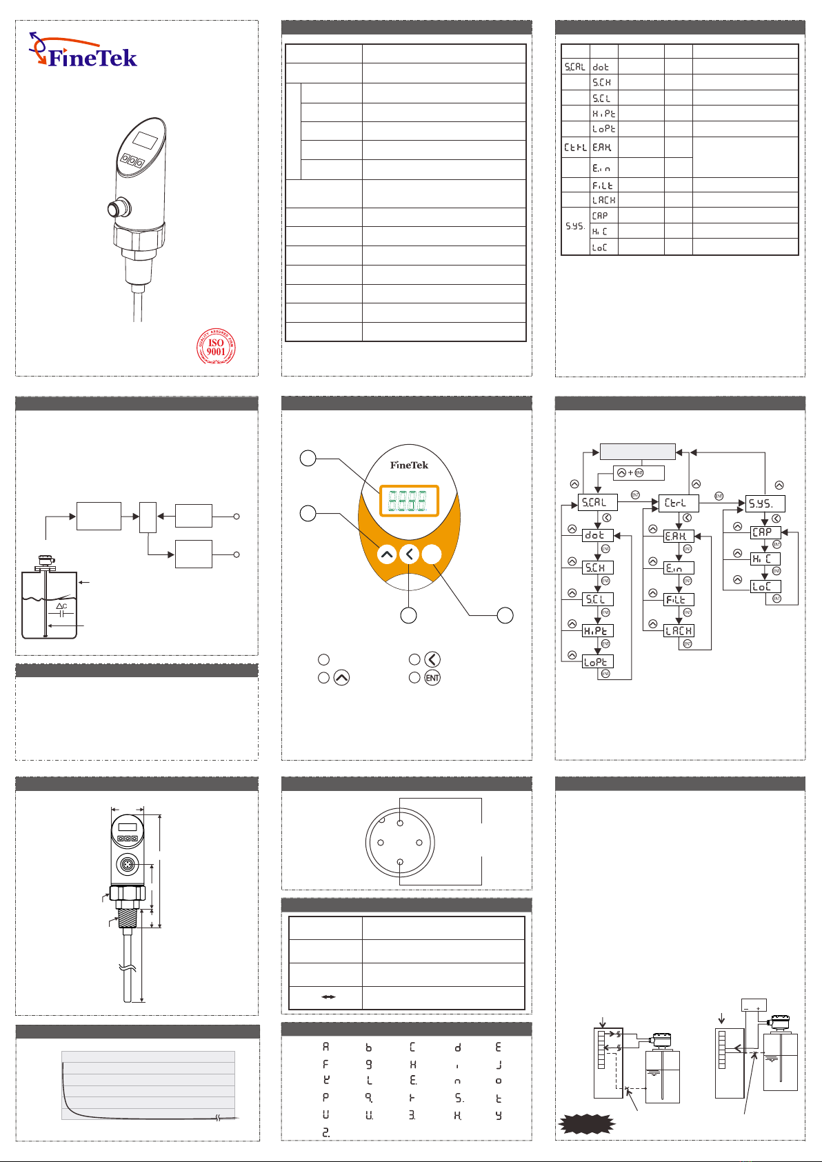
WORKING PRINCIPLE
The level measurement of a medium in a tank is accomplished
by capacitance theory. The tank wall,
the sensing probe and the medium are all capacitors. A high
frequency since wave is applied between the probe and the
tank wall. The level change of the medium will cons equently
change the current of the applied since wave, forming a
proportional relationship between medium level and output.
OSC CPU Voltage
regulator
Signal
output
Capacitance level
transmitter
Tank
Sensing probe
16~30Vdc
DESCRIPTION OF PANEL
1. Button Protection, requiring to press ENT+UP
buttons for 2 seconds in order to get into main menu.
2. Reversible Polarity
3. Any two points for calibration
4. Retention for maximum and minimum values.
5. Three input buttons; user-friendly.
DIMENSION OF PRODUCT WIRING DIAGRAM
ERROR MESSAGE
CODE
SPECIFICATION
DESCRIPTION OF PANEL
LCD display
UP button
1
2
Shift button
Enter button
4
3
Colors of wiring
1: Brown
2: Green
3: Blue
4: Black
PROGRAM SETTING FLOW CHART
WIRING AND CAUTION
Signal GND
[ Description of Wiring ]
2
3
4
5
6
7
8
1
+24V
EXC 24V
A Input
The Signal GND of panel meter should not be connected
with tank wall or the cover of the EB Transmitter, otherwise
the measurement will be incorrect.
(Diagram 1)
Panel Meter Panel Meter
Power Supply
Signal GND
2
3
4
5
6
7
8
1
EXC 24V
A Input
+24V
Warning
DESCRIPTION OF PARAMETERS
PF & accuracy chart
Decimal point setting
20mA corresponding
display value
4mA corresponding
display value
Corresponding calibration value for
high point (Hipt). See remark 1
Corresponding Calibration Value for
low point (Lopt). See remark 1
Memory for max & mini value
during operation.SAVE:Save value
into Eeprom
REST:Clean present value and
memoryBACK:Go back to sub-menu
Output latch enable or disable.
See remark 2.
Software Filter
Remark 1: Please refer to calibration procedure for HIPT & LOPT setting.
Remark If you select ON, the output will be latched at 3.5mA/22mA
when it reached to 3.5mA/22mA.
2:
Display Value
2sec
Capacity Value
High point Capacity Value
Low point Capacity Value
0~9999
0~9999 5056
0~9999 54

CALIBRATION PROCEDURESSETTING FLOWCHART FOR EACH FUNCTION
Standard Procedures:
1.SCH : Set the max display value corresponding to 20mA at SCH.
2.SCL : Set the min display value corresponding to 4mA at SCL.
3.HIPT : Input and save the corresponding value at HIPT, while the
medium is in high level.
4.LOPT: Input and save the corresponding value at LOPT, while the
medium in is in low level.
Completed Calibration
Example 1:
The lowest value sets at 0 and the output sets at 4mA.
The highest value sets at 100.0 and the output sets at 20mA
Calibration is done in empty and full tank.
Example 2:
The lowest value sets at 100.0 and the output sets at 4mA.
The highest value sets at 200.0 and the output sets at 20mA
It is calibrated at 10% of tank high and 90% of tank high. The 0%
of the total height of the tank is corresponded to 4mA, while the
100% of the total height of the tank is corresponded to 20mA.
Procedures of calibration for example 2
1. Input:
Dot=1, SCL=100.0,
SCH=200.0
(It can be adjusted anytime; Nothing is related with the status
of tank.)
2. To fill the medium till reaching to
the 10% height of the tank, go to
the LOPT setting and input the
value of 10.0 and then press
"ENT" "SAVE'' (Remark 2).
3. To fill the medium till reaching
to the 90% height of the tank,
go to HIPT setting and input
the value of 90.0 and then
press "ENT" "SAVE''
(Remark 3).
3. When the tank is full, go to
HIPT setting and input 100.0,
then press "ENT" "SAVE"
(remark 1).
Procedures of calibration for example 1
1.Input:
Dot=1, SCL=0.0
SCH=100.0,
(It can be adjusted anytime; Nothing is related with the status
of tank.)
2. When the tank is empty, go to
the LOPT setting and input 0.0,
then press "ENT" "SAVE"
(remark 1).
10%
Lowest Point
Highest Point
90%
Empty TankEmpty Tank Full TankFull Tank
Remark 1: Under the setting for Hipt & Lopt, press "ENT" to show
(screen flashing)
Press "ENT" button to save the value and then press "UP" button
to escape the setting.
Note 2: When Hipt or Lopt setting is over range, the LCD show
"Err", Please reset the value.
Compact Capacitance Level Transmitter is to press the three
( )
buttons UP, SHIFT, ENTER on display panel. Firstly, selecting
the setting menu then input value by using three buttons
showing below:
Selection
Escape button
Enter button
Swap button
Setting
Increment button
Position shift button
Confirmation button
Up button
SHIFT button
ENTER button
●Swap button is for swapping
to different menus, such as
from main menu to main
menu or from sub menu to
sub menu.
Enter button
●Confirmation button. After revising
the SCH value, press enter button
to save the revised value.
Flashing alternately
:Revise Parameters
:Save Parameters
1 342
123 4
SHIFT button
●Shift button is for entering a
sub menu from main menu
or doing a position shifting
after entering sub menu.
●Position shift button. After entering
revision mode, press this button to
shift into revisable position.
Flashing alternately
(Digit flashing means
the value is revisable.)
1234
12 43
Flashing alternately
1234
1230
●Increment button. After entering
revise mode, press this button to
increase the revisable value.
For example, changing SCH
value from "1230" to "1234" is to
press this button fourth.
UP button
●Up button is enable to escape
from revision mode or to
escape from sub menu to
main menu.
Display value
Setting
Value
Setting
Value
Setting
Value
Setting
Value
Setting
Value
1.
2.
3.
4.
。
5.
6.
7.
8.
The rod probe or cable probe (depending upon which one you
purchased ) should be parallel to the tank wall and be positioned
as close as possible to the tank wall. Make sure the medium
does not stick in between the probe and the tank wall.
If the tank is not electrically conductive, a metal strap should be
added outside of tank wall (fig. 1) for either liquid or non-liquid
medium. Or place a metal tube, usually made out of stainless
steel, around the rod (fig. 2) for liquid medium. This metal tube
should come with a vent hole at top of the tube to allow the
medium to go up inside of the tube.
If the container is irregular-shaped, such as a cylindrical, and the
medium is liquid with low viscosity, the rod should be placed
inside a metal tube with vent hole at the top. (Fig. 2)
For non-conductive medium of powder or granuules in a new or
empty tank, the cable probe should be fixed to the bottom of tank
with ceramic isolator (EB2100 Series. If the tank is not empty,
please use the EB2300 Series. (fig. 3)
Make sure to fix the rod probe or cable probe to the container
wall with non-conductive supporting material. If an agitator is in
place (see fig. 4). This will prevent the deformation of the rod
probe and tangling of the cable probe around the agitator.
If the medium is conductive, make sure to coat the rod probe or
cable probe with PVDF or PP material.
During the installation, the process connection should be
grounded. An installation without proper grounding will not
guarantee normal operation of the device later on.
When all electrical connections inside of a Capacitance Level
Transducer housing are finished, the housing cover and the
conduit opening should be sealed and tightened to prevent
moisture from soaking in.
(Fig. 2)
Vent hole
Rod probe
Tube
INSTALLATION
(Fig. 1)
Rod probe
Metal strap
(Fig. 3)
Cable probe
Ceramic isolator
(Fig. 4)
Isolate
supporter
Rod probe
Agitator
1.Read installation notice before calibration.
2.It is recommended to have the media touched probe
bottom when users calibrate lowest value for empty tank.
3.Doring calibration, pribe should be put into the tank.
Don't calibrate the product outside the tank.
4.Please keep at least 50% distance between HIPT and LOPT
to ensure accuracy. It is recommended to calibrate with
empty and highest level in the tank.
4mA
20mA
Tel 886-2-22696789
Email: info@fine-tek.com http://www.fine-tek.com
: Fax: 886-2-22686682
No.16, Tzuchiang St., Tucheng Industrial Park, New Taipei City 23678, Taiwan.
F i n e T e k C o .,L t d .
Other FineTek Transmitter manuals


Popular Transmitter manuals by other brands


Greystone Energy Systems
Greystone Energy Systems PS-2ADP Series Hardware installation guide

Transmitter Solutions
Transmitter Solutions Firefly3 FIRlll433TSD22K3 manual

Vivax Metrotech
Vivax Metrotech Loc-5ST Series manual

NVT
NVT NV-ET1801 Condensed Installation Guide

Burkert
Burkert SE58 S operating instructions

SILENTRON
SILENTRON 5150 manual


