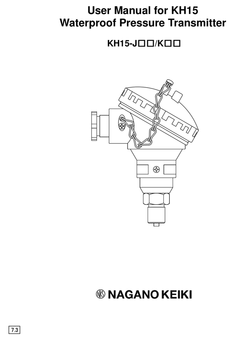
Nagano Keiki KH15-M Series User manual

TY-KH15-009A Ver. 3
○
エ
Type KH15 Pressure Transmitter
Instruction Manual
Jun.2023
8.1

TY-KH15-009A Ver. 3
Cautions for proper and safe operation
To use this product safely, please read this document and the instruction manual carefully.
Incorrect operation may cause malfunction, damage, or an accident.
The cautions and warnings in the document are indicated by the following:
Indicates that incorrect use may result in severe injury or loss of life.
Indicates that incorrect use may result in risk of injury or property damage.
Warning
・Do not apply pressure greater than the maximum allowable pressure.
This may cause damage or burst of the pressure element and result injury or
damage to the surroundings.
・Do not use this product to measure the object which causes gas/liquid
contact area to corrode.
This may cause damage or burst of the pressure element and release of the
measurement object. It will result in injury or damage to the surroundings.
・Do not apply excessive weight, vibration or shock.
This may cause damage or burst of the unit and release of the measurement
object. It will result in injury or damage to the surroundings.
・Use of a non designated power source may cause a fire or electrical shock.
・Use this device within the operating temperature range.
Using outside the range of operating temperature may cause malfunction or
damage of the product and result in injury or damage to surroundings.
・Perform wire connection according to the wire connection faceplate or the wire
connection instructions of the instruction manual.
Incorrect wire connection may cause injury or a fire.
・Use explosion -proof product where the place with risk of existence of explosive gas.
It may cause ignition or explosion.
・Where the measurement object is oxygen, use oil-proof product.
In case of ordinary product, there is a possibility that oil remains inside the
product. It may cause ignition or explosion by reaction with oxygen.
・Perform installation carefully according to the installation instructions of the
instruction manual.
・Do not alter this product. Also, do not remodel this product by adding new
functions.
Contact NKS for repairs.
・Since this product is a precision measuring instrument, keep the product as far away
from noise source as possible.
Also, remove noise from the power source by using noise filter, etc.
・For applications where serious damage or accidents may occur due to malfunction or
failure of this product, use several units to configure various protection circuits according
to the degree of seriousness of such damage or accidents, such as "1 out of 2", "2 x (1 out
of 2)", "2 out of 3", etc.
* If breakdown or malfunction of this product may directly threaten human life or it may
harm human body, please contact NKS in advance.
!
Warning
Caution
!
!

TY-KH15-009A Ver. 3
1/ 10
Contents
1. Introduction-------------------------------------------------------------------------------------- 2
2. Outline--------------------------------------------------------------------------------------------- 2
3. Structure of the model number---------------------------------------------------------------- 2
4. Specifications------------------------------------------------------------------------------------ 3
5. Outline diagram---------------------------------------------------------------------------------- 4
6. Wire connection diagram and examples of external connection------------------------ 5
(1) Wire connection---------------------------------------------------------------------------- 5
(2) Examples of external connection--------------------------------------------------------- 5
7. Operating principle------------------------------------------------------------------------------ 6
8. Precautions for use
(1) Installation----------------------------------------------------------------------------------- 7
(2) Cable specifications------------------------------------------------------------------------ 7
(3) Cautions for transportation and control-------------------------------------------------- 7
(4) Cautions for storage----------------------------------------------------------------------- 8
9. Operation------------------------------------------------------------------------------------------ 8
10. Maintenance and adjustment
(1) Maintenance--------------------------------------------------------------------------------- 8
(2) Adjustment--------------------------------------------------------------------------------- 9
(3) Countermeasures against noise----------------------------------------------------------- 10
11. Warranty-------------------------------------------------------------------------------------------10
12. Others---------------------------------------------------------------------------------------------- 10

TY-KH15-009A Ver. 3
2/ 10
1. Introduction
Confirm the specification of the purchased model.
Wrong pressure range, power supply or output may cause an accident. Make sure to use appropriate model
for the specification and use the product with proper wiring in an appropriate environment.
2. Outline
This product is a compact and robust pressure transmitter with semiconductor strain gauge in the pressure
detection part.
Standard outputs are "4 to 20mADC", "0 to 5VDC" and "1 to 5VDC". The product has an adjustment
window on the side surface which allows zero / span adjustment by removing elastic cover.
3. Structure of the model number
KH15 –M □□
Sealing type
3 : O ring type
4 : Fully welded type (SUS630(17-4PH))
6 : Fully welded type (Co-Ni alloy)
Connecting screw 2 : G1 / 4B K : 1 / 4 NPT
3 : G3 / 8B L : 3 / 8 NPT
4 : G1 / 2B M : 1 / 2 NPT
6 : R1 / 8
7 : R1 / 4
8 : R3 / 8
9 : R1 / 2
Type
Cable type:
External adjustment type

TY-KH15-009A Ver. 3
3/ 10
4. Specifications
Model number
KH15-M□3
KH15-M□4
、
M□6
Pressure sensor sealing type
O ring type
Welding type
Pressure range*1 0 to 0.1, 0 to 0.3, -0.1 to 0 MPa
-0.1 to 0.1 , -0.1 to 0.3 MPa
-0.1 to 0.5 => -0.1 to 2 MPa
0 to 0.5 => 0 to 100 MPa
Maximum allowable pressure
Twice as high as the pressure range Twice as high as the pressure range
(1.5 times high for 35,50MPa.
1.2 times high for 70,100MPa)
Power-supply voltage 24VDC ± 10%or 12VDC ± 10%, 15 VDC± 10%(Only power-supply
voltage can be selected)
Output type 4 to 20 mADC (Load resistance 500 Ωmax.)
1 to 5VDC (Load resistance10 kΩmin.)
0 to 5VDC (Load resistance 10 kΩmin.)
Accuracy
(Including linearity,
hysteresis, repeatability)
・± 1% F.S. ・± 0.25%F.S .*1
(Pressure range: 3.5 to 20MPa)
・± 0.5%F.S.
(Pressure range: 0.5 to 50MPa)
・
± 1.0% F.S
Operating temperature range
-20 to 70
℃
(No freezing nor condensation allowed)
*2
Storage temperature range
-30 to 80
℃
(No freezing nor condensation allowed)
Temperature characteristics ・Where accuracy is " ± 0.25% F.S." => ± 0.025% F.S. /℃(For both
zero point and span)
・Where accuracy is "± 0.5% F.S." => ± 0.05% F.S. /℃(For both zero
point and span)
・Where accuracy is "± 1.0% F.S." => ± 0.1% F.S. /℃(For both zero
point and span)
Responsiveness
1 ms or shorter
Liquid contact material Diaphragm : SUS630 (17-4PH)
Fitting : SUS316
O ring : NBR (Standard)
: EPDM
: Fluorine
: Chloroprene
KH15-M□4
Diaphragm : SUS630(17-4PH)
Fitting : SUS316
KH15-M□6
Diaphragm : Co-Ni alloy
Fitting : SUS316
Screw size G1 / 4B, G3 / 8B, G1 / 2B, R1 / 8, R1 / 4, R3 / 8, R1 / 2,
1 / 4 NPT, 3 / 8NPT, 1 / 2 NPT
(However, R screws and NPT screws are exclusively for the pressure range,
50 MPa or less)
Case structure
Drip-proof type 2 (IP52)
Weight
Approx. 210 g (Including 2 m - cable)
CE Marking
*3
EMC Directive
*3
, RoHS Directive
UKCA Marking
*3
EMC SI 2016 No.1091
*3
, RoHS SI 2012 No.3032
*1 : Model number KH15-M□6 and output type "0 to 5VDC" do not support the accuracy "± 0.25%F.S.".
*2 : However, in case of "0.1MPa or less", temperature range is 0 to 70℃.
Where temperature of the liquid contact area may reach 70℃(in case of steam, hot water and etc.),
make sure the temperature does not exceed 70℃by using pipe syphon , etc.
Where the temperature of the low-temperature fluid such as cold water is measured, take
countermeasures for dew condensation prevention.
*3: Before use, connect the product to an indoor power distribution network that is not affected by
lightning surge voltages and power system switching transients.

TY-KH15-009A Ver. 3
4/ 10
5. Outline diagram

TY-KH15-009A Ver. 3
5/ 10
6. Wire connection diagram and examples of external connection
(1) Wire connection
2-wire system 3-wire system
Wire color : Red Power supply(+)
Wire color: Red Power supply(+)
Wire color : White Power supply(-) Wire color : White COM
Wire color : Green Output
(2) Examples of external connection
e.g. 1) 2-wire system (4 to 20m ADC)
e.g. 2) 3-wire system (1~5VDC, 0~5VDC)
* When connecting equipment which may generate surge from the same power supply, connect a varistor
etc. to protect KH 15.

TY-KH15-009A Ver. 3
6/ 10
7. Operating principle
The pressure receiving part of this product is a diaphragm which converts pressure into strain. The amount
of the strain is detected by the semiconductor strain gauge.
The detection circuit is the full bridge type whose four sides consist of semiconductor strain gauge. From
this bridge circuit, electric signals proportional to the strain are obtained. Then by the signal conversion
shown below, DC electricity or DC voltage is transmitted.
(1) Block figure
(2) Example of a structure of the above figure (4 to 20 mADC output)

TY-KH15-009A Ver. 3
7/ 10
8. Precautions for use
(1) Installation
1) Where the product is connected to the pressure line, DO NOT tight the main body of the case with pipe
wrench, etc.
For installation, make sure to use hexagonal part of connecting screw
2) When installing to pressure line, DO NOT install the product while liquid is filled up in the pipe.
Since liquid is incompressible, tightening a connecting screw may generate high pressure and
instrument failure.
When installing to the existing pressure line or in the case of replacement, drain the liquid inside the
piping connection side and install the product with leaving air of about 15 to 20 mm.
3) Although this product has high vibration resistance, since this product is a measuring instrument, be
careful not to apply severe vibration.
Caution
・
Use this transmitter at an ambient temperature of - 20 to 70
℃
. (For 0 to 0.1MPa or
less, use it at 0 to 70℃)
・Secure a space wide enough to allow maintenance and adjustment.
・Where temperature of the liquid contact area may reach 70℃(in case of steam, hot
water and etc.), make sure the temperature does not exceed 70℃by using pipe
syphon
, etc. Also, if this transmitter is installed directly within the piping of low
temperature fluid, it may cause condensation on the detection sensor part and result in
failure. Make sure to take countermeasures against condensation.
(2) Cable specifications
Where cable sheath is removed, in case of current output (2-wire type), there are green and blue
wires besides red and white wires since cable main body consists of 4 wires. However, those green
and blue wires are not used (No inside connection).
In case of voltage output (3-wire type), there is blue wire besides red, white, and green wires.
However, blue wire is not used. (No inside connection)
Specifications of cables are as follows:
Ambient
temperature
Conductor
External diameter of
a cable (mm)
Cross-
section
area (mm2)
Structure
(Number of
cables / mm)
Shield cable (Standard) -20 to 60℃
0.2
(AWG24)
7 / 0.18 Φ 6.2
Heat-resistant cable -20 to 105℃
0.3
(AWG22)
12 / 0.18 Φ 6.0
Cold-resistant cable -40 to 80℃
0.3
(AWG22)
12 / 0.18 Φ 6.0
(3) Cautions for transportation and control
1) Cautions for transportation
Since this product is a precision measuring instrument, pay enough attention when transporting
the product. Drop or shock may cause a fatal damage.
2) Cautions for unpacking
Before unpacking, check the appearance of the package.
When unpacking, handle the package with care.
When bringing out the product from the packaging box, be careful not to drop the product.
After unpacking, check if there is any damage on the external surface and the product type is
correct as it is ordered.
If any abnormality is found, contact the distributor or NKS sales office.

TY-KH15-009A Ver. 3
8/ 10
(4) Cautions for storage
Cautions
To avoid failures or damages, do not store this product in the places where:
・exposed to water
・susceptible to adverse effects due to air pressure, temperature, humidity, ventilation,
sunlight, particles, salt or sulfur in the air.
・exposed to inclination, vibration or shock (including during transportation)
・exposed to chemicals (chemicals' storage area) or gas
・
exposed to direct sunlight or high temperature in a car, etc.
9. Operation
(1) Check whether the wire connection is correct before powering on.
(2) Make sure to spend about 5-minute (or more) warming up time after powered on before starting main
operation.
10. Maintenance and adjustment
(1) Maintenance
This product rarely needs maintenance since it does not have any movable part in the detection part
due to its structure. However, depending on its usage status, appropriate maintenance is required.
Typically, regular check-ups twice a year is recommended.
The following is a check list for the regular check-ups for your reference.
[List of regular check-up items]
- Appearance
- Corrosion status of pressure inlet
- Insulation resistance between each terminal and the case (100 MΩor more at 50 VDC)
- Re-tightening of connecting screw
- Output check by a reference pressure gauge
Cautions
・
Avoid electrostatic-charge.
When cleaning this instrument, use a soft damp cloth.
・DO NOT use thinner nor benzene which causes deterioration or failure.

TY-KH15-009A Ver. 3
9/ 10
(2) Adjustment
This product allows output adjustment by removing elastic cover on the side surface.
If the elastic cover is removed, the zero point / span adjustment trimmer appears.
1) Zero-point adjustment
Zero-point adjustment is performed by rotating zero-point adjustment trimmer with slotted
screwdriver. However, the adjustment method differs between positive pressure range and
compound pressure range as follows:
[Positive pressure range]
Adjust the output in air-ventilated (unpressurized) status to 4 mADC for current output, 1
VDC or 0 VDC for voltage output.
[Compound pressure range]
Output value in air-ventilated status is calculated according to the following formula.
- In case of current output (4 to 20 mADC)
[Output in air-ventilated status (mA)]
= [16mA] / ([Upper limit output in the range] - [ - 0.1MPa]) x 0.1+[4mA]
e.g.) 0.5 MPa, Compound pressure range: 6.67mA,
1.0 MPa, Compound pressure range: 5.45mA
- In case of voltage output (1 to 5 VDC)
[Output in air-ventilated status (V)]
= [4V] / ([Upper limit output in the range] - [ - 0.1MPa]) x 0.1+[1V]
e.g.) 0.5 MPa, Compound pressure range: 1.667V,
1.0 MPa, Compound pressure range: 1.364V
- In case of voltage output (1 to 5 VDC)
[Output in air-ventilated status (V)]
= [5V] / ([Upper limit output in the range] - [ - 0.1MPa]) x 0.1+[1V]
e.g.) 0.5 MPa, Compound pressure range: 0.833V,
1.0 MPa, Compound pressure range: 0.454V
2) Span adjustment
Do not try to perform span adjustment if you do not have a reference pressure gauge.
The method to perform span adjustment with a reference pressure gauge is as follows:
Please note that if the span adjustment trimmer is rotated, zero point is also changed.
a. Adjust zero-point output as described in "1) Zero point adjustment". (Releasing applied
pressure)
b. Apply the upper limit pressure of the rated pressure range. Then adjust span output to 20
mADC for current output, 5 VDC (or span value) for voltage output with the span
adjustment trimmer.
c. Repeat a. and b. alternately for few times to adjust zero point and span.

TY-KH15-009A Ver. 3
10/ 10
(3) Countermeasures against noise
Noise problems are complicated and often difficult to solve theoretically. Countermeasures are mostly
incomplete.
If measured values fluctuate from time to time or differ from the actual pressure value, they may be
affected by noise.
If noise is overlapped on the power supply lines, find out where the noise comes from, and provide
appropriate measures at the source of noise. If the noise is constant, use of a noise filter is effective. It
is also important to use other power lines that are free from noise.
Noise may be introduced to signal lines through external induction. It is necessary to provide suitable
measures, such as moving the noise source to a remote place, using a magnetic or antistatic shield.
These countermeasures also apply to surge.
11. Warranty
If the delivered products within the warranty period (within one year from the delivered date) are
determined to be non-conforming products according to "Defects due to the design or manufacturing by
NKS", they are repaired or replaced with conforming products free of charge.
However, note that the following cases are excluded.
(1) Where the delivered products are disassembled, altered or where their parts are replaced or new
function is added by the customer or any third party.
(2) Where directions described in the instruction manual or catalog are not observed.
(3) Where the non-conformance is caused by deterioration due to use, natural disaster, fire or other
force majeure events.
(4) The secondary damage caused by non-conformance of the products including the above.
Whether the customer has recognized a miss handling by the customer himself/herself, where any
apparent evidence of deformation, abrasion, burnout, etc. is seen on parts, they shall be excluded
from the warranty scope and the cost shall be paid by the customer.
12. Others
This operation manual does not cover all details of the instrument. Also, this manual is not intended to
cover all the related items encountered in installation or maintenance. If you require more detailed
information or if your requirements do not match the intentions of the design, please make enquiries to
NKS.
Some of the information in this instruction booklet may change without notice due to revisions, etc.
Website: https://www.naganokeiki.co.jp/?lang=en
Headquarters
30-4, Higashimagome 1-chome, Ota-ku,Tokyo,
Japan 143-8544
This manual suits for next models
4
Table of contents
Other Nagano Keiki Transmitter manuals
Popular Transmitter manuals by other brands

HumanTechnik
HumanTechnik lisa combi II operating instructions

Flo
Flo TRACER 1000 3G LTT1-3G operating instructions

Artel
Artel DigiLink DLC150E Installation and operation manual

MuxLab
MuxLab SE-000857-C Quick installation guide

Westlock Controls Corporation
Westlock Controls Corporation DEPIC 2 Installation and operation manual

Comnet
Comnet FVT10C1(M,S)1/M Series Installation and operation manual