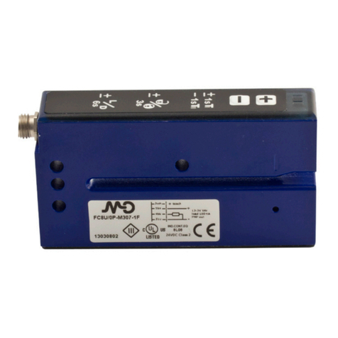
FINMASI Micro Detectors FC7 Series User manual

FC7
Manuale d’installazione - CAT8BFC1362302 - ITA - Creato: 12/03/2013
CONTENUTO DELLA CONFEZIONE
• Manuale di installazione
FORCELLA OPTOELETTRONICA
RILEVAMENTO ETICHETTE
SCHEMI ELETTRICI DELLE CONNESSIONI
uscita PNP
KEY:
BN = marrone;
BK = nero;
BU = blu;
WH = bianco
DIMENSIONI
LEGENDA
1LED giallo, acceso quando le uscite sono allo stato 1 (passante)
2LED rosso: Blocco tastiera e impostazioni
3/4 Pulsante regolazione +/–
CONNETTORI
M8 4 pin
ATTENZIONE Questo prodotto NON è un componente di sicurezza e NON deve esse-
re usato in applicazioni di salvaguardia della sicurezza delle persone.
Dichiarazione di conformità
M.D. Micro Detectors S.p.A. con Unico Socio dichiara sotto la propria responsabilità che questi prodotti
sono conformi ai contenuti della direttiva CEE: 2004/108/CE e ai successivi emendamenti.
M.D. Micro Detectors S.p.A.
con Unico Socio
Strada S. Caterina, 235
41122 Modena Italy
Tel. +39 059 420411
Fax +39 059 253973
www.microdetectors.com
Italian Sensors Technology
a company of
Assicurarsi che la tensione di alimentazione sia correttamente
stabilizzata con una ondulazione residua (ripple) compresa
all’interno dei dati di catalogo.
Nel caso che il rumore indotto dalle linee di potenza risulti
superiore a quello previsto dalla normativa CE (immunità ai
disturbi), separare i cavi del sensore dalle linee di potenza e
di alta tensione ed inserire il cavo in una canalina metallica
connessa a terra. E’ consigliabile inoltre, collegare il sensore
direttamente alla sorgente di alimentazione e non a valle di
altri dispositivi. Per estendere i cavi di alimentazione e usci-
ta utilizzare un cavo avente conduttori di sezione minima di
1 mm2. Il limite di estensione in lunghezza è 100 m (riferiti a
tensione minima e corrente al carico di 100 mA). Come d’uso
in ambiente industriale, si consiglia l’utilizzo di schermature
dei cavi di collegamento al ne di prevenire possibili disturbi
sui dispositivi provocati da campi elettromagnetici indotti. Non
esporre la testa del sensore ad acqua calda > 50 °C, vapore,
acidi o solventi. Per la pulizia della faccia attiva del sensore
usare un panno umido e asciugare.
• Sensore a forcella per etichette opache
con uscita a connettore M8 4 poli
• Modelli con regolazione manuale
tramite pulsanti +/- e teach-in dinamico
ed esterno
• Emissione a infrarossa
• Corpo di ridotte dimensioni facilmente
posizionabile
• NPN o PNP, Lo/Do congurabile
• Ampiezza fessura di rilevamento
Larghezza 3mm
• Profondità fessura di rilevamento 42mm
• Frequenza di commutazione 10kHz
• Corpo in materiale termoplastico IP65
AVVERTENZE
Modelli
LED infrarosso con modulazio-
ne della luce
FC7I/**-**-**
2 mm
42 mm
200 m/min
+/- 50 um a 150 m/min
12 … 24 Vdc (protezione
all’inversione di polarità)
10%
35 mA
100 mA
< 2 V @ IL=100 mA
10 KHz
Protezione inversione di
polarità
Protezione dell’uscita al
corto-circuito
-20 … +60 °C
-30 … +80 °C
2 mm
3 mm
50 us max
SPECIFICHE TECNICHE
2 Wh
3 Bu
4 Bk
1 Bn
+
-
-
+
Teach & N.O - N.C.
Normal Operation
Digital Output
2 Wh
3 Bu
4 Bk
1 Bn
-
+
2 Wh
3 Bu
4 Bk
1 Bn
+
-
-
+
Light On
Dark On
Digital Output
3 Bu
4 Bk
1 Bn
-
+
Digital Output
2 Wh +
-
Light On
Dark On
3 Bu
2 Wh
1 Bn
-/~ -/~
+/~ +/~
Common
5 Gr
4 Bk Digital Output NO
Digital Output NC
2 Wh
3 Bu
4 Bk
1 Bn
2 Wh
3 Bu
4 Bk
1 Bn
-
+
Double Digital Output
NO NC
2 Wh
3 Bu
4 Bk
1 Bn
-
+
Double Digital Output
NO
NC
1234
A
B
C2 Wh
3 Bu
4 Bk
1 Bn
+
-
-
+
Teach & N.O - N.C.
Normal Operation
Analog Output
2 Wh
3 Bu
4 Bk
1 Bn
-
+
Analog Output
2 Wh
3 Bu
4 Bk
1 Bn
-
+
Digital Output
4 Bk
3 Bu
2 Wh
1 Bn
-
+
Digital Output
2 Wh
3 Bu
4 Bk
1 Bn
-
+
Double Digital Output
2 Wh
3 Bu
4 Bk
1 Bn
-
+
Double Digital Output
D2 Wh
3 Bu
4 Bk
1 Bn
-
+
Digital Output
4 Bk
3 Bu
2 Wh
1 Bn
-
+
Digital Output
Analog Output
Analog Output
E
F
2 Wh
3 Bu
4 Bk
1 Bn
+
-
-
+
Teach & N.O - N.C.
Normal Operation
Analog Output
2 Wh
3 Bu
4 Bk
1 Bn
-
+
check +
check -
2 Wh
3 Bu
4 Bk
1 Bn
-
+
Double Digital Output 4 Bk
3 Bu
1 Bn
-
+
Digital Output
4 Bk
3 Bu
1 Bn
-
+
Digital Output
2 Bu
1 Bn
Digital Output
~
~
2 Wh
3 Bu
4 Bk
1 Bn
+
-
-
+
Teach
Teach
Normal Operation
Normal Operation
Digital Output
3 Bu
4 Bk
1 Bn
-
+
Digital Output
2 Wh
+
-
G
2 Wh
3 Bu
4 Bk
1 Bn
-
+
Selectable PNP / NPN Digital Output
H
uscita NPN
2 Wh
3 Bu
4 Bk
1 Bn
+
-
-
+
Teach & N.O - N.C.
Normal Operation
Digital Output
2 Wh
3 Bu
4 Bk
1 Bn
-
+
2 Wh
3 Bu
4 Bk
1 Bn
+
-
-
+
Light On
Dark On
Digital Output
3 Bu
4 Bk
1 Bn
-
+
Digital Output
2 Wh +
-
Light On
Dark On
3 Bu
2 Wh
1 Bn
-/~ -/~
+/~ +/~
Common
5 Gr
4 Bk Digital Output NO
Digital Output NC
2 Wh
3 Bu
4 Bk
1 Bn
2 Wh
3 Bu
4 Bk
1 Bn
-
+
Double Digital Output
NO NC
2 Wh
3 Bu
4 Bk
1 Bn
-
+
Double Digital Output
NO
NC
1234
A
B
C2 Wh
3 Bu
4 Bk
1 Bn
+
-
-
+
Teach & N.O - N.C.
Normal Operation
Analog Output
2 Wh
3 Bu
4 Bk
1 Bn
-
+
Analog Output
2 Wh
3 Bu
4 Bk
1 Bn
-
+
Digital Output
4 Bk
3 Bu
2 Wh
1 Bn
-
+
Digital Output
2 Wh
3 Bu
4 Bk
1 Bn
-
+
Double Digital Output
2 Wh
3 Bu
4 Bk
1 Bn
-
+
Double Digital Output
D2 Wh
3 Bu
4 Bk
1 Bn
-
+
Digital Output
4 Bk
3 Bu
2 Wh
1 Bn
-
+
Digital Output
Analog Output
Analog Output
E
F
2 Wh
3 Bu
4 Bk
1 Bn
+
-
-
+
Teach & N.O - N.C.
Normal Operation
Analog Output
2 Wh
3 Bu
4 Bk
1 Bn
-
+
check +
check -
2 Wh
3 Bu
4 Bk
1 Bn
-
+
Double Digital Output 4 Bk
3 Bu
1 Bn
-
+
Digital Output
4 Bk
3 Bu
1 Bn
-
+
Digital Output
2 Bu
1 Bn
Digital Output
~
~
2 Wh
3 Bu
4 Bk
1 Bn
+
-
-
+
Teach
Teach
Normal Operation
Normal Operation
Digital Output
3 Bu
4 Bk
1 Bn
-
+
Digital Output
2 Wh
+
-
G
2 Wh
3 Bu
4 Bk
1 Bn
-
+
Selectable PNP / NPN Digital Output
H
Materiale termoplastico
(PA12)
M8, 4-pin
Approx. 35 g
IP 65
FUNZIONAMENTO
2 4
Supply (+) - BN Supply (-) - BU
Teach - WH Output - BK
3
3s
6s
L
D
T
1s
1sT
1
2
3
Yellow LED, “ON” when the outputs are set to 1 (conducting)
LED giallo, acceso quando le uscite sono allo stato 1 (passante)
Red LED: settings and keypad lock
LED rosso: impostazioni e blocco numerico
Setting +/– push button
Pulsante regolazione +/–
4
Light (NC)
Dark (NO)
en
it
en
it
en
it
3
4
1
2
3s
6s
L
D
T
1s
1
sT
63,6
57,2
10
5 5,2 2,8
3
9
42
52
Ø4,2
19
3
25
14
3
mm
3s
6s
L
D
T
1s
1sT
1
2
3
Yellow LED, “ON” when the outputs are set to 1 (conducting)
LED giallo, acceso quando le uscite sono allo stato 1 (passante)
Red LED: settings and keypad lock
LED rosso: impostazioni e blocco numerico
Setting +/– push button
Pulsante regolazione +/–
4
Light (NC)
Dark (NO)
en
it
en
it
en
it
3
4
1
2
3s
6s
L
D
T
1s
1
sT
63,6
57,2
10
5 5,2 2,8
3
9
42
52
Ø4,2
19
3
25
14
3
mm
3 mm
Emissione
Minima lunghezza
dell’etichetta
Distanza minima tra
2 etichette
Distanza di rilevazio-
ne nominale Sn
Profondità Fessura di
Rilevamento
Portata massima
Accuratezza del
rilevamento
Tensione di alimenta-
zione Ue
Massima ondulazio-
ne residua
Assorbimento a vuoto
Corrente di carico
Caduta di tensione in
uscita Ud
Frequenza di commu-
tazione f
Protezioni elettriche
Temperatura ope-
rativa
Temperatura di
stoccaggio
Ritardo alla
disponibilità
Materiali
Tipo di connettore
Peso
Grado di Protezione
(DIN 40 050)
Lunghezza Fessura
di Rilevamento
1
2
3
4
5
it pt
Lampeggia adagio / Intermitente lento /
Parpadea lentamente
&
< 3 s
Apprendimento dinamico / Aprendizagem dinâmica
O apprendimento esterno /
Ou aprender externo /
O apprendimento esterno /
Ou aprender externo /
O aprendizaje externo
8 Hz
4 Hz
ET
ET
Azione / Acção / Acción
LED rosso /
vermelho / roja
LED giallo /
amarelo / amarilla
Spento/Apagado/
Apagado
Acceso/Aceso/
Encendido
3s
Lampeggiante / Intermitente /
Intermitente
Passo passo
Passo a passo
Paso a paso
Veloce
Rápido
Rápido
Bloccaggio / Bloquear /
Bloqueo
Tastiera sbloccata / Teclado
desbloqueado /
Teclado
desbloqueado
Commutazione della funzione
NO/NC / Mudar a função
NO/NC / Conmutación
función No /NC
3 s
3 s
2 s
&
&
&
> 6 s
NO
NC
–
–
–
–
–
–
NO
NC
3 s < t < 6 s
t > 2 s
3s
3s
3s
Rimane ON quando viene raggiunto il limite
di soglia / Mantém-se ligado quando atinge o
limiar limite / Se mantiene encendido
cuando se alcanza el umbral de límite
Rilascio pulsanti /
Soltar os botões
/ Suelte los botones
Rilascio pulsanti /
Soltar os botões
/ Suelte los botones
es
O aprendizaje externo
ON/OFF in base alla soglia
precedente / ACESO/
APAGADO de acordo com o
limiar / Encendido/apagado
según el umbral antiguo
3 x 1 Hz
segnale non suffi-
ciente/sem sinal suficien-
te/señal insuficiente
Apprendimento dina-
mico terminato/
Aprendizagem estáti-
ca concluída/
Aprender dinâmico
concluído
ON/OFF in base all nuova
soglia / ACESO/APAGADO de
acordo com o novo limiar /
ACESO/APAGADO de acordo
com o novo limiar
Regolazione sensibilità / Ajuste da sensibilidade / Ajuste de sensibilidad
ON/OFF quando la soglia viene
superata verso il limite alto o
basso / atinge o limiar limite ou
inferior do limiar foi ultrapassa-
do / Encendido/apagado
cuando se supera el umbral
hacia arriba o hacia abajo
Blocco/sblocco tastiera /
Bloquear/Desbloquear teclado / Bloqueo/Desbloqueo del teclado
Tastiera bloccata / Teclado
bloqueado
/
Teclado bloqueado
Sbloccata / Desbloquear /
Desbloqueo
3 s < t < 6 s
OFF (nessuna etichetta)
APAGADO (
sem etiqueta)
APAGADO
(sin etiqueta)
ON (etichetta)
EIN (etiqueta)
ENCENDIDO (etiqueta)
Segnale d'uscita / Sinal de saída / Señal de salida
/
Aprendizaje dinámico
DESCRIZIONE GENERALE

FC7
Installation manual - CAT8BFC1362302 - ENG - Created: 12/03/2013
SUPPLIED MATERIAL
• Installation manual
PHOTOELECTRIC FORK FOR
LABEL
ELECTRICAL DIAGRAMS OF THE CONNECTIONS.
PNP output
KEY:
BN = brown;
BK = black;
BU = blue;
WH = white
DIMENSIONS
KEY
1Yellow LED, “ON” when the outputs are set to 1 (conducting)
2 Red LED: Keyboard blocking and settings
3/4 Setting +/– push button
PLUGS
M8 4 pin
WARNING These products are NOT safety sensors and are NOT suitable for use in
personal safety application
Declaration of conformity
M.D. Micro Detectors S.p.A. con Unico Socio declare under our sole responsibility that these pro-
ducts are in conformity with the following EEC directive: 2004/108/EC and subsequent amendments
M.D. Micro Detectors S.p.A.
con Unico Socio
Strada S. Caterina, 235
41122 Modena Italy
Tel. +39 059 420411
Fax +39 059 253973
www.microdetectors.com
Italian Sensors Technology
a company of
Make sure that the supply voltage is correctly set with a rip-
ple corresponding to the values indicated on the catalogue.
In case the noise produced by the power lines exceeds the
values foreseen by the CE norm (interference immunity), se-
parate the sensor cables from both the power and high tension
lines and insert it in a grounding metal raceway. Moreover it is
advisable to connect the sensor directly to the supply source
and not to other devices. To extend the supply and output ca-
bles, it is necessary to use a cable having conductors with a
minimum size of 1 mm2. The maximum length of extension is
100 m (this value is referred to a minimum tension and power
supply at the load of 100 mA). In industrial environments, we
recommend to use shielded cables in order to prevent possible
disturbances on the devices caused by electromagnetic elds
induced. Do not expose sensor head to hot water > 50 °C,
water steam, acids or solvents. Clean the active face of the
sensor with a wet cloth and then dry it.
GENERAL DESCRIPTION
• Optoelectronic fork sensor for opaque
material labels with connector M8 4-pole
• Teach-in models with dynamic and re-
mote teach
• Infrared emission
• Small size easy to locate
• NPN and PNP, Lo/Do total congurable
• Width slit detection 3 mm
• Depht slit detection 42 mm
• Maximum switching frequency 10 KHz
• Thermoplastic case, IP65
ATTENTION
Emission
Models
Infrared LED, modulated
FC7I/**-**-**
Minimum lenght of
label 2 mm
Minimum distance
between 2 label
Nominal sensing
distance Sn
Slot depth detection 42 mm
Maximum ow rate 200 m/min
+/- 50 um at 150 m/min
Detection accurancy
Rated Operational
voltage Ue
12 … 24 Vdc (with protection
against reverse polarity)
Max ripple content 10%
No-load supply
current 35 mA
Load current 100 mA
< 2 V @ IL=100 mA
Output voltage drop
10 KHz
Switching frequency
Electrical protection Inverse-polarity protected
Short-circuit output protected
Operating
temperature -20 … +60 °C
Storage temperature -30 … +80 °C
2 mm
3 mm
Time delay before
availability 50 us max
TECHNICAL SPECIFICATIONS
2 Wh
3 Bu
4 Bk
1 Bn
+
-
-
+
Teach & N.O - N.C.
Normal Operation
Digital Output
2 Wh
3 Bu
4 Bk
1 Bn
-
+
2 Wh
3 Bu
4 Bk
1 Bn
+
-
-
+
Light On
Dark On
Digital Output
3 Bu
4 Bk
1 Bn
-
+
Digital Output
2 Wh +
-
Light On
Dark On
3 Bu
2 Wh
1 Bn
-/~ -/~
+/~ +/~
Common
5 Gr
4 Bk Digital Output NO
Digital Output NC
2 Wh
3 Bu
4 Bk
1 Bn
2 Wh
3 Bu
4 Bk
1 Bn
-
+
Double Digital Output
NO NC
2 Wh
3 Bu
4 Bk
1 Bn
-
+
Double Digital Output
NO
NC
1234
A
B
C2 Wh
3 Bu
4 Bk
1 Bn
+
-
-
+
Teach & N.O - N.C.
Normal Operation
Analog Output
2 Wh
3 Bu
4 Bk
1 Bn
-
+
Analog Output
2 Wh
3 Bu
4 Bk
1 Bn
-
+
Digital Output
4 Bk
3 Bu
2 Wh
1 Bn
-
+
Digital Output
2 Wh
3 Bu
4 Bk
1 Bn
-
+
Double Digital Output
2 Wh
3 Bu
4 Bk
1 Bn
-
+
Double Digital Output
D2 Wh
3 Bu
4 Bk
1 Bn
-
+
Digital Output
4 Bk
3 Bu
2 Wh
1 Bn
-
+
Digital Output
Analog Output
Analog Output
E
F
2 Wh
3 Bu
4 Bk
1 Bn
+
-
-
+
Teach & N.O - N.C.
Normal Operation
Analog Output
2 Wh
3 Bu
4 Bk
1 Bn
-
+
check +
check -
2 Wh
3 Bu
4 Bk
1 Bn
-
+
Double Digital Output 4 Bk
3 Bu
1 Bn
-
+
Digital Output
4 Bk
3 Bu
1 Bn
-
+
Digital Output
2 Bu
1 Bn
Digital Output
~
~
2 Wh
3 Bu
4 Bk
1 Bn
+
-
-
+
Teach
Teach
Normal Operation
Normal Operation
Digital Output
3 Bu
4 Bk
1 Bn
-
+
Digital Output
2 Wh
+
-
G
2 Wh
3 Bu
4 Bk
1 Bn
-
+
Selectable PNP / NPN Digital Output
H
NPN output
2 Wh
3 Bu
4 Bk
1 Bn
+
-
-
+
Teach & N.O - N.C.
Normal Operation
Digital Output
2 Wh
3 Bu
4 Bk
1 Bn
-
+
2 Wh
3 Bu
4 Bk
1 Bn
+
-
-
+
Light On
Dark On
Digital Output
3 Bu
4 Bk
1 Bn
-
+
Digital Output
2 Wh +
-
Light On
Dark On
3 Bu
2 Wh
1 Bn
-/~ -/~
+/~ +/~
Common
5 Gr
4 Bk Digital Output NO
Digital Output NC
2 Wh
3 Bu
4 Bk
1 Bn
2 Wh
3 Bu
4 Bk
1 Bn
-
+
Double Digital Output
NO NC
2 Wh
3 Bu
4 Bk
1 Bn
-
+
Double Digital Output
NO
NC
1234
A
B
C2 Wh
3 Bu
4 Bk
1 Bn
+
-
-
+
Teach & N.O - N.C.
Normal Operation
Analog Output
2 Wh
3 Bu
4 Bk
1 Bn
-
+
Analog Output
2 Wh
3 Bu
4 Bk
1 Bn
-
+
Digital Output
4 Bk
3 Bu
2 Wh
1 Bn
-
+
Digital Output
2 Wh
3 Bu
4 Bk
1 Bn
-
+
Double Digital Output
2 Wh
3 Bu
4 Bk
1 Bn
-
+
Double Digital Output
D2 Wh
3 Bu
4 Bk
1 Bn
-
+
Digital Output
4 Bk
3 Bu
2 Wh
1 Bn
-
+
Digital Output
Analog Output
Analog Output
E
F
2 Wh
3 Bu
4 Bk
1 Bn
+
-
-
+
Teach & N.O - N.C.
Normal Operation
Analog Output
2 Wh
3 Bu
4 Bk
1 Bn
-
+
check +
check -
2 Wh
3 Bu
4 Bk
1 Bn
-
+
Double Digital Output 4 Bk
3 Bu
1 Bn
-
+
Digital Output
4 Bk
3 Bu
1 Bn
-
+
Digital Output
2 Bu
1 Bn
Digital Output
~
~
2 Wh
3 Bu
4 Bk
1 Bn
+
-
-
+
Teach
Teach
Normal Operation
Normal Operation
Digital Output
3 Bu
4 Bk
1 Bn
-
+
Digital Output
2 Wh
+
-
G
2 Wh
3 Bu
4 Bk
1 Bn
-
+
Selectable PNP / NPN Digital Output
H
Materials Thermoplastic case (PA12)
Connector type M8, 4-pin
Weight Approx. 35 g
Degree of protection
(DIN 40 050) IP 65
ADJUSTMENT
2 4
Supply (+) - BN Supply (-) - BU
Teach - WH Output - BK
3
3s
6s
L
D
T
1s
1sT
1
2
3
Yellow LED, “ON” when the outputs are set to 1 (conducting)
LED giallo, acceso quando le uscite sono allo stato 1 (passante)
Red LED: settings and keypad lock
LED rosso: impostazioni e blocco numerico
Setting +/– push button
Pulsante regolazione +/–
4
Light (NC)
Dark (NO)
en
it
en
it
en
it
3
4
1
2
3s
6s
L
D
T
1s
1
sT
63,6
57,2
10
5 5,2 2,8
3
9
42
52
Ø4,2
19
3
25
14
3
mm
3s
6s
L
D
T
1s
1sT
1
2
3
Yellow LED, “ON” when the outputs are set to 1 (conducting)
LED giallo, acceso quando le uscite sono allo stato 1 (passante)
Red LED: settings and keypad lock
LED rosso: impostazioni e blocco numerico
Setting +/– push button
Pulsante regolazione +/–
4
Light (NC)
Dark (NO)
en
it
en
it
en
it
3
4
1
2
3s
6s
L
D
T
1s
1
sT
63,6
57,2
10
5 5,2 2,8
3
9
42
52
Ø4,2
19
3
25
14
3
mm
Slot width detection 3 mm
1
2
3
4
5
en fr
Blinks slowly / Clignote lentement /
&
< 3 s
Dynamic teach / Apprentissage dynamique
Or external teach /
ou apprentissage externe /
Or external teach /
ou apprentissage externe /
oder externes Teach-In
8 Hz
4 Hz
ET
ET
Action / Action / Aktion
Red LED / DEL rouge
Yellow LED / DEL jaune
Off / éteinte / Aus
On / Allumée / Ein
3s
Blinking / Clignotante / Blinkend
Step by step
Pas à pas
Einzelschritts
Fast
Rapid
Schnell
Locking / Verrouillage /
Sperre
Keyboard unlocked / Clavier
déverrouillé / Tastatur freigegeben
(entsperrt)
Switching NO/NC function /
Commutation fonction
NO/NC /
Umschaltung
NO/NC-Funktion
3 s
3 s
2 s
&
&
&
> 6 s
NO
NC
–
–
–
–
–
–
NO
NC
3 s < t < 6 s
t > 2 s
3s
3s
3s
It stays ON when the limit threshold is
reached / Reste allumé lorsque le seuil
limite est atteint / Bleibt EIN wenn der
Grenzschwellwert erreicht ist
Release the buttons /
Relâcher les boutons /
Tasten loslassen
Release the buttons / Relâcher
les boutons / Tasten lollassen
de
Langsam blinkend
oder externes Teach-In
ON/OFF according to the old
threshold / Allumé/éteint
suivant le seuil précédent /
EIN/AUS je nach altem
Schwellenwert
3 x 1 Hz
not enough signal/
signal insuffisant/nicht
ausreichendes Signal
Dynamic teach
done/ Apprentissage
dynamique
terminé/
Dynamisches
Teach-In
abgeschlos-
sen
ON/OFF according to the old
threshold / Allumé/éteint
suivant le seuil précédent /
EIN/AUS je nach altem
Schwellenwert
Sensitivity adjustemnt / Réglage de sensibilité / Einstellung der Empfindlichkeit
ON/OFF when threshold is
passed upward of downward /
Allumée/éteinte en cas de
dépassement du seuil (vers le
haut ou le bas) / EIN/AUS bei
Über- oder Unterschreitung
des Schwellenwerts
Locking/Unlocking keyboard / Verrouillage/déverrouillage clavier / Tastatursperre/-freigabe
Keyboard locked/Clavier
verrouillé/Tastature gesperrt
Unlocking / Déverrouillage /
Freigabe
3 s < t < 6 s
OFF (No Label)
AUS (Kein Etikett)
ON (Label)
EIN (Kein Etikett)
Output signal / Signal de sortie / Ausgangsignal
Table of contents
Languages:
Other FINMASI Accessories manuals
