3
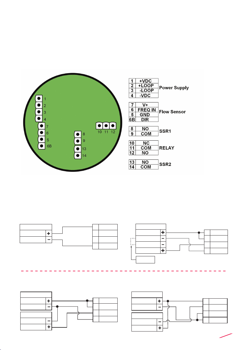
Electrical
• Supply Voltage: 12 to 24 VDC ± 10% regulated
• FLS hall effect ow Sensor power:
- 5 VDC @ < 20 mA
- Optically isolated from current loop
- Short circuit protected
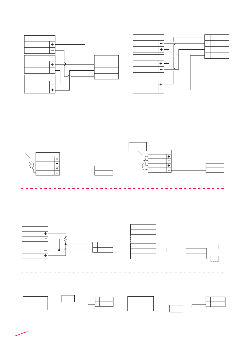
• 1 x Current output:
- 4-20 mA, isolated, fully adjustable and reversible
- Max loop impedance: 800 Ω @ 24 VDC - 250 Ω @
12 VDC
• 2 x Solid State Relay output:
- User selectable as MIN alarm, MAX alarm, Pulse Out, Window alarm, Off
- Optically isolated, 50 mA MAX sink, 24 VDC MAX pull-up voltage
- Max pulse/min: 300
- Hysteresis: User selectable
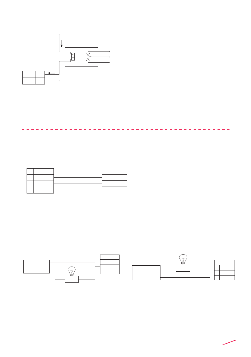
• 1 x Relay output:
- User selectable as MIN alarm, MAX alarm, Pulse
Out, Window alarm, Off
- Mechanical SPDT contact
- Expected mechanical life (min. operations): 107
- Expected electrical life (min. operations): 105N.O./N.C. switching capacity
5A/240VAC
- Max pulse/min: 60
- Hysteresis: User selectable
Environmental
• Operating temperature: -20 to +70°C (-4 to 158°F)
• Storage temperature: -30 to +80°C (-22 to 176°F)
• Relative humidity: 0 to 95% not condensing
Standards & Approvals
• Manufactured under ISO 9001
• Manufactured under ISO 14001
• CE
• RoHS Compliant
• GOST R