Fire-Lite Alarms I300-6 User manual

1 I56-4097-000
BEFORE INSTALLING
If the modules will be installed in an existing operational system, inform the
operator and local authority that the system will be temporarily out of service.
Disconnect the power to the control panel before installing the modules. This
system contains static sensitive components. Always ground yourself with a
proper wrist strap before handling any circuits so that static charges are re-
moved from the body. The housing cabinet should be metallic and suitably
grounded.
NOTICE: This manual should be left with the owner/user of this equipment.
GENERAL DESCRIPTION
The I300-6 Six Fault Isolator Module provides six equivalent circuits that will
allow a portion of the communications loop to continue operating when a
short circuit occurs on that loop. An amber LED indicator will blink in the
noromal state for each of the six inputs and will latch on during a short circuit
condition. The module will automatically restore the communications loop to
normal condition when the short circuit is removed.
CONTENTS INCLUDE:
(6) 1 × 4 Terminal Blocks
(2) 1¼˝ (32mm) Stand offs
(4) Machine Screws
(2) Nuts
COMPATIBILITY REQUIREMENTS
To ensure proper operation, this module shall be connected to a compatible
FireLite system control panel.
COMPONENTS
Following are descriptions of the I300-6 mounting frameworks. There are two
mounting options for I300-6 modules:
• Up to six I300-6 modules can be installed on a CHS-6 in a CAB-3, CAB-4
or BB-25 cabinet
• One or two I300-6 modules can be installed in a BB-XP cabinet
Chassis
The CHS-6 chassis is used to mount I300-6 modules in a BB-25, CAB-3 or
CAB-4 Series cabinet. It accommodates up to six I300-6 modules in a single
cabinet row three modules wide and two modules deep.
I300-6 Six Fault Isolator Module
SPECIFICATIONS
Normal Operating Voltage: 15-32VDC
Stand-By Current: 2.7 mA
Maximum Current Draw: 102 mA
Temperature Range: 32°F to 120°F (0°C to 49°C)
Humidity: 10 to 93% Non-condensing
Dimensions: 6.8˝H × 5.8˝W × 1.0˝D
Accessories: CHS-6 Chassis; BB-25 Cabinet; BB-XP Cabinet; CAB-3 Series Cabinets; CAB-4 Series Cabinets
Wire Gauge: 12-18 AWG
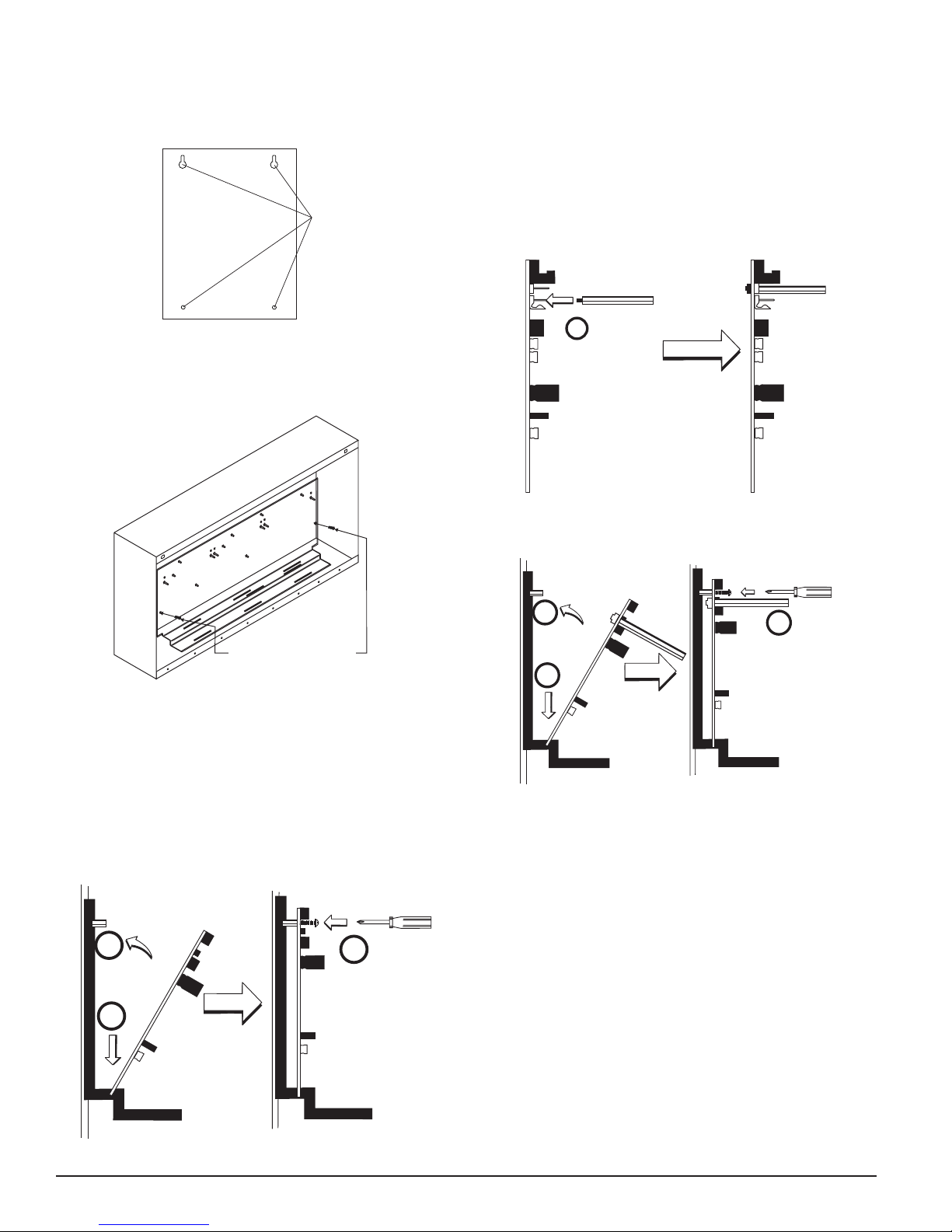
FIGURE 1. CHS-6 CHASSIS:
MOUNT WITH
SELF-THREADING SCREWS
TO BACK OF CABINET
The BB-XP cabinet has a built-in chassis that will accommodate one or two
I300-6 modules.
FIGURE 2. BB-XP CABINET:
The front I300-6 module positions of each chassis are offset below the rear
I300-6 module positions so that all of the status indicators are visible.
Cabinets
A BB-25, CAB-3 or CAB-4 Series cabinet will house the CHS-6 chassis with up
to six I300-6 modules installed on it. Refer to cabinet installation documents
for dimensions.
The BB-XP cabinet houses one or two I300-6 modules on the internal chassis
that is part of the cabinet. Refer to cabinet installation documents for dimen-
sions.
I56-4097-000
INSTALLATION AND MAINTENANCE INSTRUCTIONS
C0236-01
C0234-06
One FireLite Place
Northford, CT 06472
Phone: 203.484.7161

Step 1: Insert the bottom of the I300-6 module down into a rear slot on the
chassis.
Step 2: Carefully pivot the upper edge of the board back towards the back of
the chassis until it touches the two standoffs.
Step 3: Align two 4-40 screws with the two standoffs and tighten.
Step 4: Wire the modules according to the instructions in this manual.
The steps in Figures 6A – 6C describe and illustrate module installation when
the rear chassis position and the position in front of it will be filled. Front
position installation is possible only if the rear position is filled with a module.
FIGURE 6A. INSTALLATION OF I300-6 MODULE IN A REAR CHASSIS
POSITION, METHOD TWO:
1
Step 1: Install two long standoffs in the lower mounting holes using two 4-40
nuts as shown.
FIGURE 6B.
3
2
4
Step 2: Insert the bottom of the I300-6 module down into a rear slot on the
chassis.
Step 3: Carefully pivot the upper edge of the board back towards the back of
the chassis until it touches the two standoffs on the board.
Step 4: Align two 4-40 screws with the two standoffs on the chassis and
tighten.
Step 5: Wire the modules according to the instructions in this manual.
FIGURE 6C. INSTALLATION OF I300-6 MODULE IN FRONT CHASSIS
INSTALLATION STEPS
1. Cabinet Mounting
In a clean, dry area, mount the backbox using the four holes provided in the
back surface of the cabinet.
FIGURE 3. TYPICAL MOUNTING HOLE LOCATIONS:
BACKBOX
MOUNTING
HOLES
2. Chassis Installation
The CHS-6 chassis is mounted in the BB-25, CAB-3 or CAB-4 Series cabinets. It
is shipped with two self-threading screws, which are used to fasten the chassis
to the back wall of the cabinet (see Figure 4).
FIGURE 4: MOUNTING THE CHS-6 CHASSIS
MOUNT WITH
SELF-THREADING SCREWS
TO BACK OF CABINET
The BB-XP cabinet comes with the chassis already installed, so no mounting
is necessary.
3. Module Installation
There are two methods for installing a module in the rear position of a chas-
sis. Method one is for installation of a rear module only, when no module will
be installed in front of it. Refer to Figure 5 for instructions. Method two is for
installation of a rear module when another module will be installed in the
chassis position in front of it. Refer to Figures 6a and 6b for method two. All
necessary screws and standoffs are supplied with the modules.
FIGURE 5. INSTALLATION OF REAR MODULE ONLY, METHOD ONE:
2
1
3
2 I56-4097-000
C0236-00
C0235-00
C0249-00
C0249-01
C0226-01
C0225-01

3 I56-4097-000
POSITION:
2
3
1
Step 1: Insert the bottom edge of the I300-6 module down into a front slot of
the chassis.
Step 2: Carefully pivot the upper edge of the board towards the back of the
chassis until it touches the 1¼˝ (31.75mm) standoffs installed on the
rear module.
Step 3: Align two 4-40 screws with the two standoffs and tighten.
Step 4: Wire the modules according to the instructions in this manual.
PROGRAMMING
The I300-6 module operates with the following Fire Alarm Control Panels:
• MS-9050UD
• MS-9200UDLS
• MS-9600LS
• MS-9600UDLS
6.8"
5.8"
FROM PANEL
OR PREVIOUS DEVICE
SIGNAL LINE CIRCUIT
32 VDC MAX.
TWISTED PAIR
IS RECOMMENDED
TO NEXT
DEVICE
–+
–
+
–
+
STAT US
INDICATORS
FIGURE 7. WIRING AND PROGRAMMING THE I300-6 MODULE:
C0205-05
WIRING
1. Install module wiring in accordance with the job drawings and appro-
priate wiring diagrams.
2. Make electrical connections by stripping approximately 1/4˝ (6.35mm)
of insulation from the end of the wire sliding the bare end of the wire
under the clamping plate, and tightening the clamping plate screw.

4 I56-4097-000
©2014 Fire•Lite Alarms, Inc.
FCC STATEMENT
This device complies with part 15 of the FCC Rules. Operation is subject to the following two conditions: (1) This device may not cause harmful interference, and (2) this device must
accept any interference received, including interference that may cause undesired operation.
NOTE: This equipment has been tested and found to comply with the limits for a Class B digital device, pursuant to Part 15 of the FCC Rules. These limits are designed to provide
reasonable protection against harmful interference in a residential installation. This equipment generates, uses and can radiate radio frequency energy and, if not installed and used
in accordance with the instructions, may cause harmful interference to radio communications. However, there is no guarantee that interference will not occur in a particular instal-
lation. If this equipment does cause harmful interference to radio or television reception, which can be determined by turning the equipment off and on, the user is encouraged to
try to correct the interference by one or more of the following measures:
– Reorient or relocate the receiving antenna.
– Increase the separation between the equipment and receiver.
– Connect the equipment into an outlet on a circuit different from that to which the receiver is connected.
– Consult the dealer or an experienced radio/TV technician for help.
Other Fire-Lite Alarms Control Unit manuals
Popular Control Unit manuals by other brands

Firmtech
Firmtech FBL770BC quick guide

Viessmann
Viessmann VITOTRONIC 300-K operating instructions

IFM Electronic
IFM Electronic ecomat 100 CR2010 Device manual

ProMinent
ProMinent DHV-UR Assembly and operating instructions

Siemens
Siemens SIM-16RC installation instructions

heat-timer
heat-timer ETV Platinum Plus Installation and operation manual