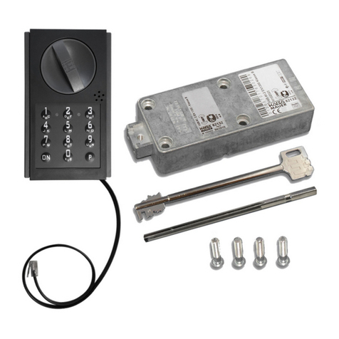
Kaba Mauer 82132 User manual

Revision level 15.02.2016
Page 1 of 19
Mounting Instructions 82132/33 Code-Combi B with Aluminium Control Unit
1 General
These mounting instructions are the basis for the approval by ECBS, VdS, A2P (CNPP)- DNV, UL. Installation of the
lock to be performed exclusively in accordance with these instructions.
Guidelines of the national certification bodies are to be considered and complied with in addition.
Use high quality alkaline/manganese monobloc batteries only. Low quality batteries may cause oxidation which results in a
functional failure of the lock..
Avoid residual crystalline moisture in the cabinet (e.g. from varnishing) to make sure that electrical contact areas are not
attacked.
Make sure that the ingress of dirt or detergents (e.g. remaining fillers or cold cleaners) is prevented.
Do not grease/oil the lock or key.
It is recommended, that unauthorized persons have no access to security sensitive parts of the lock, also the door of the
safe, where the lock is installed, is open.
2 Mounting instructions for lock and control unit
-RH version (standard version):
Lock mounting position
Bolt LH, keyhole horizontal
Bolt downwards, keyhole vertical
Bolt upwards, keyhole vertical
-LH version
Lock mounting position
Bolt RH, keyhole horizontal
Any variation of the lock or key may result in functional trouble and must better not be done. All claims under guarantee and
warranty will expire in this case.
Lock fastening: Use of M6 steel socket head cap screws or BSW ¼" steel bolts. The length of engagement must
correspond to the applicable standards considering the thickness of the lock of 30 mm and the screwing height of the lock
case of 24 mm.
Fastening screws: minimum property class 4.8 and maximum property class 8.8.
Screws to be secured either by lock washer, flat spring, tooth lock washer, fan type lock washer considering the diameter
(d1) or to be cemented.
Screw tightening moment : minimum 5 Nm and maximum 6 Nm.
The bolt must be floating in installed condition.
Perfect function of the lock and of any additional connected or triggered systems (e.g. boltworks) must be warranted and
checked by specialists during installation of the lock.
The lock must be mounted in closed condition (bolt extended).

Revision level 15.02.2016
Page 2 of 19
Mounting Instructions 82132/33 Code-Combi B with Aluminium Control Unit
The opening (cable gland) in the door of the secure storage unit may not be greater than 100 sq mm (see mounting
diagrams on Page 5 and following).
The lock is designed for installation in secure storage units made of steel. Installation in storage units consisting of other
material e.g. plastic is not allowed.
Do not apply any kind of force (e.g. hammer blows) for screw fitting and adjustment of the lock.
Lock to be installed covered and so as to prevent opening by boring.
The two way key must be insertable without jamming.
Use of the Kaba-Mauer key guide (see Fig. 1) is recommended. Considering DIN 2768-mH, the keyhole in the door of the
secure storage unit should be dimensioned accordingly (see Fig. 1).
Fig. 1: Key guide 86101
In cases where the Kaba-Mauer key guide or key carrier guide are not used, the maximum cross sectional area of the
keyhole in the door of the secure storage unit and/or the lock armour plating may not exceed the dimensions given in Fig. 2
considering DIN 2768-mH. All dimensions deviating from these specifications are to be coordinated separately with the
certification bodies (test houses).
Fig. 2 : Max. cross sectional area of keyhole
For installation and adjustment of the lock on the door, make sure that the key can be inserted into the lock without applying
force and without jamming. This can be achieved by mounting the lock according to the following pattern of mounting holes
(Fig. 3). For further lock dimensions please refer to the Kaba Mauer Catalogue Sheet.
Fig. 3: Fastening hole pattern
Code-Combi B
X (mm)
Y (mm)
71161
17
12.5
R4
R4
O8
4,2
4,2
5,9
5,9
25,5 12,75
41
49 66,7
7,5max.
O1
2
m
ax.
max.X max.Y

Revision level 15.02.2016
Page 3 of 19
Mounting Instructions 82132/33 Code-Combi B with Aluminium Control Unit
Technical data:
Lift height of bolt 12 mm
Bolt extension in locked-out condition: approx. 14 mm
Bolt width: 25,4 mm; Bolt height: 15 mm
The maximum allowable force acting on the key bolt in opposite direction to the direction of locking, the maximum locking
force and the lateral load acting on the bolt, correspond to 1 KN and should not exceed this value. Provision should be made
design wise for bolt stoppers on both ends or for a bolt support.
The bolt was according to EN1300 with a permanent load of 2,5 N over 10.000 cycles tested. These load should not be
exceeded permanently.
The actuating torque on the key / the spindle must not exceed 2.5 Nm.
Fastening of the boltwork: via two M4 threads on the front end of the bolt head.
3 Assembly
Adjust and fix lock using the fastening screws.
Stick on self stick rubber buffers on the safe door (see fig. 5). The dimensions and the position you will find in assembly
drawings in chapter 6. All traces of grease on adhesion surface to be removed carefully before!
Notice: The rubber buffer must be used correctly, otherwise you loose the VdS conformity!
Fig. 5: stick on rubber buffers
43
50 77,5
27
70
Fig. 5: mounting steps

Revision level 15.02.2016
Page 4 of 19
Mounting Instructions 82132/33 Code-Combi B with Aluminium Control Unit
Insert actuating spindle as far as it will go with the bored end ahead (locking function warranted only this way).
Cutting to size of the actuating spindle (before assembly): the required length results from the "clearance between
mounting plane of lock to mounting plane of control unit" + "40 mm (tolerance –0.5 mm). Cutting to size on the end
without bore only!
Fig. 6:
Spindle retention element to be slip-fitted on actuating spindle as shown by Fig. 6.
Align headless screw and lower bore on control unit for inserting Allan key.
This requirement must be considered correspondingly for all the other mounting positions also.
Fig. 7:
Connecting cable of the control unit to be routed through the door to the lock.
Make sure that connecting cable is not damaged during installation. Cable sheathing or flexible leads must not be
impaired, otherwise hazard of a short circuit. Protect the cable by protective hoses or plastic pipes in the area of
transition and moving parts. Make sure also that the cable is not buckled or installed in pinched condition.
Align aluminium control unit and fix by 3 or 4 screws according to version of control unit involved.
Cable penetrations must be deburred. See assembly drawing for cable penetrations and borehole dimensions .
Make sure that spindle retention can be rotated smoothly between control unit and surface of door. Re-work door surface
as necessary.
Snap-on actuating knob.
The guide pin on the knob (A) must engage in the sickle-shaped recess (B) of the control unit.
Position for bar dolly : Bar horizontal, lock horizontal
Bar vertical, lock vertical
Fig. 8:
(B)
(A)
22 X

Revision level 15.02.2016
Page 5 of 19
Mounting Instructions 82132/33 Code-Combi B with Aluminium Control Unit
Tighten headless
screws
Fasten spindle and knob by means of an Allan key 2.0 mm.
Adjustment of the assembly is correct once the bar dolly after slight clockwise turning jumps back by resilience to its
horizontal home position.
Fig. 9:
Join and fasten battery compartment. See assembly drawing (version with external battery compartment) for dimensions of
penetrations).
For cabling plug connecting plugs according to instructions of the following table:
Marking on lock case
Connection for
Marked "input unit“
6 pole connecting cable to the electronic input
system
Marked "power“
4 pole operating voltage (battery case)
Confusion of the connecting cables does not produce any damage of the electronic system of the lock. The lock will not be
operable in this case and must be connected correctly in accordance with the circuit diagram.
Always press the latching clip of the plug against the plug housing for disconnecting plugs and sockets. Do not pull out
plug reaching for the plug housing or the cable.

Revision level 15.02.2016
Page 6 of 19
Mounting Instructions 82132/33 Code-Combi B with Aluminium Control Unit
4 Crimping of the 4-pole battery connector (version with battery compartment integrated in the
door armature Optioncode IBF)
Route cable through provided feed-through opening:
Plug for keypad is factory crimped
Plug for battery (marked "Bat") must be insulated and
crimped after feeding through the door
Lateral view: Plug-in position
Top view: Plug-in position
Insert flexibles into grooves as far as they will go and crimp
according to crimping tool instructions (as indicated by the
manufacturer):
4 yellow
3 green
2 brown
1 white
If a 6-pole connector is used, the pins 5 and 6 beside the yellow line (4) will stay empty. As pin 1 remains the white line.
white flexible
Plug contact end

Revision level 15.02.2016
Page 7 of 19
Mounting Instructions 82132/33 Code-Combi B with Aluminium Control Unit
5 Crimping of the 6-pole battery connector (version with battery compartment integrated in the
door armature)
Route cable through provided feed-through opening:
Plug for keypad is factory crimped
Plug for battery (marked "Bat") must be insulated and
crimped after feeding through the door
Lateral view: Plug-in position
Top view: Plug-in position
Insert flexibles into grooves as far as they will go and crimp
according to crimping tool instructions (as indicated by the
manufacturer)
If a 4-pole connector is used the line 5 (brown) and 6 (white) beside the green line (4) will stay outside the connector and are not
used. As pin 1 remains the pink line!
pink flexible
Plug: contact end

Revision level 15.02.2016
Page 8 of 19
Mounting Instructions 82132/33 Code-Combi B with Aluminium Control Unit
6 Final check
Bei in den Beschlag integriertem Batteriefach (option code IBF) wird durch das Einlegen der Batterie der
Batteriewechselkontakt aktiviert. Every time the lock is opened a constant acoustic signal will be heard accompanied by
alternate red/green flashing LED. It is imperative to have these signals cancelled.
Cancellation of signals
1)
Press ON
2)
Press P
3)
Enter valid primary code
3)
Press P
5)
Press 9
Function of the lock to be checked according to operating instructions. Also check mechanical opening by the two-way key.
Make sure when opening the lock that the bar dolly can be moved smoothly.

Revision level 15.02.2016
Page 9 of 19
Mounting Instructions 82132/33 Code-Combi B with Aluminium Control Unit
7 Mounting drawings
7.1 82132/33 Code-Combi B with aluminium control unit (option codes BAS, TOU, BSW)
Lock mounting position
Control unit mounting position
Door penetrations
Keyhole (in lock)
Battery compartment separate
43
24,5
34,5
O3,2
3,2O
Depth of battery compartment approx. 60 mm
911,3
6,1
3,2
6,1
Adhesive rubber
buffer (self stick)
Cable gland
⍁10 mm or Ø 11,25 ±0,05 mm
82132/33 Code-Combi B mit
Aluminiumbedieneinheit
40
58,5
30
17
20
135,5

Revision level 15.02.2016
Page 10 of 19
Mounting Instructions 82132/33 Code-Combi B with Aluminium Control Unit
7.2 82132/33 Code-Combi B with aluminium control unit (option codes BAS, TRL, BSW)
Lock mounting position
Control unit mounting position
Door penetrations
Keyhole (in lock)
Battery compartment separate
3,2
6,1
11,3 9
6,1
Cable glands
⍁10 mm or
Ø 11,25 ±0,05 mm
Adhesive buffer
(self stick)
135,5
40
21
17
21
30
53
Depth of battery compartment approx. 60 mm
43
24,5
34,5
O3,2
3,2O

Revision level 15.02.2016
Page 11 of 19
Mounting Instructions 82132/33 Code-Combi B with Aluminium Control Unit
7.3 82132/33 Code-Combi B with aluminium control unit (option codes BAS, TUO, BSW)
Lock mounting position
Control unit mounting position
Door penetrations
Keyhole (in lock)
Battery compartment separate
Depth of battery compartment approx. 60 mm
43
24,5
34,5
O3,2
3,2O
Cable gland
⍁10 mm or
Ø 11,25 ±0,05 mm
Adhesive buffer
(self stick)
40
30
21
53
17
135,5
70
67
38
60,5
37
6,1
3,2
911,3
6,1

Revision level 15.02.2016
Page 12 of 19
Mounting Instructions 82132/33 Code-Combi B with Aluminium Control Unit
7.4 82132/33 Code-Combi B with aluminium control unit (option codes BAS, TLR, BSW)
Lock mounting position
Control unit mounting position
Door penetrations
Keyhole (in lock)
Battery compartment separate
Depth of battery compartment approx. 60 mm
43
24,5
34,5
O3,2
3,2O
6,1
3,2
11,39
6,1
Cable gland
⍁10 mm or Ø 11,25 ±
6,1
3,2
911,3
6,1
0,05 mm
Adhesive buffer
(self stick)
135,5
40
17
21
53
30

Revision level 15.02.2016
Page 13 of 19
Mounting Instructions 82132/33 Code-Combi B with Aluminium Control Unit
7.5 82132/33 Code-Combi B with aluminium control unit (option codes BAS, TRS, BSS, bolt downwards)
Lock mounting position
Control unit mounting position
Door penetrations
Keyhole (in lock)
Battery compartment separate
911,3
6,1
3,2
6,1
Depth of battery compartment approx. 60 mm
43
24,5
34,5
O3,2
3,2O
Cable gland
⍁10 mm or Ø 11,25 ±0,05 mm
Adhesive buffer
(self stick)
53
30
17
21
135,5
40

Revision level 15.02.2016
Page 14 of 19
Mounting Instructions 82132/33 Code-Combi B with Aluminium Control Unit
7.6 82132/33 Code-Combi B with aluminium control unit (option codes BAS, TRS, BSS, bolt upwards)
Lock mounting position
Control unit mounting position
Door penetrations
Keyhole (in lock)
Battery compartment separate
6,1
3,2
911,3
6,1
Cable gland
⍁10 mm or Ø 11,25 ±0,05 mm
Adhesive buffer
(self stick)
53
30
17
21
135,5
40
Depth of battery compartment approx. 60 mm
43
24,5
34,5
O3,2
3,2O

Revision level 15.02.2016
Page 15 of 19
Mounting Instructions 82132/33 Code-Combi B with Aluminium Control Unit
7.7 82132/33 Code-Combi B with aluminium control unit (option codes BAS, TLS, BSS, bolt downwards)
Lock mounting position
Control unit mounting position
Door penetrations
Keyhole (in locky )
Battery compartment separate
Depth of battery compartment approx. 60 mm
43
24,5
34,5
O3,2
3,2O
Cable gland
⍁10 mm or Ø 11,25 ±0,05 mm
Adhesive buffer (self stick)
135,5
21
58
25
30
40
911,3
6,1
3,2
6,1

Revision level 15.02.2016
Page 16 of 19
Mounting Instructions 82132/33 Code-Combi B with Aluminium Control Unit
7.8 82132/33 Code-Combi B with aluminium control unit (option codes BAS, TLS, BSS, bolt upwards)
Lock mounting position
Control unit mounting position
Door penetrations
Keyhole (in lock)
Battery compartment separate
Depth of battery compartment approx. 60 mm
43
24,5
34,5
O3,2
3,2O
135,5
21
58
25
30
R
4
40
Adhesive buffer (self stick)
Cable gland
⍁10 mm or Ø 11,25 ±0,05 mm
6,1
3,2
911,3
6,1

Revision level 15.02.2016
Page 17 of 19
Mounting Instructions 82132/33 Code-Combi B with Aluminium Control Unit
7.9 82132/33 Code-Combi B with aluminium control unit (option codes BAK, TRL)
Lock mounting position
Control unit mounting position
Door penetrations
Keyhole (in lock)
Battery compartment separate
3,2
6,1
11,3 9
6,1
Depth of battery compartment approx. 60 mm
43
24,5
34,5
O3,2
3,2O
100
60
21
17
40
30
53
O18
135,5
Adhesive buffer
(self stick)
Cable gland
⍁10 mm or Ø 11,25 ±0,05 mm

Revision level 15.02.2016
Page 18 of 19
Mounting Instructions 82132/33 Code-Combi B with Aluminium Control Unit
7.10 82132/33 Code-Combi B with aluminium control unit (option codes BAH, TOU, BSW)
Lock mounting position
Control unit mounting position
Door penetrations
Keyhole (in lock)
Battery compartment separate
Depth of battery compartment approx. 60 mm
43
24,5
34,5
O3,2
3,2O
911,3
6,1
3,2
6,1
60
100 40
58,5 20
30
17
O18 135,5
Cable gland
⍁10 mm or Ø 11,25 ±0,05 mm
Adhesive buffer (self
stick)

Revision level 15.02.2016
Page 19 of 19
Mounting Instructions 82132/33 Code-Combi B with Aluminium Control Unit
7.11 82132/33 Code-Combi B with aluminium control unit
Unter dem Punkt 6 Montageskizzen (Seite 6 bis 15) ist das Kabeldurchführungsloch (max. 100 mm²) zeichnerisch idealerweise
positioniert. Abweichend davon wird es den Schrank-, Tresor und Anlagenbauern ermöglicht, das Kabeldurchführungsloch
(siehe unten Abb. 9 bis 14) auch innerhalb der grau gezeichneten Fläche zu positionieren und zu fertigen.
Hinweis:
Es darf die Kabelzugentlastung der Bedieneinheit (Tastatur) nicht zerstört werden.
Die Mikroschalterfunktion (Schaltbereich des Mikroschalter) darf durch die Kabelverlegung nicht beeinträchtigt werden und
muss bleibend sichergestellt sein.
Schloss waagerecht / Beschlag waagerecht (Optionscodes BAS TRW + TLW)
Abb. 10 Abb. 11
Schloss senkrecht / Beschlag waagerecht (Optionscodes BAS TRS + TLS)
Abb. 12 Abb. 13
Schloss senkrecht / Beschlag senkrecht (Optionscodes BAS TOS + TUS)
Abb. 13 Abb. 14
70
77,5 50
27
43
5077,5
27
43
70
5077,5
27
43
70
25
43
70
50 65,5
70
77,5
50
27
43
text
Other manuals for 82132
2
This manual suits for next models
1
Table of contents
Other Kaba Mauer Control Unit manuals