manuals.online logo
Brands
  1. Home
  2. •
  3. Brands
  4. •
  5. Fire-Lite
  6. •
  7. Fire Alarm
  8. •
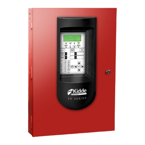
  9. Fire-Lite MS-9200(C/E) User manual

Fire-Lite MS-9200(C/E) User manual

DF-51276  Page 1 of 4
GENERAL
The MS-9200 is a compact, cost-effective, addressable
fire alarm control panel with a capacity of 198 FireLite
300 Series devices. A single Signaling Line Circuit (SLC)
loop supports up to 99 smoke detectors and 99 control or
monitor modules. The panel uses surface-mount technol-
ogy and is designed for ease of installation and program-
ming. It features the latest in fire protection technology,
including maintenance alert and automatic detector test.
FEATURES
 SLC supports up to 198 addressable devices (99 detec-
tors and 99 monitor or control modules).
 SLC can be configured for Style 4, 6, or 7 operation.
 Dual Integral Notification Appliance (bell, signal) Circuits
(NAC's), Style Y or Z (Class B or A).
 3.0 Amp Notification Appliance (bell, signal) power, ex-
pandable to 6.0 Amperes.
 NAC's may be programmed for Steady, March Time,
Temporal or California Code(requires software P/N 73750
or greater).
 Alarm, trouble and supervisory relays, standard.
 Maintenance alert warns when smoke detector dust ac-
cumulation is excessive.
 Optional UDACT-F Digital Alarm Communicator reports
56 zones or 198 points to a Central Station.
 Optional LCD-40 Series alphanumeric, 40-character,
backlit remote serial annunciators operate over high-
speed EIA-485 port. Up to 32 may be supported by MS-
9200 (requires software P/N 73750 or greater).
 Optional printer interface  UL listed for permanent
attachment.
 Integral 40-character LCD display with backlighting.
 Keypad programmable on panel, with two user-defined
passwords, plus an Autoprogram feature.
 Custom English labels per point may be manually en-
tered or selected from an internal library file.
 Autoprogram and Walk Test features identify 2 or more
devices set to same address.
 Real-time clock/calendar.
 History file with 500-event capacity.
 Waterflow or supervisory selection per monitor point.
 System alarm verification, smoke only.
 Presignal delay option per NFPA 72.
 Silence Inhibit and Auto Silence timer options.
 Battery charger for up to 60 hours of standby power.
 Fuseless, power-limited technology meets new UL power-
limiting requirements, effective May 1, 1995.
 Rapid poll algorithm for manual stations. Responds to
alarm/activation in less than two seconds.
 Operates with untwisted, unshielded wire (up to 1,000
feet) for retrofit applications (U.S. Patent 5,210,523).
 300 Series addressable devices feature decimal address
selection. Address of each device can be easily set in the
field by use of a screwdriver. Smoke detectors also
feature a plug-in wiring connector for ease of installation
and serviceability.
 Remote Acknowledge/Silence/Reset/Drill via M300 mod-
ules.
 SLC loop maximum length 10,000 ft. @ 12 AWG (3.25
mm2).
S624
(MS-9200, MS-9200E)
CS68
(MS-9200C)
0X9A3.AY
(MS-9200, CP300,
SD300, BG-10LX,
M300, M301, M302,
C304, I300)
(Requires DP-9200)
0Y6A3.AY (SD300T)
MEA
16-94-E
(MS-9200 & M302)
3-94-E
(M300, M301,
I300,
SD300, CP300)
326-94-E
(SD300T, C304)
7165-0075:158
(MS-9200)
7300-0075:159
(M300, M301, I300, C304)
7300-0075:162
(M302)
7272-0075:172
(SD300, SD300T)
MS-9200
SYSTEM ALL NORMAL
10:12 A MON 01/15/96
MS-9200(C/E)
Addressable
Fire Alarm Control Panel
A1-100
March 23, 1998
Section: Addressable
ISO-9001
Engineering and Manufacturing
Quality System Certified to
International Standard ISO-9001 Made in the U.S.A.
This document is not intended to be used for installation purposes. We try to keep our
product information up-to-date and accurate. We cannot cover all specific applications or
anticipate all requirements. All specifications are subject to change without notice. For
more information, contact FireLite. Phone: (203) 484-7161 FAX: (203) 484-7118
12 Clintonville Road, Northford, Connecticut 06472
Page 2 of 4  DF-51276
SYSTEM PERIPHERALS
SLC Loop (2 wires) supports 198 devices (99 Detectors/99 Modules)
EIA-485 (2 wires)
EIA-485
(4 wires)
24 VDC
24 VDC
SD300(A)
Photoelectric
smoke detector
CP300(A)
Ionization
smoke detector
SD300T(A)
Photoelectric
smoke detector
with thermal
sensor
BG-10LX M302(A) M300(A) C304(A)
M301(A)
Supervised loop of
compatible 2-wire
smoke detectors Supervised Initiating
Device Circuit
(normally open
contact type)
Supervised
Notification
Appliance
Circuit or
Form C Relay
LCD-40
Alphanumeric Annunciator
LCD-40L
Alphanumeric Annunciator
LDM-32F
Graphic Annunciator
up to 56 zones or 198 points
AFM Series Annunciators
UDACT-F
D.A.C.T. can be installed
within MS-9200 or
remotely in ABS-8RF or
UBS-1F remote backbox
Miniature
version
of M300
Optional
Reverse
Polarity/
City Box
Output
(order
RTM-8F)
Notification Appliance
(bell, signal) Circuits (NAC's)
Optional EIA-232 interface module
for PC computer or diagnostic
printer (PIM-24 required, see Notes.)
MS-9200(C)
8 Optional Form-C
5 Amp Relays (order RTM-8F)
Requires DIM-485 Interface Module (see Notes).
24 VDC
24 VDC
NAC Power
24 VDC
Notes: 1) A suffix should be included when ordering Canadian
version 300 Series devices.
2) C suffix designates Canadian version MS-9200.
3) LCD-40 and printer option cannot be used simultaneously.
EIA-232
(3 wires)
DF-51276  Page 3 of 4
COMPATIBLE ADDRESSABLE DEVICES
SD300(A) Addressable Photoelectric Smoke Detec-
tor. Includes mounting plate and plug-in
wiring terminal block.
SD300T(A) Same as SD300, plus a 135°F thermostat
heat detector.
CP300(A) Addressable Ionization Smoke Detector.
BG-10LX(A) Addressable Manual Station based on the
popular FireLite BG-10L dual-action
station.
M300(A) Addressable Monitor Module for one zone
of normally open dry contact initiating
devices. Mounts in standard 4" box.
Includes plastic cover plate and end-of-
line resistor. Features polling/alarm LED
and decimal address switches. May be
configured for either Style B (Class B) or
Style D (Class A) operation.
M301(A) Miniature version of M300. Excludes LED
and Style D option. Connects with wire
pigtails. May mount in device backbox.
M302(A) Similar to M300, but may monitor up to 20
conventional 2-wire detectors. Requires
external 24 VDC power. (Consult factory
for compatible smoke detectors.)
C304(A) Addressable Control Module for one Style
Y/Z (Class B/A) zone of supervised
polarized Notification Appliances, or may
be configured as a dry contact (Form-C)
relay rated at 2 amps. Mounts in standard
4" box. Features polling LED and decimal
address switches. Notification Appliance
Circuit option requires external 24 VDC
power. (Consult factory for compatible
Notification Appliances.)
I300(A) This module isolates the SLC loop from
short circuit conditions (required for Style 7
operation).
NOTES: 1) A suffix should be included only when order-
ing ULC listed units (e.g. SD300A, M300A). 2) For more
detailed information on Compatible Addressable Devices
for use with the MS-9200, please see the following data
sheets (document numbers): SD300/SD300T (DF-51320),
CP300 (DF-51311), MS-9200 Addressable Modules (DF-
51339), and BG-10LX (DF-51366).
COMPATIBLE ANNUNCIATORS
LCD-40 Series: 40-character, backlit LCD-type fire an-
nunciators capable of displaying English-language text
(requires one DIM-485 per MS-9200 panel to interface
with up to 32 LCD-40 annunciators).
AFM/AFM-X Series: LED-type fire annunciators ca-
pable of providing up to 56 software zones of annuncia-
tion. Available in increments of 16 or 32 with expandable
(AFM-X Series) and non-expandable (AFM Series) con-
figurations to meet a variety of applications.
LDM Series: Lamp Driver Module series for use with
custom graphic annunciators.
NOTE: For more detailed information on Compatible
Annunciators for use with the MS-9200, please see the
following data sheets (document numbers): LCD-40 (DF-
51474), AFM/AFM-X (DF-51465), and LDM Series (DF-
51384).
FIELD-PROGRAMMING FEATURES
Off-Line Programming: Create entire program in your
office using a Windows®-based PC computer (order pro-
gramming kit PK-9200W separately). Upload/Download
system programming locally to the MS-9200 in less than
one minute.
Auto-Programming: Command the MS-9200 to pro-
gram itself (takes less than 30 seconds). In the Auto-
Program mode, the MS-9200 scans for all possible de-
vices at all addresses, stores the device types, and ad-
dresses found, and then loads default values for all op-
tions (General Alarm). It also checks for two or more
devices set to the same address.
On-Line Edit: While still providing fire protection, the
MS-9200 may be programmed from the front panel. Sim-
ple menu trees displayed on the LCD allow the trained
user to perform all functions without referring back to the
programming manual.
English Label Library: Quickly select labels from a
standard library of more than 50 adjectives/nouns, such
as FLR 3 HALLWAY, or enter custom labels letter-by-
letter. Use recall function to repeat previously used label.
Program Check: Automatically catch common errors,
such as relays not linked to any zone or point.
MAINTENANCE ALERT
The MS-9200 continually monitors each smoke detector
and responds to a reading of 80% of the detectors alarm
threshold. If the detector continually reports an 80% thresh-
old reading (8/10 of what is required to be an alarm condi-
tion) for 24 hours, a trouble condition is created. This
reduces the risk of false alarms due to dust and dirt by
alerting a trouble (maintenance) condition rather than initi-
ating a false alarm.
AUTOMATIC TEST OPERATION
The MS-9200 performs an automatic test of each detector
every 2 hours. Failure to meet the test limits causes an
AUTO TEST FAIL trouble type. System Reset clears this
trouble.
NFPA STANDARDS
The MS-9200 complies with the following NFPA 72-1993
Edition, Fire Alarm Systems:
LOCAL (Automatic, Manual, Waterflow, and Sprinkler
Supervisory).
AUXILIARY (Automatic, Manual, and Waterflow) (re-
quires RTM-8F).
REMOTE STATION (Automatic, Manual, and Water-
flow) (requires RTM-8F or UDACT-F).
PROPRIETARY (Automatic, Manual, and Waterflow).
CENTRAL STATION(Automatic, Manual,and Waterflow)
(requires UDACT-F).
SPECIFICATIONS
 Primary input power: 120 VAC, 50/60 Hz, 2.3 Amps.
 Total 24 V system power: 3.6 A (expandable to 6.6 A).
 Standard Notification Circuits: 2 (Style Y or Z).
Page 4 of 4  DF-51276
 Expansion Notification Circuits: up to 99
(using C304 module).
 Notification Appliance Power: 3.0 A (expandable to
6.0A with XRM-24).
 Four-wire detector power: 300 mA.*
 Non-resettable regulated power: 300 mA.*
 Non-regulated power: 2.5 Amps maximum.*
*NOTE: Subtract from total 24 V system power.
 Battery charger range: 7 AH - 17 AH
(BB-17F battery cabinet for 12 - 17 AH batteries).
 Remote charger (panel charger disabled, requires MS-
9200 circuit board #71741, available June 1, 1998):
25-120 AH (use CHG-120F).
 Charge float rate: 27.6 V.
 Charger current limited to 0.8 A.
 Control panel Alarm, Trouble, Supervisory Relay contact
ratings: 2.0 A @ 30 VDC.
CABINET SPECIFICATIONS
Door: 15.218" (38.65 cm) high x 14.718" (37.38 cm) wide
x 0.375" (0.95 cm) deep.
Backbox: 15.0" (38.1 cm) high x 14.5" (36.83 cm) wide x
2.625" (6.67 cm) deep.
Trim Ring: 18.12" (46.02 cm) high x 17.62" (44.75 cm)
wide  16 gauge.
SYSTEM CAPACITY
 Total programmable input/output points: 198
 Addressable Detectors: 99
 Addressable monitor or control modules: 99
 Notification Appliance (Bell) Circuits (NACs) in panel: 2*
 Programmable software zones: 56
 AFM/LDM/LCD-40 Series Annunciators per System: 32
 UDACT-F Digital Alarm Communicator Transmitter: 1
*NOTE: NAC's can be added using C304 control modules.
CONTROLS AND INDICATORS
LED INDICATORS
1. AC POWER (green).
2. FIRE ALARM (red).
3. SUPERVISORY (yellow).
4. ALARM SILENCE (yellow).
5. SYSTEM TROUBLE (yellow).
MEMBRANE SWITCH CONTROLS
1. ACKNOWLEDGE/STEP
2. ALARM SILENCE
3. DRILL
4. SYSTEM RESET (lamp test)
5  16. 12-key pad with full alphabet
17  20. 4 cursor keys
21. ENTER
LCD DISPLAY
40 characters (2 x 20) with long-life LCD display, backlit.
COMPATIBLE ADDRESSABLE DEVICES
See page 3 of this document.
EIA-232 PORT
MODEL DESCRIPTION
PIM-24 Printer/PC Interface Module, Cable, DB9F
Connector and 9-pin male to 25-pin female
adapter.
DIM-485 LCD-40 Display Interface Module.
NOTE: PIM-24 and DIM-485 options are not available
simultaneously.
COMPATIBLE DEVICES, EIA-485 PORT
UDACT-F: Digital Alarm Communicator Transmitter.
LCD-40 Series: 40-character, backlit LCD-type fire an-
nunciators capable of displaying English-language text
(requires one DIM-485 per MS-9200 panel to interface
with up to 32 LCD-40 annunciators).
AFM/AFM-X Series: LED-type fire annunciators ca-
pable of providing up to 56 software zones of annuncia-
tion. Available in increments of 16 or 32 with expandable
(AFM-X Series) and non-expandable (AFM Series) con-
figurations to meet a variety of applications.
LDM Series: Lamp Driver Module series for use with
custom graphic annunciators.
NOTE: For more detailed information on Compatible
EIA-485 Port Devices for use with the MS-9200, please
see the following data sheets (document numbers):
UDACT-F (DF-51294), LCD-40 (DF-51474), AFM/AFM-X
(DF-51465), and LDM Series (DF-51384).
PRODUCT LINE INFORMATION
MODEL DESCRIPTION
MS-9200 Addressable Fire Panel. Includes display,
single printed circuit board, and cabinet.
MS-9200C Same as above with ULC listing and DP-9200
dead-front panel.
RTM-8F Plug-in Relay Transmitter Option Module.
Provides 8 Form-C relays, plus municipal box
& remote station connections.
DP-9200 Full-length internal dead-front panel(required
for FM applications).
UDACT-F Digital Alarm Communicator Transmitter.
XRM-24 120 VAC, 100 VA Transformer. Expands
system power supply. Expands Notification
Appliance power from 3.0 amps to 6.0 amps.
PIM-24 Printer Interface Module required to connect a
40- or 80-column printer.
DIM-485 LCD-40 Display Interface Module required to
convert EIA-232 to EIA-485 for use with the
LCD-40 Series annunciators.
PK-9200W Programming Kit for Windows®-based PC
computer (requires PIM-24 and associated
hardware).
TR-1-R Trim Ring for semi-flush mounting.
BB-17F Battery box, required to mount PS-12120 or
PS-12170 batteries.
BB-55F Battery box, required to house two (2) PS-
12250 batteries and one (1) CHG-120F battery
charger. For batteries greater than 25 AH,
consult factory for housing/mounting arrange-
ments.
CHG-120F Remote battery charging system. Required
for charging 25 to 120 AH batteries (can only
be used in conjunction with MS-9200 circuit
board #71741 available June 1, 1998).
PS-1270 Battery, 12 volt, 7.0 AH, (two required).
PS-12120 Battery, 12 volt, 12.0 AH, (two required).
PS-12170 Battery, 12 volt, 17.0 AH, (two required).
PS-12250 Battery, 12 volt, 25 AH, (two required).
PS-12600 Battery, 12 volt, 60 AH,(two required; requires
CHG-120F).
FCPS-24F Remote Power Supply expands NAC outputs
by 6 Amps or total system power by 4 Amps.
Windows® is a registered trademark of Microsoft Corporation.

Other Fire-Lite Fire Alarm manuals

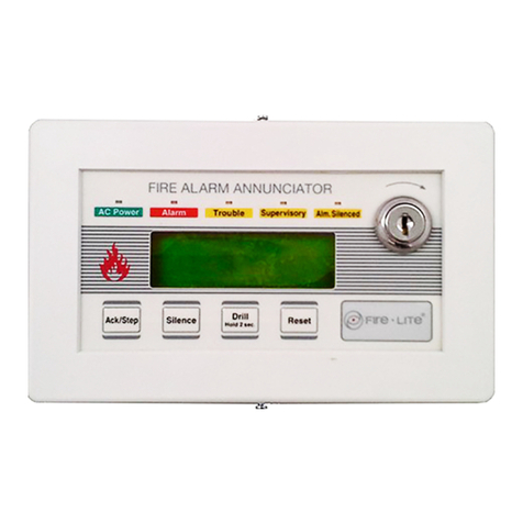
Fire-Lite LCD-80FC User manual

Fire-Lite

Fire-Lite LCD-80FC User manual

Fire-Lite CMP-2401B User manual

Fire-Lite

Fire-Lite CMP-2401B User manual

Fire-Lite CMP-2401B User manual

Fire-Lite

Fire-Lite CMP-2401B User manual

Fire-Lite SENSISCAN 2000 Instruction Manual

Fire-Lite

Fire-Lite SENSISCAN 2000 Instruction Manual

Fire-Lite LED-10 series User manual

Fire-Lite

Fire-Lite LED-10 series User manual

Fire-Lite 411 User manual

Fire-Lite

Fire-Lite 411 User manual

Fire-Lite 300 Series User manual

Fire-Lite

Fire-Lite 300 Series User manual

Fire-Lite BG-12LX User manual

Fire-Lite

Fire-Lite BG-12LX User manual

Fire-Lite ECC-50 User manual

Fire-Lite

Fire-Lite ECC-50 User manual

Fire-Lite BG-12SL User manual

Fire-Lite

Fire-Lite BG-12SL User manual

Fire-Lite C304(A User manual

Fire-Lite

Fire-Lite C304(A User manual

Fire-Lite LDM-32F User manual

Fire-Lite

Fire-Lite LDM-32F User manual

Fire-Lite LCD-80F User manual

Fire-Lite

Fire-Lite LCD-80F User manual

Popular Fire Alarm manuals by other brands

Tanda TX7320 Installation and operation manual

Tanda

Tanda TX7320 Installation and operation manual

Kidde Fire Systems Argonite Design, installation & maintenance instruction

Kidde Fire Systems

Kidde Fire Systems Argonite Design, installation & maintenance instruction

Hochiki America Corporation FireNET Plus Installation and operation manual

Hochiki America Corporation

Hochiki America Corporation FireNET Plus Installation and operation manual

Honeywell ESSER IQ8MCP Installation instruction

Honeywell

Honeywell ESSER IQ8MCP Installation instruction

MORLEY-IAS FW9003 Range installation manual

MORLEY-IAS

MORLEY-IAS FW9003 Range installation manual

Notifier NFS-640 Programming manual

Notifier

Notifier NFS-640 Programming manual

Simplex 4099-5210 instructions

Simplex

Simplex 4099-5210 instructions

HST HS201 Installation and maintenance  instruction

HST

HST HS201 Installation and maintenance instruction

Simplex LifeAlarm 4005 Series Programming instructions

Simplex

Simplex LifeAlarm 4005 Series Programming instructions

Fire-Lite Alarms UDACT-F Installation, operation, and programming manual

Fire-Lite Alarms

Fire-Lite Alarms UDACT-F Installation, operation, and programming manual

EMS FIRECELL Programming manual

EMS

EMS FIRECELL Programming manual

Ziton ZP2 Series Quick operation guide

Ziton

Ziton ZP2 Series Quick operation guide

Siemens FDM365-RP Installation

Siemens

Siemens FDM365-RP Installation

Autocall 2004 Foundation Series installation guide

Autocall

Autocall 2004 Foundation Series installation guide

Honeywell NOTIFIER NFS-320C manual

Honeywell

Honeywell NOTIFIER NFS-320C manual

Simplex 4903 installation instructions

Simplex

Simplex 4903 installation instructions

GST C-9401 Installation and operation manual

GST

GST C-9401 Installation and operation manual

Advanced Electronics Mx-5100 product manual

Advanced Electronics

Advanced Electronics Mx-5100 product manual

manuals.online logo
manuals.online logoBrands
  • About & Mission
  • Contact us
  • Privacy Policy
  • Terms and Conditions

Copyright 2025 Manuals.Online. All Rights Reserved.