Fire Pro Sigma XT User manual
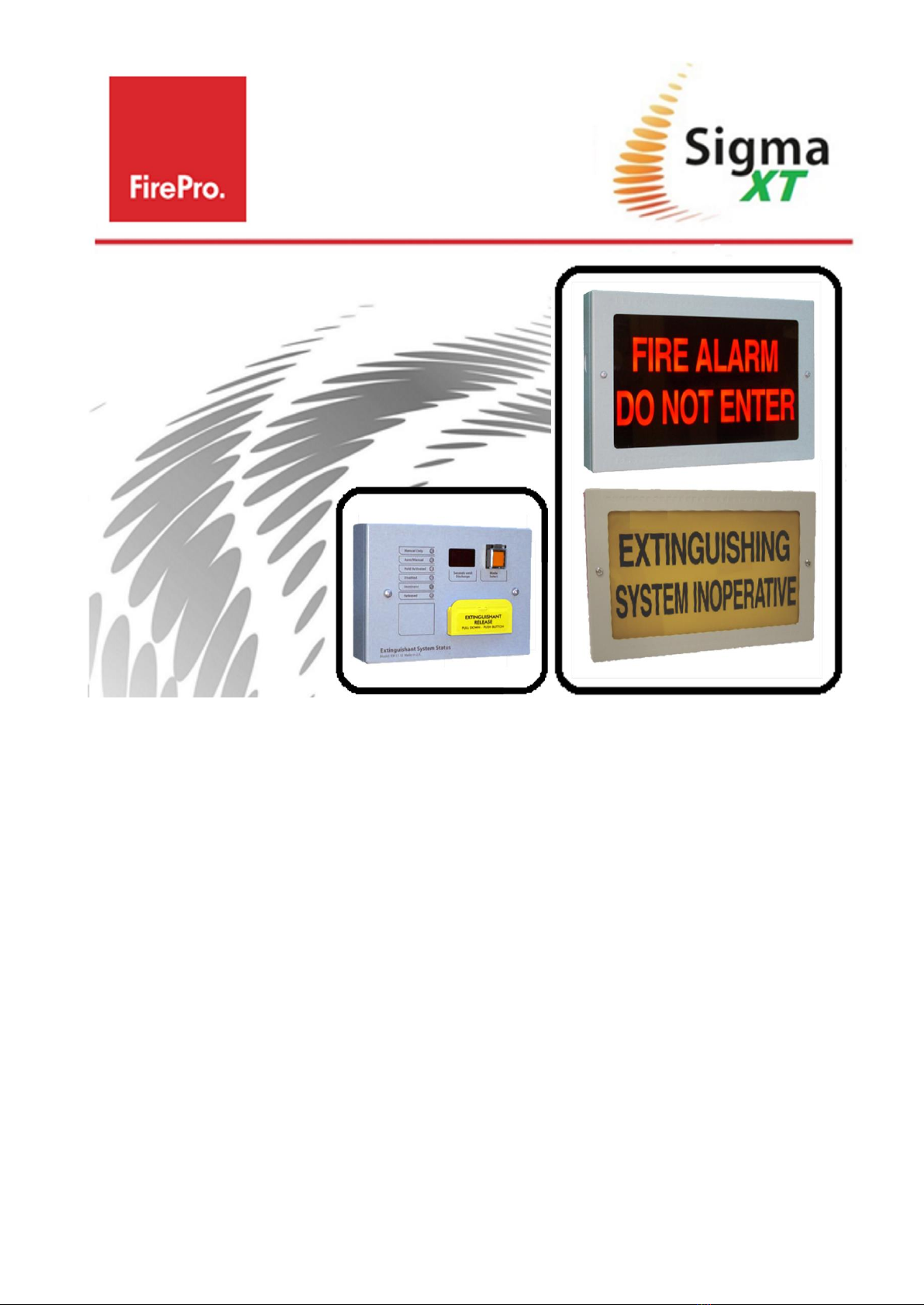
Fire Alarm and System Warning Signs
&
Local Control Stations
Installation and Operations Manual
Serial Communications Type
SIGMA-XT-FP Issue 3.5 March 2020

Sigma_XT_signs_m3.5.docx Page 2 of 14
Contents
1. Introduction............................................................................................................................................ 3
Sign Locations........................................................................................................................ 3
Local Control Stations (LCS) .................................................................................................... 3
External Devices..................................................................................................................... 3
Cable Penetrations and Terminations ....................................................................................... 3
2. Mounting................................................................................................................................................ 4
Internal Signs......................................................................................................................... 4
External Signs ........................................................................................................................ 4
3. Power and Data Connections ................................................................................................................... 5
Connecting Signs with RS485 Serial ......................................................................................... 5
3.1.1. Connecting up to 3 Signs .......................................................................................... 5
3.1.2. Connecting more than 3 Signs .................................................................................. 6
4. Connection of Local Control Station (LCS)................................................................................................. 7
Power and Data Connection .................................................................................................... 7
Connection to Hold and Mode inputs ....................................................................................... 8
Mode input............................................................................................................................. 8
Hold input.............................................................................................................................. 8
Mode select keyswitch ............................................................................................................ 8
Manual release ....................................................................................................................... 8
Processor and Watchdog Reset Switches ................................................................................. 9
Internal fault indications ......................................................................................................... 9
4.8.1. COM ........................................................................................................................ 9
4.8.2. LOCK OFF ................................................................................................................ 9
4.8.3. MOD........................................................................................................................ 9
4.8.4. FUSE ....................................................................................................................... 9
5. Setting up the Devices .......................................................................................................................... 10
Addressing Devices............................................................................................................... 10
Assigning Sign Function ........................................................................................................ 10
6. Adding Devices to FIP Programming....................................................................................................... 11
Adding / Removing Devices at the FIP ................................................................................... 11
7. Alternative Sign Arrangements............................................................................................................... 12
Mimic Signs / Connecting more than 7 Signs .......................................................................... 12
Alternative Arrangement of STATUS SERIAL (RS485) Circuit. .................................................. 13
8. Troubleshooting.................................................................................................................................... 14
9. Specifications........................................................................................................................................ 14
Sigma_XT_signs_m3.5.docx Page 3 of 14
1. Introduction
SIGNS - The illuminated warning
s
i
gn
s
p
r
ov
i
d
e
a c
l
ea
r
,
v
i
s
u
a
l
and
a
ud
i
b
l
e
w
a
r
n
i
ng
for a
f
i
r
e
alarm
,
e
x
t
i
n
guishant release
,
and System inoperative
.S
i
gn
s
have two levels of operation in which the top and bottom
halves of the
s
i
gn
may be split to
show an
i
n
i
t
i
a
l
w
a
r
n
i
ng
and then
a
dd
i
t
i
on
a
l
text for a
r
e
i
n
for
c
e
d
w
a
r
n
i
ng
,
or
both
h
a
l
v
e
s
can be activated at
on
c
e
.
LOCAL CONTROL STATION (LCS) may be required by standards for an installation. These units can be installed
using the serial bus and can be inserted anywhere in the 485 circuit.
A maximum of 7 devices (signs/LCS) can be installed when utilising the 485 Circuit.
Sign Locations
Locations where signs must be installed are defined by AS 1670. This manual does not replace reading the full
standard. Signs should be firmly mounted in appropriate locations. Interior signs are rated IP30 and are designed
for indoor use only. Weatherproof Signs are available. Signs are considered by the Sigma XT FIP to be OUTPUT
UNIT(S)
“FIRE ALARM/DO NOT ENTER” SIGNS - Installed outside the risk area, adjacent to all egress points and clearly
visible to anyone who may enter the risk area.
“FIRE ALARM/EVACUATE AREA” SIGNS - Installed inside the risk area, adjacent to all egress points and clearly
visible to all occupants of the risk area.
“EXTINGUISHING SYSTEM INOPERATIVE” SIGNS - Installed adjacent to the FIP and egress points, with additional
signs where necessary to be clearly visible to anyone who enters the risk area.
Local Control Stations (LCS)
LCS should be mounted firmly in an accessible location. The LCS is considered by the Sigma XT FIP to be a STATUS
UNIT(S). Status units have
monitored
inputs to which
remote
Hold or Mode select switches can be
co
nnected.
These
i
nputs
are monitored
for open and short circuit faults and
therefore
need to have a 470R 1W
trigge
r
resistor
connected
i
n
series with the
activating,
normally open switches and 6K8 0.5W end of
li
ne
monito
ring
resistors connected
across the end of the
cables
.
Status Units are environmental class A and are designed for indoor use only at temperatures between -50C (+/- 3)
and +400C (+/- 2) and with a maximum relative humidity of 95%. The IP rating for the enclosure is IP30. Operation
outside of these limits may render the equipment unsafe.
The 6K8 end-of-line monitoring
resistors
are supplied fitted to the Hold and Mode input terminals
External Devices
In addition to standard installation rules, there are some additional precautions that must be observed when
installing external signs.
SUNLIGHT - If an external sign is mounted in direct sunlight, it may be difficult to see if the sign is illuminated. In
this case it may be necessary to install a sun shield to make the illuminated sign visible.
DRIP LOOP - All external devices should be installed with cable penetrations coming through the bottom of the
sign, with a drip loop included to avoid the accumulation and ingress of water that may damage the electronics.
Cable Penetrations and Terminations
All cable penetrations into the sign enclosures must be protected by cable glands or bushings. Each sign enclosure
features a series of 20mm knockouts to accommodate these cable glands. The
m
a
x
s
i
z
e
of c
a
b
l
e
that the
t
e
rm
i
n
a
l
s
will
accommodate
i
s
2.5mm
.
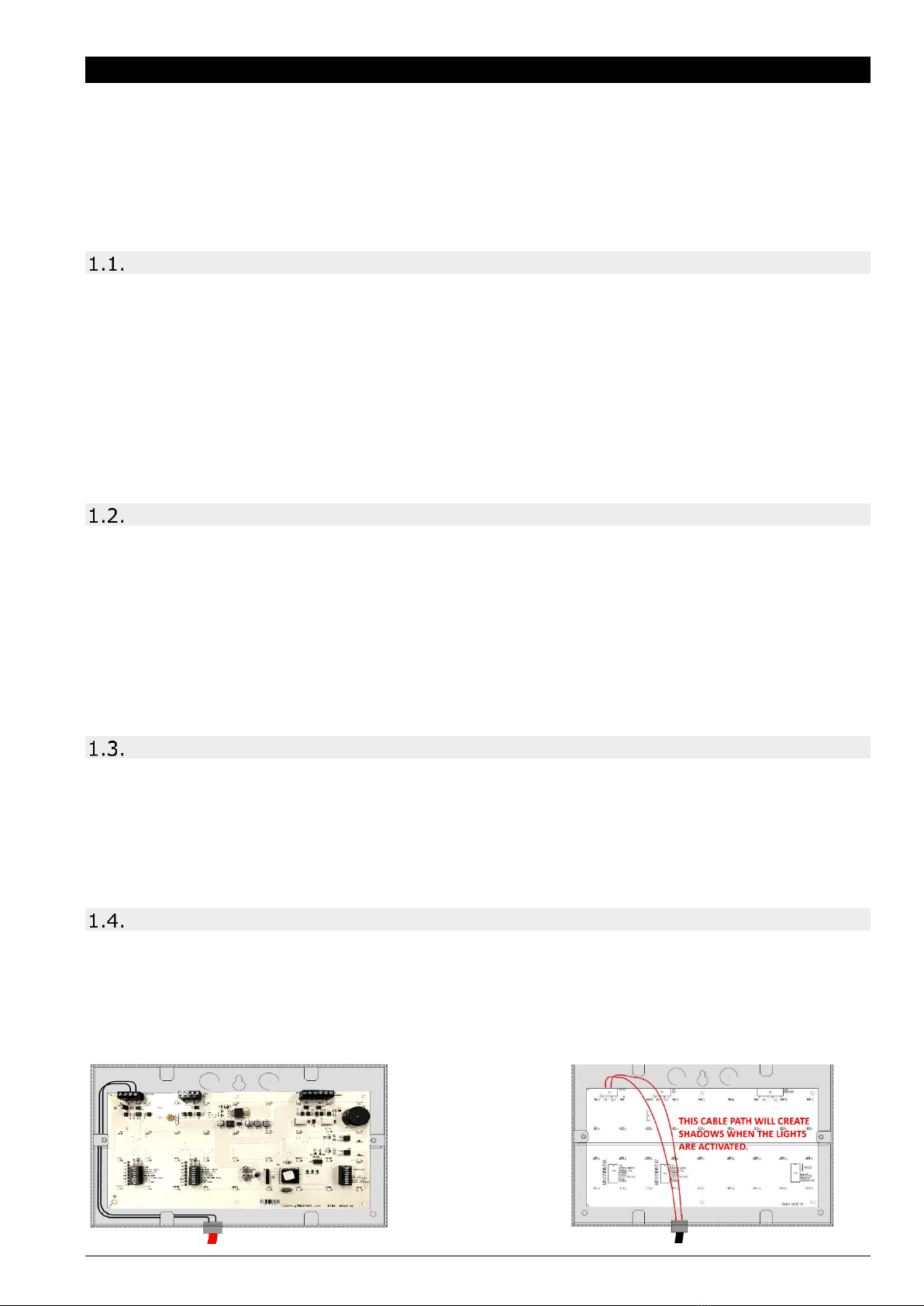
When preparing cable terminations, ensure that cables are not going to cross the front surface of the circuit board
as this will impair the light output of the unit, and the shadows generated by the cables will be clearly visible when
the sign is lit.

Sigma_XT_signs_m3.5.docx Page 4 of 14
2. Mounting
Internal Signs
Remove Cover and
Internal circuit board.
Mount using suitable
fixings.
Select cable entry point
and prepare.
Leave enough tail on
cable to ensure the
cable will not interfere
with operation of sign.
Weatherproof - External Signs
Mount Sunshade.
Remove cover and Internal
circuit board
Mount using suitable fixings
ONLY Mount to sunshade
surface –if the enclosure is
twisted on mounting it will crack
over time.
Best practice is to use silicon for
securing the lower half of sign.
Select cable entry point and
prepare. Cable entry must have
cable gland fitted. Preferred
entry though base of sign with
drip loop in cable.
Leave enough tail on cable to
ensure the cable will not
interfere with operation of sign.

Sigma_XT_signs_m3.5.docx Page 5 of 14
3. Power and Data Connections
Each status unit requires two cores for power and two cores for data transmission to and from the control panel.
A four core cable may be used for these connections. All of these connections are polarity conscious and care
should be taken to match the polarity with the corresponding terminals at the control panel.
Connecting Signs with RS485 Serial
3.1.1. Connecting up to 3 Signs
For systems requiring up to 3 signs (or devices) to be installed, wiring is as follows:
Notes:
•FIP MUST BE POWERED DOWN BEFORE ANY CHANGES TO SIGNS.
•STATUS POWER - will support a maximum of 3 devices, including both signs and LCS.
•For more than 3 signs, a separate power supply is required from the 24VDC output on the FIP.
•STATUS SERIAL (RS485) - Maximum number of devices, including both Signs and LCS, for the 485
communications is 7.

Sigma_XT_signs_m3.5.docx Page 6 of 14
3.1.2. Connecting more than 3 Signs
For systems requiring more than 3 signs (or devices), wiring is as follows:
Notes:
•FIP MUST BE POWERED DOWN BEFORE ANY CHANGES TO SIGNS.
•Connections for the first 3 signs or devices remains the same as the previous wiring diagram.
•For more than 3 signs, a separate power supply is required from the 24VDC output on the FIP.
•STATUS SERIAL (RS485) - Maximum number of devices, including both Signs and LCS, for the 485
communications is 7. RS485 connection remains the same for all 7 devices.

Sigma_XT_signs_m3.5.docx Page 7 of 14
4. Connection of Local Control Station (LCS)
Power and Data Connection
The LCS can be installed in any order on the STATUS SERIAL (RS485) circuit, depending on its location. The LCS
must be installed on the STATUS SERIAL (RS485) circuit. It cannot be used as a mimic device. More information
is available on the Local Control Station Manual.
For systems requiring a LCS to be installed, wiring is as follows:
Notes:
•FIP MUST BE POWERED DOWN BEFORE ANY CHANGES TO SIGNS.
•If installed as one of the first 3 devices on the STATUS SERIAL (RS485) circuit, STATUS POWER
may used for the power supply. STATUS POWER will support a maximum of 3 devices, including
both signs and LCS.
•If installed after the first 3 devices on the STATUS SERIAL (RS485) circuit, a separate power
supply is required from the 24VDC output on the FIP.
•STATUS SERIAL (RS485) - Maximum number of devices, including both Signs and LCS, for the 485
communications is 7.
Sigma_XT_signs_m3.5.docx Page 8 of 14
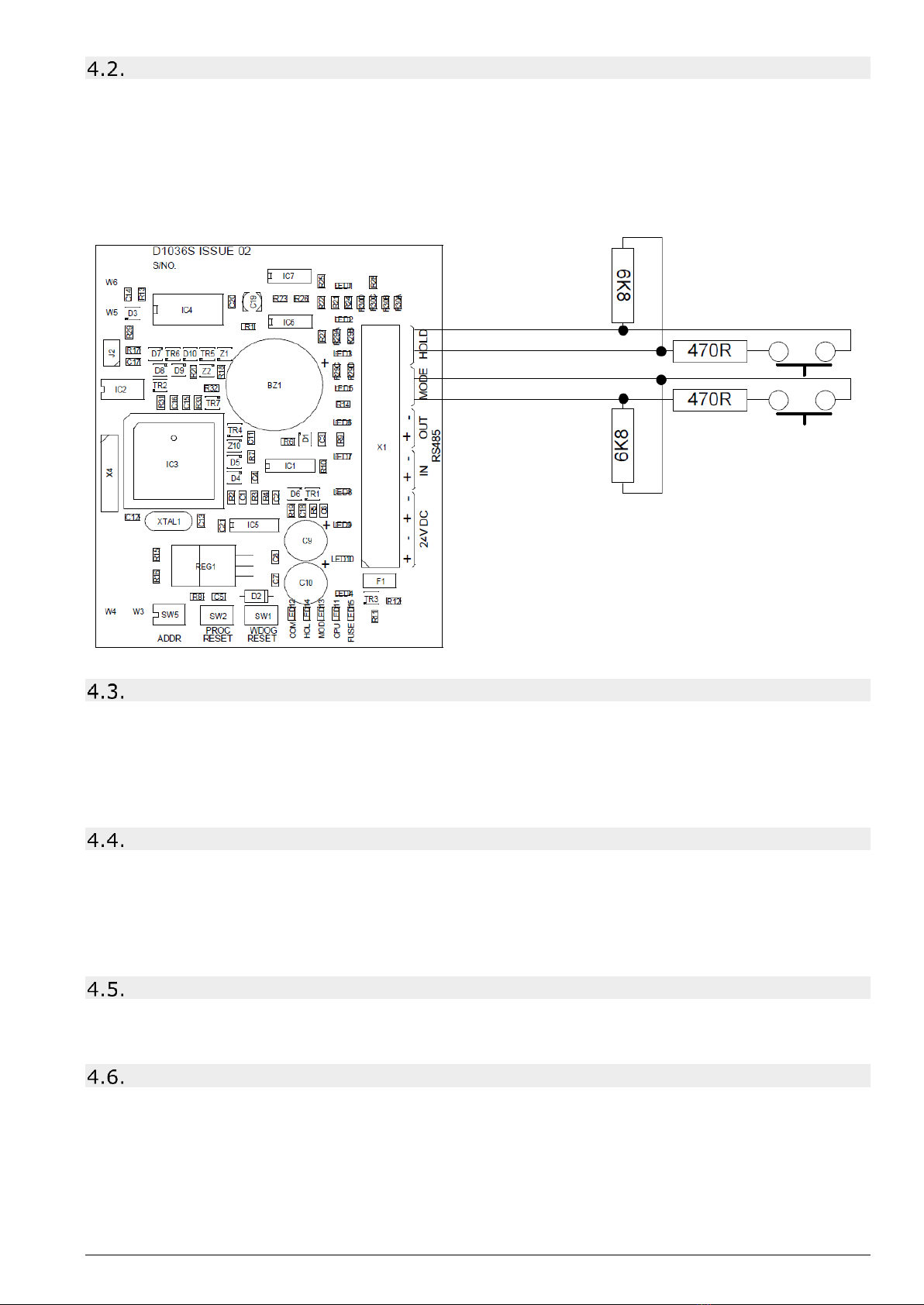
Connection to Hold and Mode inputs
Status units have monitored inputs to which remote Hold or Mode select switches can be connected. These inputs
are monitored for open and short circuit faults and therefore need to have a 470R 1W trigger resistor connected in
series with the activating, normally open switches and 6K8 0.5W end of line monitoring resistors connected across
the end of the cables.
The 6K8 end-of-line monitoring resistors are supplied fitted to the Hold and Mode input terminals and the 470R
trigger resistors are supplied in the accessory bag with the status unit. If either of these inputs are not being used
then the end of line monitoring resistors should be left in the Hold and/or Mode terminals.
Mode input
The mode input is provided to allow connection of remote mode switch or to connect to door interlock contacts.
The system is designed such that any Manual only mode input on the system that is active (input operated by 470R
trigger resistor) will put the system into Manual only mode regardless of the status of any other Mode inputs.
Therefore, for the system to be in Automatic and manual mode, all Mode inputs must be inactive.
Indication of the Mode is given on the front of the status unit by the Manual only or Automatic and manual LEDs.
Hold input
When active (input operated by a 470R trigger resistor) the Hold input allows the extinguishant release countdown
timer to be reset to its maximum time. When the input is de-activated the countdown to extinguishant release will
re-start at the maximum time that is configured at the panel (0 to 60 seconds).
IMPORTANT NOTE: When there is a fault on the HOLD input then the HOLD function is invoked which
means that the extinguishant release will not operate until this condition is cleared.
Mode select keyswitch
Some models of the status units have a mode select switch. The operation of the Mode select switch is as per the
Mode input above.
Manual release
Where fitted, a manual release button replicates the action of the manual release control at the main control panel
and once activated will start the extinguishant release sequence.
A plastic seal is provided in the accessory pack and should be fitted to the manual release flap with a piece of thin
wire to provide an indication if the manual release has been tampered with.
3 Processor and watchdog reset switches

Sigma_XT_signs_m3.5.docx Page 9 of 14
Processor and Watchdog Reset Switches
The status unit is controlled by a microprocessor, which will re-start
itself and continue to run if it stops for any reason such as severe
electrical interference such as an electrical storm.
To ensure that the unit is not being subjected to continual, undue
interference which may affect its proper operation, a CPU fault
indicator is latched on and a fault condition signalled to the control
panel.
If a processor re-start has occurred this latched fault condition will
need to be reset by pressing the WDOG RESET button on the bottom
of the PCB.
A switch is also provided to manually re-start the processor PROC
RESET. This switch can be used while the status units are connected
to the system to ensure that the unit starts up and establishes
communication with the panel in a controlled and expected manner.
Internal fault indications
An extinguishant fault indication at the control panel may mean that there are faults at one or more status
units. The status unit fault indications are located along the bottom of the PCB and are as follows:
4.8.1. COM
This LED indicates that the data communications connection to the control panel is not present. This may be
because the data lines are connected with reverse polarity or are not connected. Check RS485 IN and OUT
connections.
4.8.2. LOCK OFF
This LED indicates that the Lock Off input is open or short circuit. Check that the correct end of line resistor is
connected to the Lock Off terminals or at the end of the wires connected to the Lock Off terminals and that the
Lock Off input is not short circuited, or the wiring open circuited.
IMPORTANT NOTE: When there is a fault on the Lock Off input then the Lock Off function is invoked which means that the
extinguishant release will not operate until this condition is cleared.
4.8.3. MOD
This LED indicates that the MODE input is open or short circuit. Check that the correct end of line resistor is
connected to the MODE terminals or at the end of the wires connected to the MODE input and that the MODE input
is not short circuited.
4.8.4. FUSE
This LED indicates that the electronic fuse has operated. Under this condition, the status unit is not operational.
This may be due to incorrect polarity of the power connection or a failure on the unit itself.

Sigma_XT_signs_m3.5.docx Page 10 of 14
5. Setting up the Devices
Sign Circuit Board
LCS Circuit Board
Addressing Devices
Before adding a device to the FIP’s programming, each device connected to the STATUS SERIAL (RS485) circuit
must be given an individual address. The FIP MUST BE POWERED DOWN BEFORE ANY CHANGES TO DEVICES.
IMPORTANT - Devices with the same address will cause an intermittent fault to be displayed.
Assigning Sign Function
In addition to addressing, signs connected to the STATUS SERIAL (RS485) circuit require their function to be set
using the DIL switches on the bottom of the sign circuit board. The functions of the upper and lower halves of the
sign are split across 3 banks of DIL switches. The recommended sign functions for each type of sign are:
Sigma_XT_signs_m3.5.docx Page 11 of 14
6. Adding Devices to FIP Programming
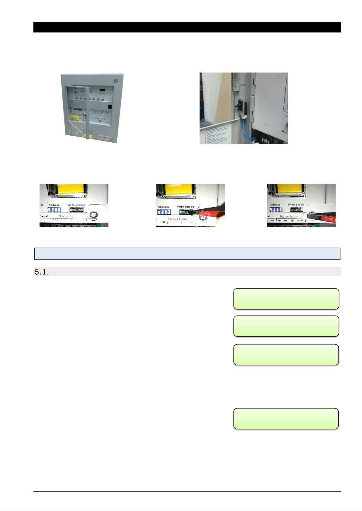
In order to add or remove devices from the FIP programming, the FIP must be in “ACCESS LEVEL 3”.
The steps to enter “ACCESS LEVEL 3” are as follows:
1. Unlock and open the centre display window. This operates a read switch on the door that enables “ACCESS
LEVEL 2”. The centre lock opens the display window, allowing for operation of the controls.
2. Unlock and open the main door for the FIP. The top and bottom locks will open the complete cabinet front
allowing for full access to the FIP controls. Ensure that the display window is kept open.
3. Move the Write/Enable switch on the lower extinguishant module to the left “Write” position. This enable
“ACCESS LEVEL 3” and allows for programming of the signs.
A “CONFIG WP” Fault will show if the Slide Switch is not returned “ENABLE”.
Adding / Removing Devices at the FIP
FIP SHOULD BE POWERED DOWN before any changes are made to status units. When the system is first powered
on, it will search for connected status units connected to extinguishant
module. If status units are connected correctly and detected by the
control FIP, the LCD will display:
Open the
Display
Window and Press
Enter
on the module to which the
status units are connected. Use the “+” button on the module to view
the faults. If status units are detected the LCD will display, X = the
address of the status unit found.
To accept the status units found, slide the WRITE ENABLE switch,
on the module to which the status units or ancillary boards are
connected to write mode. The LCD will then display, X= the address of
the status unit found.
Then press the
Enter
button, the selected status unit or ancillary board will be added to the system and the next
unit to be added will be displayed. Press the
Enter
button on the extinguishant module until all the units have been
accepted then slide the
Write Enable
switch to enable mode.
All of the status units found module have now been added and disconnection of any of them will be displayed as a
fault on the module and on the detection part of the system. If any
status units are disconnected, a Lock Off activated indication will also
be displayed at the extinguishant module and all ancillary boards or
status units that remain connected. With the
Display Window
Closed,
the LCD will display:
The Status units which are disconnected will have all their indicators flashing. When additional status units are
added, these will be shown on the LCD when the system is powered up.
Normal –The Slide
Switch is to the Right
To Access Level 3 –move the
Slide Switch to the Left
Access Level 3 –The Slide
Switch is to the Left
REMOTE BUS
FAULT
X FAULTS
Enter TO VIEW
STATUS UNIT X
FAULT
STATUS UNIT X
Enter TO ACCEPT

Sigma_XT_signs_m3.5.docx Page 12 of 14
7. Alternative Sign Arrangements
Mimic Signs / Connecting more than 7 Signs
In systems that require more than 7 signs, additional signs may be installed by connecting to the 24VDC TRIGGER
terminals located in each sign. This allows connected signs to mimic the operation of a sign that is connected to
the STATUS SERIAL (RS485) circuit. Note: signs can only mimic other signs of the same type (A “Do Not Enter”
Sign can only mimic another “Do Not Enter” Sign).
The 24VDC trigger function of each sign connected to the STATUS SERIAL (RS485) circuit can support up to 3
additional signs.
There is no need to configure the address or sign function switches, however the internal buzzer and flashing
functions can still be adjusted separately.
IMPORTANT –An additional external power supply OR an upgraded power supply in the FIP is required for any
additional devices over the standard maximum of 7 devices. Each sign has a current draw of 140mA. When installing,
power supply (including backup supply) must be assessed to ensure that it will be adequate.
While it is possible to use this configuration with fewer than 7 devices, it is not recommended.
The LCS must be installed on the STATUS SERIAL (RS485) circuit. It cannot be used as a mimic device.
24VDC Trigger Terminals
+
Power Supply
1
Controls LOWER half of mimic sign
2
Controls UPPER half of mimic sign
Sigma_XT_signs_m3.5.docx Page 13 of 14
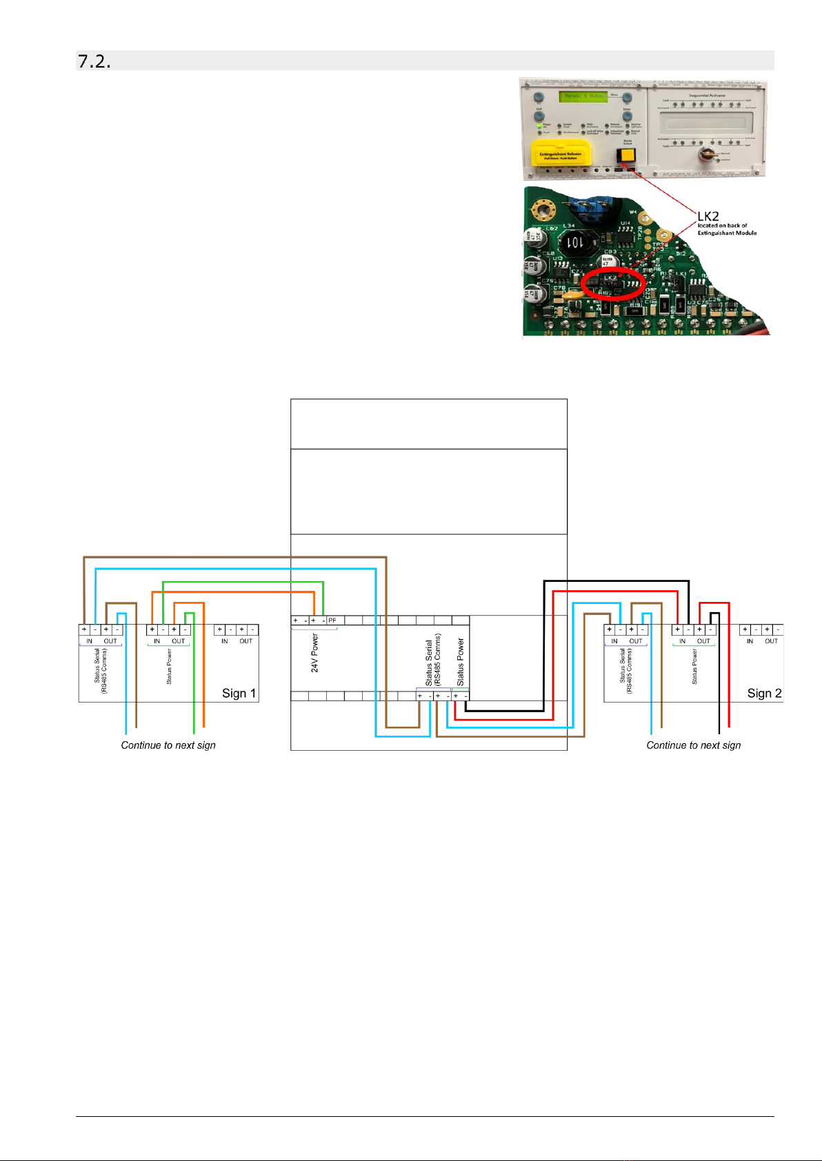
Alternative Arrangement of STATUS SERIAL (RS485) Circuit.
The standard arrangement for installing signs is to have a single
STATUS SERIAL (RS485) cable connecting the FIP to the signs, as per
wiring diagram. However, it can be configured to have 2 separate
cables for the RS485 circuit with the FIP effectively in the middle of
the circuit rather than at one end.
FIP MUST BE POWERED DOWN BEFORE ANY CHANGES TO SIGNS. If
process is done with power connected the is a possibility that a short
could occur and damage the FIP.
IMPORTANT - When this configuration is used the LK2 link on the
extinguishant module MUST be removed or positioned over 1 pin only,
or the FIP will register a fault.
An example of this type of wiring arrangement is as follows:

Sigma_XT_signs_m3.5.docx Page 14 of 14
8. Troubleshooting
Output Unit refers to a SIGN, this fault will be
•Address is the same as another device in the 485 circuit
•Power has failed to the sign.
•RS485 signal has failed to the sign.
Status Unit refers to an LCS, this fault will be
•Address is the same as another device in the 485 circuit
•Power has failed to the LCS.
•RS485 signal has failed to the LCS.
9. Specifications
Internal Sign
External Sign
Local Control Station
Size
195 x 300 x 50mm
195 x 300 x 50mm
135 x 186 x 50mm
Material
1.2mm
s
t
ee
l
Epoxy coat
Thermoplastic
1.2mm steel Epoxy coat
IP Rating
IP 40
IP 55
IP 40
Op. Voltage
15V to 30V DC
15V to 30V DC
21 to 30v DC
Current –Quiesant
20 mA
20 mA
60 mA
Current –Alarm State
140 mA
140 mA
70 mA
OUTPUT UNIT X →
FAULT
STATUS UNIT X →
FAULT
Other manuals for Sigma XT
1
Table of contents
Other Fire Pro Fire Alarm manuals

Popular Fire Alarm manuals by other brands

Wheelock
Wheelock Series RSS specification

Global Fire
Global Fire ORION 4 Installation, operation and maintenance manual

Bosch
Bosch FSM-2000 installation guide

olympia electronics
olympia electronics BSR-1000 manual

Honeywell
Honeywell Notifier ID60 operating manual

Simplex
Simplex 4606-9102 installation instructions

Greenheck
Greenheck Combination Fire Smoke Dampers FSD-M211 Specifications

ESP
ESP BS5839 Guide
Brooks
Brooks FIRETRACKER FT128 Quick operation guide

Evacuator
Evacuator Synergy Zone Leader quick start guide

Cooper Notification
Cooper Notification ET70-24MCCH Series installation instructions

ADEMCO
ADEMCO 1022 Troubleshooting


